EP1302797A2 - Zentrales Festigkeitsglied mit reduzierter radialer Steifigkeit für optische Kabel - Google Patents
Zentrales Festigkeitsglied mit reduzierter radialer Steifigkeit für optische Kabel Download PDFInfo
- Publication number
- EP1302797A2 EP1302797A2 EP02022901A EP02022901A EP1302797A2 EP 1302797 A2 EP1302797 A2 EP 1302797A2 EP 02022901 A EP02022901 A EP 02022901A EP 02022901 A EP02022901 A EP 02022901A EP 1302797 A2 EP1302797 A2 EP 1302797A2
- Authority
- EP
- European Patent Office
- Prior art keywords
- strength
- optical fiber
- tube
- fiber cable
- cable configuration
- Prior art date
- Legal status (The legal status is an assumption and is not a legal conclusion. Google has not performed a legal analysis and makes no representation as to the accuracy of the status listed.)
- Withdrawn
Links
- 230000003287 optical effect Effects 0.000 title description 5
- 239000013307 optical fiber Substances 0.000 claims abstract description 79
- XLYOFNOQVPJJNP-UHFFFAOYSA-N water Substances O XLYOFNOQVPJJNP-UHFFFAOYSA-N 0.000 claims abstract description 17
- 230000004888 barrier function Effects 0.000 claims abstract description 10
- 239000000463 material Substances 0.000 claims description 23
- 239000011152 fibreglass Substances 0.000 claims description 9
- 239000004033 plastic Substances 0.000 claims description 7
- 229920003023 plastic Polymers 0.000 claims description 7
- 238000005728 strengthening Methods 0.000 claims description 7
- 239000000843 powder Substances 0.000 abstract description 7
- 230000035515 penetration Effects 0.000 abstract description 4
- 230000006835 compression Effects 0.000 description 10
- 238000007906 compression Methods 0.000 description 10
- 239000000835 fiber Substances 0.000 description 9
- 238000005452 bending Methods 0.000 description 6
- 239000011521 glass Substances 0.000 description 5
- -1 polypropylene Polymers 0.000 description 5
- 230000008602 contraction Effects 0.000 description 4
- 230000008859 change Effects 0.000 description 3
- 238000005253 cladding Methods 0.000 description 3
- 230000000694 effects Effects 0.000 description 3
- 238000009434 installation Methods 0.000 description 3
- 229920001707 polybutylene terephthalate Polymers 0.000 description 3
- 239000004743 Polypropylene Substances 0.000 description 2
- VYPSYNLAJGMNEJ-UHFFFAOYSA-N Silicium dioxide Chemical compound O=[Si]=O VYPSYNLAJGMNEJ-UHFFFAOYSA-N 0.000 description 2
- 239000002131 composite material Substances 0.000 description 2
- 230000008878 coupling Effects 0.000 description 2
- 238000010168 coupling process Methods 0.000 description 2
- 238000005859 coupling reaction Methods 0.000 description 2
- 239000002184 metal Substances 0.000 description 2
- 229910052751 metal Inorganic materials 0.000 description 2
- 230000005012 migration Effects 0.000 description 2
- 238000013508 migration Methods 0.000 description 2
- 229910052755 nonmetal Inorganic materials 0.000 description 2
- 229920001155 polypropylene Polymers 0.000 description 2
- 230000001681 protective effect Effects 0.000 description 2
- 230000000930 thermomechanical effect Effects 0.000 description 2
- 239000004698 Polyethylene Substances 0.000 description 1
- 229910000831 Steel Inorganic materials 0.000 description 1
- 230000015572 biosynthetic process Effects 0.000 description 1
- 229910052681 coesite Inorganic materials 0.000 description 1
- 229910052906 cristobalite Inorganic materials 0.000 description 1
- 230000006378 damage Effects 0.000 description 1
- 230000003247 decreasing effect Effects 0.000 description 1
- 238000011161 development Methods 0.000 description 1
- 238000005755 formation reaction Methods 0.000 description 1
- 238000010438 heat treatment Methods 0.000 description 1
- 238000004519 manufacturing process Methods 0.000 description 1
- 239000002905 metal composite material Substances 0.000 description 1
- 229910001092 metal group alloy Inorganic materials 0.000 description 1
- 230000004048 modification Effects 0.000 description 1
- 238000012986 modification Methods 0.000 description 1
- 229920000573 polyethylene Polymers 0.000 description 1
- 229920000915 polyvinyl chloride Polymers 0.000 description 1
- 230000009528 severe injury Effects 0.000 description 1
- 230000008054 signal transmission Effects 0.000 description 1
- 239000000377 silicon dioxide Substances 0.000 description 1
- 239000007787 solid Substances 0.000 description 1
- 239000010959 steel Substances 0.000 description 1
- 229910052682 stishovite Inorganic materials 0.000 description 1
- 238000006467 substitution reaction Methods 0.000 description 1
- 238000012360 testing method Methods 0.000 description 1
- 229910052905 tridymite Inorganic materials 0.000 description 1
Images


Classifications
-
- G—PHYSICS
- G02—OPTICS
- G02B—OPTICAL ELEMENTS, SYSTEMS OR APPARATUS
- G02B6/00—Light guides; Structural details of arrangements comprising light guides and other optical elements, e.g. couplings
- G02B6/44—Mechanical structures for providing tensile strength and external protection for fibres, e.g. optical transmission cables
- G02B6/4401—Optical cables
- G02B6/4429—Means specially adapted for strengthening or protecting the cables
- G02B6/4434—Central member to take up tensile loads
-
- G—PHYSICS
- G02—OPTICS
- G02B—OPTICAL ELEMENTS, SYSTEMS OR APPARATUS
- G02B6/00—Light guides; Structural details of arrangements comprising light guides and other optical elements, e.g. couplings
- G02B6/44—Mechanical structures for providing tensile strength and external protection for fibres, e.g. optical transmission cables
- G02B6/4401—Optical cables
- G02B6/441—Optical cables built up from sub-bundles
- G02B6/4411—Matrix structure
-
- G—PHYSICS
- G02—OPTICS
- G02B—OPTICAL ELEMENTS, SYSTEMS OR APPARATUS
- G02B6/00—Light guides; Structural details of arrangements comprising light guides and other optical elements, e.g. couplings
- G02B6/44—Mechanical structures for providing tensile strength and external protection for fibres, e.g. optical transmission cables
- G02B6/4401—Optical cables
- G02B6/4429—Means specially adapted for strengthening or protecting the cables
- G02B6/44384—Means specially adapted for strengthening or protecting the cables the means comprising water blocking or hydrophobic materials
Definitions
- a traditional optical fiber cable configuration 10 is shown in Figure 1.
- An outer jacket 12 is provided to enclose and protect a plurality of buffer tubes 14.
- the buffer tubes may contain loose optical fibers, or optical fiber ribbons 16.
- the buffer tubes 14 are radially disposed around a central strength member (CSM) 18.
- the CSM is commonly made of glass reinforced plastic (GRP) and is used to provide strength and support to the cable configuration 10.
- GRP glass reinforced plastic
- Each of the buffer tubes 14 may contain loose fibers 16 or fiber ribbons.
- U.S. Pat. No. 5,621,841 discloses an optical fiber configuration having a CSM.
- the buffer tubes are stranded or wrapped around the CSM.
- the buffer tubes are enclosed by an armor layer and an outer sheath.
- a tube 30 with a bending stiffness close to that of the buffer tubes 24 it is desired to have a tube 30 with a bending stiffness close to that of the buffer tubes 24.
- the bending stiffness of a traditional CSM is typically much greater than the bending stiffness of surrounding buffer tubes.
- An inner strength member or strength rod 32 is disposed longitudinally within the hollow portion of the tube 30, and may comprise a high-strength, high-Young's modulus material such as a glass-reinforced plastic. Also, a varying number of strength rods 32 may be used in the tube 30 depending on the application. To avoid water penetration or a "water hose" effect, the tube is filled with a gel or water-absorbing powder 29 or any other water barrier material known in the art.
- An inner diameter of the hollow tube 30 is dimensioned to be larger that an outside diameter of the strength rod 32, such that an open space exists between at least a portion of the strength rod 32 and an inner wall 33 of the tube 30. Because of the space between the strength rod 32 and the tube 30, the strength rod 32 is permitted to move around in the hollow portion of the tube 30.
- Other high-strength, high-Young's modulus materials such as steel wire and other metal alloys, and metal and non-metal composites with a low coefficient of thermal expansion, can be used as the strength rod 32.
- the use of a material having a low coefficient of thermal expansion is preferred due to its resistance to thermal contraction at low temperatures.
- a tubular outer jacket 22 is used to house a plurality of buffer tubes 24, which are preferably disposed in a radial arrangement, and contain an arrangement of optical fibers, such as in the form of ribbons 26.
- Figure 6 shows the optical fiber configuration 20 of Figure 5 being acted on by an external compression force F, such as that caused by a sheave load.
- F an external compression force
- a sheave load is caused by the cable 20 being dragged over a sheave.
- the strength rods 38 will provide support for the CSM 34 during deflection caused by the load. For example, three parallel rods positioned approximately 120° with respect to each other will not engage with each other, thus allowing for a larger deformation of the tube 36 without increased resistance.
- the load between the sheave and strength rods 38 is a function of speed, wherein the movability of the strength rods 38 allows for the load to be distributed in accordance with the load. After the load is removed, the strength rods 38 are operable to return back to their initial position.
- the cross-sectional area of the single strength rod 32 of Figures 3 and 4 be equal to the sum of the cross-sectional areas of the plurality of strength rods 38 of Figures 5 and 6, if they are made of the same material.
- other relative dimensions are considered to be within the scope of the invention.
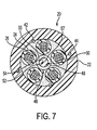
- Figure 7 illustrates an even further embodiment of an optical fiber cable configuration 20 according to the present invention. Similar to the previous embodiments, a tubular outer jacket 22 is used to house a plurality of buffer tubes 24, which are preferably disposed in a radial arrangement, and contain an arrangement of optical fibers, such as in the form of ribbons 26.
- a tubular outer jacket 22 is used to house a plurality of buffer tubes 24, which are preferably disposed in a radial arrangement, and contain an arrangement of optical fibers, such as in the form of ribbons 26.
- the strength rods 52 may respectively be made of a material such as a glass reinforced plastic, as is also described above in reference to the embodiment of Figure 3.
- the strength tube 48 may be filled with a gel or water-absorbing powder 57 or any other water barrier material known in the art.
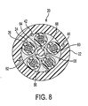
- a CSM 56 is preferably positioned centrally with respect to the outer jacket 22.
- the CSM 56 also includes a strength tube 58 made of, for example, a plastic, and has a center portion 60.
- a plurality of inner strength members or strength rods 62 are entirely disposed, in a longitudinal direction, within a wall 64 of the strength tube 58.
- the strength rods 62 may respectively be made of a material, such as a glass reinforced plastic, as is similarly described above in other embodiments.
- the strength tube 58 may be filled with a gel or water-absorbing powder 66 or any other water barrier material known in the art.
- This embodiment differs from that of Figure 7 in that the strength rods 62 are completely embedded within the wall 64 of the strength tube 58 and do not extend into the center portion 60. As shown in Figure 8, three strength rods 62 are disposed within the tube wall 64 to provide strength and resistance to thermal contraction. However, as one skilled in the art will appreciate, more or less strength rods 62 may be used depending on the particular application.
- strength yarn 42 and radial strength members 44 may be positioned in or under the outer jacket in a traditional way.
- the additional load-carrying strength yarns and radial strength members may be added if there is a need to increase the stiffness of the load-carrying elements.
Landscapes
- Physics & Mathematics (AREA)
- General Physics & Mathematics (AREA)
- Optics & Photonics (AREA)
- Laying Of Electric Cables Or Lines Outside (AREA)
- Electric Cable Installation (AREA)
- Insulated Conductors (AREA)
- Communication Cables (AREA)
Applications Claiming Priority (4)
| Application Number | Priority Date | Filing Date | Title |
|---|---|---|---|
| US972901 | 2001-10-10 | ||
| US09/972,901 US20030068145A1 (en) | 2001-10-10 | 2001-10-10 | Central strength member with reduced radial stiffness |
| US10/141,871 US6654525B2 (en) | 2001-10-10 | 2002-05-10 | Central strength member with reduced radial stiffness |
| US141871 | 2002-05-10 |
Publications (2)
| Publication Number | Publication Date |
|---|---|
| EP1302797A2 true EP1302797A2 (de) | 2003-04-16 |
| EP1302797A3 EP1302797A3 (de) | 2004-11-17 |
Family
ID=26839531
Family Applications (1)
| Application Number | Title | Priority Date | Filing Date |
|---|---|---|---|
| EP02022901A Withdrawn EP1302797A3 (de) | 2001-10-10 | 2002-10-10 | Zentrales Festigkeitsglied mit reduzierter radialer Steifigkeit für optische Kabel |
Country Status (2)
| Country | Link |
|---|---|
| US (1) | US6654525B2 (de) |
| EP (1) | EP1302797A3 (de) |
Cited By (2)
| Publication number | Priority date | Publication date | Assignee | Title |
|---|---|---|---|---|
| EP1881353A1 (de) * | 2006-07-19 | 2008-01-23 | Draka Comteq B.V. | Glasfaserkabel und Verfahren zu dessen Abänderung |
| WO2013165407A1 (en) | 2012-05-02 | 2013-11-07 | Cignarale Joseph | Round and small diameter optical cables with a ribbon-like optical fiber structure |
Families Citing this family (21)
| Publication number | Priority date | Publication date | Assignee | Title |
|---|---|---|---|---|
| US20090190890A1 (en) * | 2002-12-19 | 2009-07-30 | Freeland Riley S | Fiber optic cable having a dry insert and methods of making the same |
| FR2851686B1 (fr) * | 2003-02-25 | 2006-03-03 | Cit Alcatel | Isolateur electrique |
| US20060104580A1 (en) * | 2004-11-15 | 2006-05-18 | Samsung Electronics Co,; Ltd | Optical fiber cable |
| US7123801B2 (en) * | 2004-11-18 | 2006-10-17 | Prysmian Communications Cables And Systems Usa, Llc | Optical fiber cable with fiber receiving jacket ducts |
| US7289704B1 (en) * | 2006-10-31 | 2007-10-30 | Corning Cable Systems Llc | Fiber optic cables that kink with small bend radii |
| US7724998B2 (en) * | 2007-06-28 | 2010-05-25 | Draka Comteq B.V. | Coupling composition for optical fiber cables |
| US7639915B2 (en) * | 2007-06-28 | 2009-12-29 | Draka Comteq B.V. | Optical fiber cable having a deformable coupling element |
| US7646952B2 (en) | 2007-06-28 | 2010-01-12 | Draka Comteq B.V. | Optical fiber cable having raised coupling supports |
| NL2002891C2 (en) * | 2009-05-14 | 2010-11-18 | Draka Comteq Bv | Aerial signal conductor holder. |
| CN102782551B (zh) * | 2009-12-14 | 2016-05-11 | 康宁光缆系统有限责任公司 | 多光纤子单元电缆 |
| BR112012031113A2 (pt) | 2010-06-08 | 2016-11-01 | Dow Global Technologies Llc | cabo |
| IT1404661B1 (it) * | 2010-06-24 | 2013-11-29 | Brugg Ag Kabelwerke | Cavo composito atto a fungere da infrastruttura per telecomunicazioni per l'utilizzo in ambienti severi e non convenzionali. |
| CA2812746C (en) * | 2010-09-29 | 2017-08-29 | Dow Global Technologies Llc | Flexible strength members for wire cables |
| US8682124B2 (en) | 2011-10-13 | 2014-03-25 | Corning Cable Systems Llc | Access features of armored flat fiber optic cable |
| US9523832B2 (en) * | 2012-03-23 | 2016-12-20 | Afl Telecommunications Llc | High temperature, zero fiber strain, fiber optic cable |
| USD860264S1 (en) * | 2018-01-16 | 2019-09-17 | Mid-South Control Line, Llc | Encapsulated conduits having jacket with sections of reduced material |
| USD860263S1 (en) * | 2018-01-16 | 2019-09-17 | Mid-South Control Line, Llc | Encapsulated conduit having jacket with sections of reduced material |
| US10120152B1 (en) | 2018-02-13 | 2018-11-06 | Superior Essex International LP | All dielectric self-supporting fiber optic cable |
| US11262516B2 (en) | 2018-07-05 | 2022-03-01 | Prysmian S.P.A. | High density optical cables |
| US20200012059A1 (en) * | 2018-07-05 | 2020-01-09 | Prysmian S.P.A. | High Density Optical Cables |
| US12111506B1 (en) * | 2024-03-24 | 2024-10-08 | Samuel Messinger | Submarine oceanic fiber optic cable apparatus for increased data transmission and method of use |
Citations (1)
| Publication number | Priority date | Publication date | Assignee | Title |
|---|---|---|---|---|
| US5982965A (en) * | 1996-11-08 | 1999-11-09 | Sat Societe Anonyme De Telecommunications | Optical fiber telecommunications cable |
Family Cites Families (17)
| Publication number | Priority date | Publication date | Assignee | Title |
|---|---|---|---|---|
| GB2019601A (en) * | 1978-04-20 | 1979-10-31 | Telephone Cables Ltd | Optical fibre cables |
| US4515435A (en) | 1982-08-10 | 1985-05-07 | Cooper Industries, Inc. | Thermally stabilized fiber optic cable |
| DE3585259D1 (de) | 1984-09-21 | 1992-03-05 | Bicc Plc | Optisches kabel. |
| US5389442A (en) | 1988-07-11 | 1995-02-14 | At&T Corp. | Water blocking strength members |
| GB8902552D0 (en) * | 1989-02-06 | 1989-03-22 | Telephone Cables Ltd | Optical fibre cable core for submarine use |
| US5268983A (en) | 1992-12-08 | 1993-12-07 | Alcoa Fujikura Ltd. | Round, dry, all dielectric, fan out compact optical fiber cable |
| TW320726B (de) * | 1995-04-28 | 1997-11-21 | At & T Corp | |
| US5621841A (en) | 1995-09-20 | 1997-04-15 | Siecor Corporation | Optical fiber cable containing ribbons in stranded tubes |
| US5630003A (en) * | 1995-11-30 | 1997-05-13 | Lucent Technologies Inc. | Loose tube fiber optic cable |
| US5751879A (en) | 1995-12-28 | 1998-05-12 | Lucent Technologies Inc. | Wound optical fiber cable including robust component cable(s) and a system for manufacture of the cable |
| FR2760540B1 (fr) | 1997-03-10 | 1999-04-16 | Alsthom Cge Alcatel | Cable a fibres optiques serrees dans une gaine |
| DE19717313A1 (de) * | 1997-04-24 | 1998-11-05 | Alsthom Cge Alcatel | Optisches Kabel und Verfahren zum Herstellen eines optischen Kabels |
| DE29721701U1 (de) * | 1997-12-09 | 1998-05-07 | Deutsche Telekom AG, 53113 Bonn | Glasfaser- bzw. Lichtwellenkabel mit hohlen Stützelement/Röhrchen |
| US6377738B1 (en) * | 1998-12-04 | 2002-04-23 | Pirelli Cable Corporation | Optical fiber cable and core with a reinforced buffer tube having visible strength members and methods of manufacture thereof |
| US6278833B1 (en) * | 1999-08-18 | 2001-08-21 | Jean Hway Lee | Light-emitting device for emitting neon-like light |
| JP2001093210A (ja) * | 1999-09-20 | 2001-04-06 | Sony Corp | データ記録再生装置 |
| BR0113126A (pt) * | 2000-08-07 | 2003-07-29 | Pirelli General Plc | Cabo de fibra óptica possuindo um núcleo |
-
2002
- 2002-05-10 US US10/141,871 patent/US6654525B2/en not_active Expired - Fee Related
- 2002-10-10 EP EP02022901A patent/EP1302797A3/de not_active Withdrawn
Patent Citations (1)
| Publication number | Priority date | Publication date | Assignee | Title |
|---|---|---|---|---|
| US5982965A (en) * | 1996-11-08 | 1999-11-09 | Sat Societe Anonyme De Telecommunications | Optical fiber telecommunications cable |
Cited By (5)
| Publication number | Priority date | Publication date | Assignee | Title |
|---|---|---|---|---|
| EP1881353A1 (de) * | 2006-07-19 | 2008-01-23 | Draka Comteq B.V. | Glasfaserkabel und Verfahren zu dessen Abänderung |
| US7991256B2 (en) | 2006-07-19 | 2011-08-02 | Draka Comteq, B.V. | Optical fiber cable and method for modifying the same |
| WO2013165407A1 (en) | 2012-05-02 | 2013-11-07 | Cignarale Joseph | Round and small diameter optical cables with a ribbon-like optical fiber structure |
| US11592632B2 (en) | 2012-05-02 | 2023-02-28 | Afl Telecommunications Llc | Round and small diameter optical cables with a ribbon-like optical fiber structure |
| US12164165B2 (en) | 2012-05-02 | 2024-12-10 | Afl Telecommunications Llc | Round and small diameter optical cables with a ribbon-like optical fiber structure |
Also Published As
| Publication number | Publication date |
|---|---|
| US20030068146A1 (en) | 2003-04-10 |
| EP1302797A3 (de) | 2004-11-17 |
| US6654525B2 (en) | 2003-11-25 |
Similar Documents
| Publication | Publication Date | Title |
|---|---|---|
| US6654525B2 (en) | Central strength member with reduced radial stiffness | |
| JPS6030729Y2 (ja) | 光学通信ケ−ブル | |
| EP1489447B1 (de) | Faseroptisches Kabel welches keine Verstärkungselemente aufweist und einen reduzierten Wärmeausdehnungskoeffizienten hat | |
| EP1887396B1 (de) | Lichtwellenleiter-Telekommunikationskabel | |
| JP2523129B2 (ja) | 光ファイバケ−ブル | |
| JPH03209409A (ja) | 光ファイバケーブルコア | |
| JP2016532137A (ja) | 延伸適性のある光ファイバケーブル | |
| NZ270898A (en) | Optical fibre cable with reinforced buffer tube around fibres | |
| CA2005114C (en) | All-dielectric optical fiber cable having enhanced fiber access | |
| EP1359448B1 (de) | Optisches Flachbandkabel mit losen Hohladern | |
| US20030165310A1 (en) | Compact optical cable | |
| CN100462760C (zh) | 改良的光缆 | |
| EP1288690B1 (de) | Optisches Hohladerkabel mit Faserbändchen | |
| KR100575954B1 (ko) | 공기압 포설용 광케이블 | |
| US7421169B2 (en) | Optical fiber cable | |
| EP2711754A1 (de) | Wasserquellbares Element für faseroptischen Kabel | |
| US20030068145A1 (en) | Central strength member with reduced radial stiffness | |
| US7991256B2 (en) | Optical fiber cable and method for modifying the same | |
| KR20110012705A (ko) | 센터럴 루즈튜브 이중피복 광섬유 케이블 | |
| US6987916B2 (en) | Fiber optic central tube cable with bundled support member | |
| US9921384B2 (en) | Ultra-high fiber density micro-duct cable with extreme operating performance | |
| KR100744289B1 (ko) | 옥내용 광섬유 케이블 | |
| WO2005111678A1 (en) | Buffered optical waveguides | |
| KR100974365B1 (ko) | 방수 신뢰성이 향상된 광섬유 케이블 | |
| CN224067041U (zh) | 一种光纤集束结构 |
Legal Events
| Date | Code | Title | Description |
|---|---|---|---|
| PUAI | Public reference made under article 153(3) epc to a published international application that has entered the european phase |
Free format text: ORIGINAL CODE: 0009012 |
|
| AK | Designated contracting states |
Designated state(s): AT BE BG CH CY CZ DE DK EE ES FI FR GB GR IE IT LI LU MC NL PT SE SK TR |
|
| AX | Request for extension of the european patent |
Extension state: AL LT LV MK RO SI |
|
| RIN1 | Information on inventor provided before grant (corrected) |
Inventor name: RATTAZZI, DEAN Inventor name: NECHITAILO, NICHOLAS |
|
| PUAL | Search report despatched |
Free format text: ORIGINAL CODE: 0009013 |
|
| AK | Designated contracting states |
Kind code of ref document: A3 Designated state(s): AT BE BG CH CY CZ DE DK EE ES FI FR GB GR IE IT LI LU MC NL PT SE SK TR |
|
| AX | Request for extension of the european patent |
Extension state: AL LT LV MK RO SI |
|
| 17P | Request for examination filed |
Effective date: 20050121 |
|
| 17Q | First examination report despatched |
Effective date: 20050429 |
|
| AKX | Designation fees paid |
Designated state(s): AT BE BG CH CY CZ DE DK EE ES FI FR GB GR IE IT LI LU MC NL PT SE SK TR |
|
| RAP1 | Party data changed (applicant data changed or rights of an application transferred) |
Owner name: DRAKA COMTEQ B.V. |
|
| RAP1 | Party data changed (applicant data changed or rights of an application transferred) |
Owner name: DRAKA COMTEQ B.V. |
|
| RAP1 | Party data changed (applicant data changed or rights of an application transferred) |
Owner name: DRAKA COMTEQ B.V. |
|
| STAA | Information on the status of an ep patent application or granted ep patent |
Free format text: STATUS: THE APPLICATION IS DEEMED TO BE WITHDRAWN |
|
| 18D | Application deemed to be withdrawn |
Effective date: 20090505 |