EP1303861B1 - Massen-komponente aus magnetischen metall - Google Patents
Massen-komponente aus magnetischen metall Download PDFInfo
- Publication number
- EP1303861B1 EP1303861B1 EP01959809A EP01959809A EP1303861B1 EP 1303861 B1 EP1303861 B1 EP 1303861B1 EP 01959809 A EP01959809 A EP 01959809A EP 01959809 A EP01959809 A EP 01959809A EP 1303861 B1 EP1303861 B1 EP 1303861B1
- Authority
- EP
- European Patent Office
- Prior art keywords
- magnetic
- magnetic component
- component
- high performance
- core
- Prior art date
- Legal status (The legal status is an assumption and is not a legal conclusion. Google has not performed a legal analysis and makes no representation as to the accuracy of the status listed.)
- Expired - Lifetime
Links
- 230000005291 magnetic effect Effects 0.000 title claims abstract description 161
- 239000002184 metal Substances 0.000 title claims abstract description 84
- 229910052751 metal Inorganic materials 0.000 title claims abstract description 84
- 230000006698 induction Effects 0.000 claims abstract description 64
- 230000005294 ferromagnetic effect Effects 0.000 claims abstract description 42
- 230000005284 excitation Effects 0.000 claims abstract description 21
- 230000004907 flux Effects 0.000 claims description 55
- 229910045601 alloy Inorganic materials 0.000 claims description 47
- 239000000956 alloy Substances 0.000 claims description 47
- 239000000463 material Substances 0.000 claims description 35
- 238000000034 method Methods 0.000 claims description 35
- 238000003475 lamination Methods 0.000 claims description 30
- 239000000853 adhesive Substances 0.000 claims description 26
- 230000001070 adhesive effect Effects 0.000 claims description 26
- 238000005520 cutting process Methods 0.000 claims description 21
- 238000004026 adhesive bonding Methods 0.000 claims description 15
- XEEYBQQBJWHFJM-UHFFFAOYSA-N Iron Chemical compound [Fe] XEEYBQQBJWHFJM-UHFFFAOYSA-N 0.000 claims description 14
- 238000002595 magnetic resonance imaging Methods 0.000 claims description 14
- 239000004593 Epoxy Substances 0.000 claims description 8
- 239000007769 metal material Substances 0.000 claims description 8
- 238000004804 winding Methods 0.000 claims description 8
- 229920000647 polyepoxide Polymers 0.000 claims description 7
- 229910052742 iron Inorganic materials 0.000 claims description 5
- 230000003213 activating effect Effects 0.000 claims description 4
- 238000000227 grinding Methods 0.000 claims description 4
- 239000000126 substance Substances 0.000 claims description 4
- XLYOFNOQVPJJNP-UHFFFAOYSA-N water Substances O XLYOFNOQVPJJNP-UHFFFAOYSA-N 0.000 claims description 4
- 125000003700 epoxy group Chemical group 0.000 claims description 3
- 229920002631 room-temperature vulcanizate silicone Polymers 0.000 claims description 2
- 239000002966 varnish Substances 0.000 claims description 2
- 229910000976 Electrical steel Inorganic materials 0.000 abstract description 11
- 229910052710 silicon Inorganic materials 0.000 description 21
- 239000010410 layer Substances 0.000 description 16
- 229910000831 Steel Inorganic materials 0.000 description 14
- 239000010959 steel Substances 0.000 description 14
- 239000000696 magnetic material Substances 0.000 description 12
- XUIMIQQOPSSXEZ-UHFFFAOYSA-N Silicon Chemical compound [Si] XUIMIQQOPSSXEZ-UHFFFAOYSA-N 0.000 description 11
- 239000010703 silicon Substances 0.000 description 11
- 238000012360 testing method Methods 0.000 description 9
- 229910001030 Iron–nickel alloy Inorganic materials 0.000 description 8
- 238000010276 construction Methods 0.000 description 7
- 238000004519 manufacturing process Methods 0.000 description 7
- 230000000694 effects Effects 0.000 description 6
- 230000035699 permeability Effects 0.000 description 6
- 238000004080 punching Methods 0.000 description 6
- 229910000640 Fe alloy Inorganic materials 0.000 description 5
- PXHVJJICTQNCMI-UHFFFAOYSA-N Nickel Chemical compound [Ni] PXHVJJICTQNCMI-UHFFFAOYSA-N 0.000 description 5
- 238000005229 chemical vapour deposition Methods 0.000 description 5
- 239000003302 ferromagnetic material Substances 0.000 description 5
- XWHPIFXRKKHEKR-UHFFFAOYSA-N iron silicon Chemical compound [Si].[Fe] XWHPIFXRKKHEKR-UHFFFAOYSA-N 0.000 description 5
- 239000003822 epoxy resin Substances 0.000 description 4
- 230000006872 improvement Effects 0.000 description 4
- 230000008569 process Effects 0.000 description 4
- 238000012545 processing Methods 0.000 description 4
- 229910000851 Alloy steel Inorganic materials 0.000 description 3
- 229910000975 Carbon steel Inorganic materials 0.000 description 3
- 230000008901 benefit Effects 0.000 description 3
- 238000000576 coating method Methods 0.000 description 3
- 238000001816 cooling Methods 0.000 description 3
- 238000010894 electron beam technology Methods 0.000 description 3
- 238000003384 imaging method Methods 0.000 description 3
- 239000012535 impurity Substances 0.000 description 3
- 238000010884 ion-beam technique Methods 0.000 description 3
- 230000005415 magnetization Effects 0.000 description 3
- 238000005259 measurement Methods 0.000 description 3
- 229910052759 nickel Inorganic materials 0.000 description 3
- 230000002093 peripheral effect Effects 0.000 description 3
- 238000007712 rapid solidification Methods 0.000 description 3
- 229910000702 sendust Inorganic materials 0.000 description 3
- 229910017061 Fe Co Inorganic materials 0.000 description 2
- 229910017082 Fe-Si Inorganic materials 0.000 description 2
- 229910017133 Fe—Si Inorganic materials 0.000 description 2
- 229910003910 SiCl4 Inorganic materials 0.000 description 2
- 230000009471 action Effects 0.000 description 2
- 238000007792 addition Methods 0.000 description 2
- 239000010962 carbon steel Substances 0.000 description 2
- 239000011248 coating agent Substances 0.000 description 2
- 239000002131 composite material Substances 0.000 description 2
- 238000009792 diffusion process Methods 0.000 description 2
- 238000011049 filling Methods 0.000 description 2
- 238000010438 heat treatment Methods 0.000 description 2
- 239000011261 inert gas Substances 0.000 description 2
- 238000010030 laminating Methods 0.000 description 2
- 150000002739 metals Chemical class 0.000 description 2
- -1 other high induction Substances 0.000 description 2
- 229910000889 permalloy Inorganic materials 0.000 description 2
- 238000005096 rolling process Methods 0.000 description 2
- FDNAPBUWERUEDA-UHFFFAOYSA-N silicon tetrachloride Chemical compound Cl[Si](Cl)(Cl)Cl FDNAPBUWERUEDA-UHFFFAOYSA-N 0.000 description 2
- 239000007787 solid Substances 0.000 description 2
- 239000000161 steel melt Substances 0.000 description 2
- 229910001339 C alloy Inorganic materials 0.000 description 1
- RYGMFSIKBFXOCR-UHFFFAOYSA-N Copper Chemical compound [Cu] RYGMFSIKBFXOCR-UHFFFAOYSA-N 0.000 description 1
- 238000005481 NMR spectroscopy Methods 0.000 description 1
- 229910019142 PO4 Inorganic materials 0.000 description 1
- 238000004458 analytical method Methods 0.000 description 1
- 238000000137 annealing Methods 0.000 description 1
- 230000015572 biosynthetic process Effects 0.000 description 1
- 230000001680 brushing effect Effects 0.000 description 1
- 230000015556 catabolic process Effects 0.000 description 1
- 238000006243 chemical reaction Methods 0.000 description 1
- ZPUCINDJVBIVPJ-LJISPDSOSA-N cocaine Chemical compound O([C@H]1C[C@@H]2CC[C@@H](N2C)[C@H]1C(=O)OC)C(=O)C1=CC=CC=C1 ZPUCINDJVBIVPJ-LJISPDSOSA-N 0.000 description 1
- 150000001875 compounds Chemical class 0.000 description 1
- 239000004020 conductor Substances 0.000 description 1
- 239000000470 constituent Substances 0.000 description 1
- 238000007796 conventional method Methods 0.000 description 1
- 230000008878 coupling Effects 0.000 description 1
- 238000010168 coupling process Methods 0.000 description 1
- 238000005859 coupling reaction Methods 0.000 description 1
- 239000013078 crystal Substances 0.000 description 1
- 239000002178 crystalline material Substances 0.000 description 1
- 238000006731 degradation reaction Methods 0.000 description 1
- 238000007598 dipping method Methods 0.000 description 1
- 238000009826 distribution Methods 0.000 description 1
- 239000003814 drug Substances 0.000 description 1
- 238000004924 electrostatic deposition Methods 0.000 description 1
- 238000005516 engineering process Methods 0.000 description 1
- 230000005669 field effect Effects 0.000 description 1
- 229910001353 gamma loop Inorganic materials 0.000 description 1
- 239000007789 gas Substances 0.000 description 1
- 230000002706 hydrostatic effect Effects 0.000 description 1
- 238000010348 incorporation Methods 0.000 description 1
- 230000003993 interaction Effects 0.000 description 1
- 238000002955 isolation Methods 0.000 description 1
- 238000003754 machining Methods 0.000 description 1
- 229910001004 magnetic alloy Inorganic materials 0.000 description 1
- 230000005389 magnetism Effects 0.000 description 1
- 230000013011 mating Effects 0.000 description 1
- 239000000155 melt Substances 0.000 description 1
- 239000000203 mixture Substances 0.000 description 1
- 238000007797 non-conventional method Methods 0.000 description 1
- 210000000056 organ Anatomy 0.000 description 1
- 230000001590 oxidative effect Effects 0.000 description 1
- NBIIXXVUZAFLBC-UHFFFAOYSA-K phosphate Chemical compound [O-]P([O-])([O-])=O NBIIXXVUZAFLBC-UHFFFAOYSA-K 0.000 description 1
- 239000010452 phosphate Substances 0.000 description 1
- 238000004382 potting Methods 0.000 description 1
- 238000004663 powder metallurgy Methods 0.000 description 1
- 230000005855 radiation Effects 0.000 description 1
- 230000009467 reduction Effects 0.000 description 1
- 238000000611 regression analysis Methods 0.000 description 1
- 230000000452 restraining effect Effects 0.000 description 1
- 239000002356 single layer Substances 0.000 description 1
- 238000005507 spraying Methods 0.000 description 1
- 238000009716 squeeze casting Methods 0.000 description 1
- 239000000758 substrate Substances 0.000 description 1
- 230000002123 temporal effect Effects 0.000 description 1
- 238000012546 transfer Methods 0.000 description 1
- 230000009466 transformation Effects 0.000 description 1
- 238000000844 transformation Methods 0.000 description 1
- 229910000859 α-Fe Inorganic materials 0.000 description 1
Images


Classifications
-
- H—ELECTRICITY
- H01—ELECTRIC ELEMENTS
- H01F—MAGNETS; INDUCTANCES; TRANSFORMERS; SELECTION OF MATERIALS FOR THEIR MAGNETIC PROPERTIES
- H01F41/00—Apparatus or processes specially adapted for manufacturing or assembling magnets, inductances or transformers; Apparatus or processes specially adapted for manufacturing materials characterised by their magnetic properties
- H01F41/02—Apparatus or processes specially adapted for manufacturing or assembling magnets, inductances or transformers; Apparatus or processes specially adapted for manufacturing materials characterised by their magnetic properties for manufacturing cores, coils, or magnets
- H01F41/0206—Manufacturing of magnetic cores by mechanical means
- H01F41/0213—Manufacturing of magnetic circuits made from strip(s) or ribbon(s)
-
- H—ELECTRICITY
- H01—ELECTRIC ELEMENTS
- H01F—MAGNETS; INDUCTANCES; TRANSFORMERS; SELECTION OF MATERIALS FOR THEIR MAGNETIC PROPERTIES
- H01F1/00—Magnets or magnetic bodies characterised by the magnetic materials therefor; Selection of materials for their magnetic properties
- H01F1/01—Magnets or magnetic bodies characterised by the magnetic materials therefor; Selection of materials for their magnetic properties of inorganic materials
- H01F1/03—Magnets or magnetic bodies characterised by the magnetic materials therefor; Selection of materials for their magnetic properties of inorganic materials characterised by their coercivity
- H01F1/12—Magnets or magnetic bodies characterised by the magnetic materials therefor; Selection of materials for their magnetic properties of inorganic materials characterised by their coercivity of soft-magnetic materials
- H01F1/14—Magnets or magnetic bodies characterised by the magnetic materials therefor; Selection of materials for their magnetic properties of inorganic materials characterised by their coercivity of soft-magnetic materials metals or alloys
- H01F1/147—Alloys characterised by their composition
- H01F1/14708—Fe-Ni based alloys
- H01F1/14716—Fe-Ni based alloys in the form of sheets
-
- H—ELECTRICITY
- H01—ELECTRIC ELEMENTS
- H01F—MAGNETS; INDUCTANCES; TRANSFORMERS; SELECTION OF MATERIALS FOR THEIR MAGNETIC PROPERTIES
- H01F1/00—Magnets or magnetic bodies characterised by the magnetic materials therefor; Selection of materials for their magnetic properties
- H01F1/01—Magnets or magnetic bodies characterised by the magnetic materials therefor; Selection of materials for their magnetic properties of inorganic materials
- H01F1/03—Magnets or magnetic bodies characterised by the magnetic materials therefor; Selection of materials for their magnetic properties of inorganic materials characterised by their coercivity
- H01F1/12—Magnets or magnetic bodies characterised by the magnetic materials therefor; Selection of materials for their magnetic properties of inorganic materials characterised by their coercivity of soft-magnetic materials
- H01F1/14—Magnets or magnetic bodies characterised by the magnetic materials therefor; Selection of materials for their magnetic properties of inorganic materials characterised by their coercivity of soft-magnetic materials metals or alloys
- H01F1/147—Alloys characterised by their composition
- H01F1/14766—Fe-Si based alloys
- H01F1/14775—Fe-Si based alloys in the form of sheets
-
- H—ELECTRICITY
- H01—ELECTRIC ELEMENTS
- H01F—MAGNETS; INDUCTANCES; TRANSFORMERS; SELECTION OF MATERIALS FOR THEIR MAGNETIC PROPERTIES
- H01F3/00—Cores, Yokes, or armatures
- H01F3/02—Cores, Yokes, or armatures made from sheets
Definitions
- This invention relates to bulk magnetic components; and more particularly, to a generally three-dimensional high performance bulk metal magnetic component for large electronic devices such as magnetic resonance imaging systems, television and video systems, and electron and ion beam systems.
- Certain steel alloys have long been used in magnetic devices in numerous technological applications.
- the most commonly used of these steels are low-carbon alloys and alloys with up to 3-3.5 weight percent silicon, often referred to as electrical steels and silicon steels, respectively.
- electrical steels and silicon steels are low-carbon alloys and alloys with up to 3-3.5 weight percent silicon, often referred to as electrical steels and silicon steels, respectively.
- These alloys find widespread use in electric motors, transformers, actuation devices, relays, and the like.
- steels are generally inexpensive, they are often unsuitable for demanding requirements. Among their most significant limitations are their core losses and their magnetostrictions.
- the low carbon steels are generally the least expensive alloys used for magnetic devices; they are widely available in commerce as unoriented sheet in thicknesses as low as 350 ⁇ m (0.014"). However, their core losses are high enough to preclude their use in most applications requiring high efficiency or excitation frequencies greater than line frequency (50-60 Hz). Somewhat lower losses are exhibited by the silicon-containing alloys. They are produced in vast quantities either as non-oriented or oriented sheets in thicknesses as low as 125-175 ⁇ m (0.005-0.007"). Oriented sheets have marked crystallographic texture that results in a substantial difference in their magnetic properties for excitation in different directions within the sheet. Oriented sheets are thus most suited for applications wherein flux is predominantly along a defined single direction including transformers and segmented components. Non-oriented materials are best suited to applications wherein the flux direction is not constant during operation, e.g. motor stators.
- Fe-Si-A1 alloys like Sendust, Fe-Co alloys, and Fe-Ni alloys.
- small additions of other elements may be added for the sake of metallurgical processing or enhancement of soft magnetic properties.
- EP0367144A An example of a magnetic component comprising layers of crystalline ferromagnetic material is disclosed in EP0367144A
- Magnetic resonance imaging has become an important, non-invasive diagnostic tool in modem medicine.
- An MRI system typically comprises a magnetic field generating device.
- a number of such field generating devices employ either permanent magnets or electromagnets as a source of magnetomotive force.
- the field generating device further comprises a pair of magnetic pole faces defining a gap with the volume to be imaged contained within this gap.
- the earliest magnetic pole pieces were made from solid magnetic material such as carbon steel or high purity iron, often known in the art as Armco iron. They have excellent DC properties but very high core loss in the presence of AC fields because of macroscopic eddy currents. Some improvement has been gained by forming a pole piece of laminated conventional steels.
- U.S. Patent No. 4,672,346 teaches a pole face having a solid structure and comprising a plate-like mass formed from a magnetic material such as carbon steel.
- U.S. Patent No. 4,818,966 teaches that the magnetic flux generated from the pole pieces of a magnetic field generating device can be concentrated in the gap therebetween by making the peripheral portion of the pole pieces from laminated magnetic plates.
- U.S. Patent No. 4,827,235 discloses a pole piece having large saturation magnetization, soft magnetism, and a specific resistance of 20 ⁇ -cm or more. Soft magnetic materials including permalloy, silicon steel, amorphous magnetic alloy, ferrite, and magnetic composite material are taught for use therein.
- U.S. Patent No. 5,124,651 teaches a nuclear magnetic resonance scanner with a primary field magnet assembly.
- the assembly includes ferromagnetic upper and lower pole pieces.
- Each pole piece comprises a plurality of narrow, elongated ferromagnetic rods aligned with their long axes parallel to the polar direction of the respective pole piece.
- the rods are preferably made of a magnetically permeable alloy such as 1008 steel, soft iron, or the like.
- the rods are transversely electrically separated from one another by an electrically non-conductive medium, limiting eddy current generation in the plane of the faces of the poles of the field assembly.
- U.S. Patent No. 5,283,544, issued February 1, 1994 to Sakurai et al. discloses a magnetic field generating device used for MRI.
- the devices include a pair of magnetic pole pieces which may comprise a plurality of block-shaped magnetic pole piece members formed by laminating a plurality of non-oriented silicon steel sheets.
- pole pieces are essential for improving the imaging capability and quality of MRI systems.
- steel alloys are widely available, they have still been considered unsuitable for use in bulk magnetic components such as the tiles of poleface magnets for advanced magnetic resonance imaging systems (MRI), largely because of their high core losses under AC excitation.
- alloys with 6-7% Si have certain attractive electromagnetic characteristics.
- the increased solute content increases the alloy's electrical resistivity, tending to improve the eddy current component of core loss.
- the magnetostriction of the alloy is nearly zero, reducing the susceptibility of the component to degradation of its magnetic properties by internally or externally imposed stresses.
- processing difficulties have meant that high silicon iron alloys are still not widely recognized or applied.
- U.S. Patent 5,489,342 discloses a method of manufacturing a silicon steel sheet having grains precisely arranged in the Goss orientation, the strip containing 2.5 to 7.0 weight % Si.
- Goss orientation is a crystallographic texture defined by (110) ⁇ 001> preferred grain orientation.
- a high performance bulk metal magnetic component having the shape of a polyhedron and being comprised of a plurality of layers of crystalline, ferromagnetic metal strips. Also provided by the present invention is a method for making a high performance, bulk metal magnetic component.
- the magnetic component is operable at frequencies ranging from about 50 Hz to 20,000 Hz and exhibits improved performance characteristics when compared to conventional silicon-steel magnetic components operated over the same frequency range.
- the magnetic component may have (i) a core-loss of less than or approximately equal to 1 watt-per-kilogram of magnetic metal material when operated at a frequency of approximately 60 Hz and at a flux density of approximately 1.0 Tesla (T); (ii) a core-loss of less than or approximately equal to 20 watts-per-kilogram of magnetic metal material when operated at a frequency of approximately 1000 Hz and at a flux density of approximately 1.0 T, or (iii) a core-loss of less than or approximately equal to 105 watt-per-kilogram of magnetic metal material when operated at a frequency of approximately 20,000 Hz and at a flux density of approximately 0.30T.
- the high performance bulk metal magnetic component comprises a plurality of substantially similarly shaped layers of ferromagnetic metal strips and an adhesive bonding means in the form of an adhesive, the metal strips being laminated together by adhesive bonding to form a polyhedrally shaped part.
- the present invention also provides methods of constructing a high performance bulk metal magnetic component.
- ferromagnetic high saturation induction metal strip material is cut to form a plurality of cut strips having a predetermined length.
- the cut strips are stacked to form a bar of stacked high saturation induction metal strip material which is impregnated with an epoxy resin and cured.
- the component is then cut in the requisite shape from the impregnated bar.
- ferromagnetic high saturation induction metal strip material is wound about a mandrel to form a generally rectangular core having generally radiused corners.
- the core is then impregnated with epoxy resin and cured.
- the short sides of the rectangular core are then cut to form two magnetic components having a predetermined three-dimensional geometry that is the approximate size and shape of said short sides of said generally rectangular core.
- the radiused corners are removed from the long sides of said generally rectangular core and the long sides of said generally rectangular core are cut to form a plurality of polyhedrally shaped magnetic components having the predetermined three-dimensional geometry.
- Yet another method includes the steps of stamping laminations in the requisite shape from ferromagnetic high saturation induction metal strip feedstock, stacking the laminations to form a three-dimensional shape, applying and activating adhesive means to adhere the laminations to each other forming a component having sufficient mechanical integrity, and finishing the component to remove any excess adhesive and to give it a suitable surface finish and final component dimensions.
- the method may further comprise an optional annealing step to improve the magnetic properties of the component.
- the present invention is also directed to a bulk high performance metal component constructed in accordance with the above-described methods.
- high performance bulk metal magnetic components constructed in accordance with the present invention are especially suited for metal tiles for poleface magnets in high performance MRI systems; television and video systems; and electron and ion beam systems and other devices.
- the advantages afforded by the present invention include simplified manufacturing, reduced manufacturing time, reduced stresses (e.g., magnetostrictive) encountered during construction of high performance bulk metal components, and optimized performance of the finished magnetic component.
- a generally polyhedrally shaped, high performance, bulk ferromagnetic metal magnetic component is provided.
- Magnetic components may be constructed having various geometries including, but not limited to, rectangular, square, and trapezoidal prisms.
- any of the previously mentioned geometric shapes may include at least one arcuate surface, and may include two oppositely disposed arcuate surfaces to form a generally curved or arcuate bulk magnetic component.
- the crystalline, ferromagnetic metal used may be a high saturation induction alloy such as a high silicon iron or iron nickel alloy.
- a complete magnetic device such as a poleface magnet may be constructed as a high performance bulk magnetic component.
- Such devices may have either a unitary construction or they may be formed from a plurality of pieces which collectively form the completed device.
- a device may be a composite structure comprised entirely of ferromagnetic high saturation induction metal parts or a combination of high saturation induction metal parts with other magnetic materials.
- a magnetic resonance (MRI) imaging device frequently employs a magnetic pole piece (also called a pole face) as part of a magnetic field generating means.
- a magnetic pole piece also called a pole face
- such a field generating means is used to provide a steady magnetic field and a time-varying magnetic field gradient superimposed thereon.
- the steady field be homogeneous over the entire sample volume to be studied and that the field gradient be well defined. This homogeneity can be enhanced by use of suitable pole pieces.
- the bulk metal magnetic component described herein is suitable for use in constructing such a pole face.
- the pole pieces for an MRI or other magnet system are adapted to shape and direct in a predetermined way the magnetic flux which results from at least one source of magnetomotive force (mmf).
- the source may comprise known mmf generating means, including permanent magnets and electromagnets with either normally conductive or superconducting windings.
- Each pole piece may comprise one or more bulk high performance metal magnetic components as described herein.
- a pole piece it is desirable for a pole piece to exhibit good DC magnetic properties including high permeability and high saturation flux density. Requirements for increased resolution and higher operating flux density in MRI systems have imposed a further requirement that the pole piece exhibit good AC magnetic properties. More specifically, the core loss produced in the pole piece by the time-varying gradient field must be minimized. Reducing the core loss advantageously improves the definition of the magnetic field gradient and allows the field gradient to be varied more rapidly, thus allowing reduced imaging time without compromising image quality.
- pole pieces which exhibit not only the required DC properties but also substantially improved AC properties; the most important property being lower core loss.
- the requisite combination of high magnetic flux density, high magnetic permeability, and low core loss is afforded by use of the disclosed magnetic component in the construction of pole pieces.
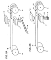
- Fig. 1A illustrates an implementation of a high performance, bulk ferromagnetic iron metal magnetic component 10 having a three-dimensional generally rectangular shape.
- the magnetic component 10 includes a plurality of substantially similarly shaped layers of ferromagnetic high saturation induction metal strip material 20 that are laminated together by adhesive bonding.
- the magnetic component depicted in Fig. 1B has a three-dimensional generally trapezoidal shape and includes a plurality of layers of ferromagnetic high saturation induction metal strip material 20 that are each substantially the same size and shape and that are laminated together by adhesive bonding.
- the magnetic component depicted in Fig. 1C includes two oppositely disposed arcuate surfaces 12.
- the component 10 is constructed of a plurality of substantially similarly shaped layers of ferromagnetic high saturation induction metal strip material 20 that are laminated together by adhesive bonding.
- Implementations of the bulk metal magnetic component 10 are generally three-dimensional polyhedrons, and their shapes may include a generally rectangular, square or trapezoidal prism.
- the component 10 may have at least one arcuate surface 12, and as shown may include two arcuate surfaces 12 disposed opposite each other.
- the shapes shown in Figs. 1A to 1C are exemplary only, and the aspect ratio of the height to width to length or arc length of such components may vary widely depending on the application.
- a three-dimensional magnetic component 10 constructed in accordance with the present invention exhibits low core loss.
- f an excitation frequency
- B max a peak induction level
- L 0.0135 f (B max ) 1.9 + 0.000108 f 1.6 (B max ) 1.92
- the core loss, the excitation frequency and the peak induction level being measured in watts per kilogram, hertz, and teslas, respectively.
- the magnetic component may have (i) a core-loss of less than or approximately equal to 1 watt-per-kilogram of magnetic material when operated at a frequency of approximately 60 Hz and at a flux density of approximately 1.0 Tesla (T); (ii) a core-loss of less than or approximately equal to 20 watts-per-kilogram of magnetic material when operated at a frequency of approximately 1000 Hz and at a flux density of approximately 1.0 T, or (iii) a core-loss of less than or approximately equal to 105 watt-per-kilogram of magnetic metal material when operated at a frequency of approximately 20,000 Hz and at a flux density of approximately 0.30T.
- the reduced core loss of the component advantageously improves the efficiency of an electrical device that incorporates such components.
- the low values of core loss make the bulk magnetic component especially suited for applications wherein the component is subjected to a high frequency magnetic excitation, e.g., excitation occurring at a frequency of at least about 100 Hz.
- a high frequency magnetic excitation e.g., excitation occurring at a frequency of at least about 100 Hz.
- the inherent high core loss of conventional steels at high frequency renders them unsuitable for use in devices requiring such high frequency excitations.
- the present invention also provides a method of constructing a bulk high performance metal magnetic component.
- a roll 30 of ferromagnetic high saturation induction metal strip material is cut into a plurality of strips 20 having the same shape and size using, for example, cutting blades 40.
- the strips 20 are stacked to form a bar 50 of stacked high saturation induction metal strip material.
- the bar 50 is impregnated with an epoxy resin and cured to adhesively bond together the strips.
- the bar 50 can be cut along the lines 52 depicted in Fig. 3 to produce a plurality of generally three-dimensional parts having a generally rectangular, square or trapezoidal prism shape.
- the cutting means may alternately be a cutting wheel, a water jet, an electro-chemical grinding machine, and an electro-discharge machine or other suitable device.
- the component 10 may include at least one arcuate surface 12, as shown in Fig. 1C .
- a bulk high saturation induction metal magnetic component 10 is formed by winding a single ferromagnetic high saturation induction metal strip 22 or a group of ferromagnetic high saturation induction metal strips 22 around a generally rectangular mandrel 60 to form a generally rectangular wound core 70.
- the height of the short sides 74 of the core 70 is preferably approximately equal to the desired length of the finished bulk high saturation induction metal magnetic component 10.
- the core 70 is impregnated with an epoxy resin and cured to adhesively bond together the layers of the core.
- Two components 10 may be formed by cutting the short sides 74, leaving the radiused corners 76 connected to the long sides 78a and 78b.
- Additional magnetic components 10 may be formed by removing the radiused corners 76 from the long sides 78a and 78b, and cutting the long sides 78a and 78b at a plurality of locations, indicated by the dashed lines 72.
- the bulk high saturation induction metal component 10 has a generally three-dimensional rectangular shape, although other three-dimensional shapes are contemplated, for example, shapes having at least one trapezoidal or square face.
- the bulk high saturation induction metal magnetic component 10 can be cut from bars 50 of stacked ferromagnetic high saturation induction metal strip or from cores 70 of wound ferromagnetic high saturation induction metal strip using many different cutting technologies.
- the component 10 may be cut from the bar 50 or core 70 using a cutting blade or wheel. Alternately, the component 10 may be cut by electro-discharge machining, electro-chemical grinding, or with a water jet or other suitable cutting device.
- FIG. 6A Yet another embodiment for illustrating the method is shown in Fig. 6A .
- a high saturation induction metal strip is first annealed in an inert gas box oven (not shown) at a pre-selected temperature and for a pre-selected time sufficient to effect improvement of its magnetic properties and achieve a desired level of superlattice ordering of the alloy strip.
- the heat treated strip 32 is then fed from roll 30 into an automatic high-speed punch press 38 and between a punch 40 and an open-bottom die 41.
- the punch is driven into the die causing a lamination 20 of the required shape to be formed.
- Lamination 20 then falls or is transported out of die 41 into a collection device 49 and punch 40 is retracted.
- the collection device 49 may be a conveyor belt as shown in Fig.
- each lamination 20 may then be manually or automatically coated with an anaerobic adhesive and the laminations stacked in registry in an alignment fixture (not shown). The adhesive is allowed to cure.
- the now laminated stack 10 (see Figs. 1A-1C ) of laminations 20 is removed from the alignment fixture and the surface of stack 10 finished by removing any excess adhesive.
- FIG. 6B Still another embodiment is shown in Fig. 6B .
- a roll 30 of ferromagnetic metal strip material 32 is fed continuously into an automatic high-speed punch press 38 and between a punch 40 and an open-bottom die 41.
- the punch 40 is driven into the die 41 causing a lamination 20 of the required shape to be formed.
- Lamination 20 then falls into or is transported to a collecting magazine 48 and punch 40 is retracted.
- a skeleton 33 of strip material 32 remains and contains holes 34 from which laminations 20 have been removed. Skeleton 33 is collected on takeup spool 31. After each punching action is accomplished, the strip 32 is indexed to prepare the strip for another punching cycle.
- Strip material 32 may be fed into press 38 either in a single layer or in multiple layers (not illustrated), either from multiple payoffs or by prior pre-spooling of multiple layers. Use of multiple layers of strip material 32 advantageously reduces the number of punch strokes required to produce a given number of laminations 20.
- the punching process is continued and a plurality of laminations 20 are collected in magazine 48 in sufficiently well-aligned registry. After a requisite number of laminations 20 are punched and deposited into magazine 48, the operation of punch press 38 is interrupted. The requisite number may either be pre-selected or may be determined by the height or weight of laminations 20 received in magazine 48. Magazine 48 is then removed from punch press 38 for further processing.
- magazine 48 and laminations 20 contained therein are placed in an inert gas box oven (not shown) and heat-treated by heating them to a pre-selected temperature and holding them at that temperature for a pre-selected time sufficient to effect improvement of its magnetic properties by relieving residual stresses in the alloy.
- the magazine and laminations are then cooled to ambient temperature.
- a low-viscosity, heat-activated epoxy (not shown) is allowed to infiltrate the spaces between laminations 20 which are maintained in registry by the walls of magazine 48.
- Epoxy is then activated by placing the entire magazine 48 and laminations 20 contained therein in a curing oven for a time sufficient to effect the cure of the epoxy.
- the now laminated stack 10 see Figs.
- laminations 20 is removed and the surface of stack 10 finished by removing any excess epoxy.
- an optional finishing step may be accomplished to finish the component. Such a finishing operation may include removing excess adhesive, giving the component a suitable surface finish, and/or giving the component its desired component dimensions.
- the present invention also provides a poleface magnet comprising at least one high performance bulk magnetic component.
- a poleface magnet 100 comprising a plurality of bulk high performance magnetic components.
- a generally cylindrical poleface magnet 100 is assembled by placing the components in a cylindrical nonmagnetic housing 102 in a predetermined alignment, filling the housing and the gaps between components with an epoxy potting compound 104, and curing the assembly. Alternately, a housing may not be required.
- the poleface magnet 100 includes a central bulk high performance magnetic component 106 which is approximately a square prismatic shape and four subordinate peripheral components, 108, 110, 112 and 114. The outside surface of each peripheral component 108, 110, 112 and 114 is approximately a 90 degree arcuate segment, so that the poleface magnet 100 assumes a substantially circular shape when constructed as shown.
- a number of crystalline ferromagnetic alloys having a combination of high saturation induction, high magnetic permeability, and low core loss may be used in constructing the high performance, bulk metal magnetic component of the invention.
- the alloy is an iron-base alloy having high silicon of 4-11%. Alloy containing 6-7% Si may be more suitable for some applications. Fe-Ni base alloys of Fe-Ni with 35-70% nickel and saturation induction greater than 1.2 T may also be suitable. The saturation induction values of Fe-Ni alloys with 45-55% Ni are especially high, e.g. over 1.5 T. Alloys of Fe-Co with have very high saturation induction but tend to have higher core loss than either Fe-Ni or Fe-Si alloys. Fe-Si-A1 alloys such as Sendust have lower saturation induction (e.g. about 1.2T) but advantageously have very low magnetostriction, low core loss, and high permeability.
- the layers of strip material optionally may have an insulative coating to further reduce their eddy current losses.
- Phosphate or other inorganic or organ coatings known in the electrical art may be suitable for such an application.
- a suitable alloy for use in fabricating three-dimensional high performance bulk metal magnetic components is ferromagnetic at the temperature at which the component is to be used.
- a ferromagnetic material is one which exhibits strong, long-range coupling and spatial alignment of the magnetic moments of its constituent atoms at a temperature below a characteristic temperature (generally termed the Curie temperature) of the material. It is preferred that the Curie temperature of material to be used in a device operating at room temperature be at least about 200°C and preferably at least about 375°C. Devices may be operated at other temperatures, including down to cryogenic temperatures or at elevated temperatures, if the material to be incorporated therein has an appropriate Curie temperature.
- a ferromagnetic material may further be characterized by its saturation induction or equivalently, by its saturation flux density or magnetization.
- the alloy described herein as suitable has a saturation induction of at least about 1.2 tesla (T) and, more suitably, a saturation induction of at least about 1.5 T.
- the alloy also has high electrical resistivity, which may be at least about 30 ⁇ -cm.
- the ferromagnetic material may be formed by using a chemical vapor deposition (CVD) process to produce a high quality ferromagnetic strip.
- CVD chemical vapor deposition
- sheets of high silicon content Fe-base alloys can be produced by subjecting steel strip to siliconization at temperatures between 1023° and 1200° centigrade by CVD in a non-oxidizing gas atmosphere containing SiCl 4 , and then performing a diffusion treatment to diffuse Si uniformly through the steel strip. The resulting steel strip is then cooled and coiled and ready for use.
- a rapid solidification process may be used to create a high silicon steel strip.
- a high silicon steel melt is first prepared that may be in the range of about 4-11 percent weight silicon and may contain incidental impurities.
- the high silicon steel melt is rapidly cooled (at a rate on the order of 10 3 to 10 6 centigrade per second) on a cooling substrate to about 400°C to form the thin metal strip.
- the resulting metal strip material has been know to exhibit excellent magnetic properties
- Non-oriented, ferromagnetic high silicon iron alloys suitable for constructing the magnetic component have recently become available commercially, for example, the SuperE and SuperHF series of high silicon steel materials sold by Nippon Kokan.
- the former is a 6.5%Si steel alloy
- the latter an alloy with a gradient of Si concentration through the strip thickness ranging from 6.5% Si at the surface to 4% at mid-strip. Both are sold as continuous strip material as thin as 0.05 mm with average saturation flux densities of 1.8 and 1.85 T, respectively.
- Ternary Fe-Si-A1 alloys such as Sendust may also be suitable for certain poleface applications because of their permeability and core loss. Alloys consisting essentially of 4-7% A1, 8-11% Si, and the balance Fe and incidental impurities may be suitable, with a composition of 5.5% A1 and 9.5% Si being preferred.
- Known techniques for preparing Fe-Si-A1 alloy include rapid solidification, squeeze casting, and powder metallurgy.
- An Fe-Ni alloy having 45-55% Ni suitable for the invention is sold by National Arnold under the tradename DeltaMax.
- Round-loop versions of the Fe-Ni alloys are preferred, since they exhibit lower core losses than versions processed to give high B-H loop squareness.
- adhesive bonding means may be used to adhere a plurality of layers of metal material to each other, thereby giving the component sufficient structural integrity for handling, use, or incorporation into a larger structure.
- the adhesive means may effect adherence of only a portion of the surfaces of adjacent metal layers, such as a portion near the periphery thereof.
- the adhesive means may effect adherence of at least 50% of the area of the adjacent layers, and more suitably, substantially all the area.
- the adhesive bonding means generally includes use of an adhesive.
- a variety of adhesives may be suitable, including epoxies, varnishes, anaerobic adhesives, and room-temperature-vulcanized (RTV) silicone materials.
- Adhesives desirably have low viscosity, low shrinkage, low elastic modulus, high peel strength, and high dielectric strength.
- Epoxies may be either multi-part, whose curing is chemically activated, or single-part, whose curing is activated thermally or by exposure to ultraviolet radiation. Suitable methods for applying the adhesive include, but are not limited to, dipping, spraying, brushing, and electrostatic deposition. In strip or ribbon form metal may also be coated by passing it over rods or rollers which transfer adhesive to the metal.
- Rollers or rods having a textured surface are especially effective in transferring a uniform coating of adhesive onto the metal.
- the adhesive may be applied to individual layers of metal, one at a time.
- the adhesive means may be applied to all of the layers of metal collectively, after they have been stacked.
- the stack is impregnated by capillary flow of the adhesive between the laminations.
- the stack may be placed either in a vacuum or under hydrostatic pressure to effect more complete filling. Such procedures result in minimizing the total volume of adhesive added, thus resulting in a well-controlled, high stacking factor.
- the lamination of the layers of the component may be accomplished by overmolding stacked layers or by mechanically restraining the layers with bands or other similar means.
- the bulk high saturation induction metal magnetic components described herein are especially suited for tiles for poleface magnets used in high performance MRI systems, in television and video systems, and in electron and ion beam systems.
- the disclosed techniques result in simplified magnetic component manufacturing and reduce manufacturing time. Stresses otherwise encountered during the construction of bulk high saturation induction metal components are minimized and magnetic performance of the finished components is optimized.
- An electromagnet system comprising an electromagnet having one or more poleface magnets is commonly used to produce a time-varying magnetic field in the gap of the electromagnet.
- the time-varying magnetic field may be a purely AC field, i.e. a field whose time average value is zero.
- the time varying field may have a non-zero time average value conventionally denoted as the DC component of the field.
- the at least one poleface magnet is subjected to the time-varying magnetic field. As a result the pole face magnet is magnetized and demagnetized with each excitation cycle.
- the time-varying magnetic flux density or induction within the poleface magnet causes the production of heat from core loss therein.
- the total loss is a consequence both of the core loss which would be produced within each component if subjected in isolation to the same flux waveform and of the loss attendant to eddy currents circulating in paths which provide electric continuity between the components.
- Bulk high performance magnetic components will magnetize and demagnetize more efficiently than components made from other conventional iron-base magnetic metals.
- the high performance, low loss metal component When used as a pole magnet, the high performance, low loss metal component will generate less heat than a comparable component made from another iron-base magnetic metal when the two components are magnetized at identical induction and excitation frequency.
- a suitable ferromagnetic metal has a saturation induction of at least about 1.2 T and preferably at least about 1.7 T.
- High silicon iron alloy may have a saturation induction of up to about 1.8 T. Such saturation inductions are significantly higher than those of other low loss soft magnetic materials such as high Ni permalloy alloys, which are typically 0.6 - 0.9 T.
- the metal component can therefore be designed to operate 1) at a lower operating temperature; 2) at higher induction to achieve reduced size and weight; or, 3) at higher excitation frequency to achieve reduced size and weight, or to achieve superior signal resolution, when compared to magnetic components made from other conventional iron-base magnetic metals.
- the alloy strip is no more than 100 ⁇ m (0.004") thick and has an electrical resistivity of 30 ⁇ -cm or more.
- Commercial 50Ni-Fe alloys generally have saturation inductions of at least 1.5 T and resistivities of at least 30 ⁇ -cm.
- the alloy strip is composed of high silicon iron alloy no more than 50 ⁇ m (0.002") thick and with an electrical resistivity of 50-80 ⁇ -cm or more.
- Core loss may be defined as that dissipation of energy which occurs within a ferromagnetic material as the magnetization thereof is changed with time.
- the core loss of a given magnetic component is generally determined by cyclically exciting the component. A time-varying magnetic field is applied to the component to produce therein a corresponding time variation of the magnetic induction or flux density.
- the excitation is generally chosen such that the magnetic induction varies sinusoidally with time at a frequency "f" and with a peak amplitude "B max .”
- the core loss is then determined by known electrical measurement instrumentation and techniques. Loss is conventionally reported as watts per unit mass or volume of the magnetic material being excited. It is known that loss increases monotonically with f and B max .
- the core loss behavior of the component described herein is best characterized by testing in a magnetically open circuit, i.e. a configuration in which magnetic flux lines must traverse an air gap. Such a test more closely simulates the behavior of the component when used in a circuit wherein one or more air gaps contribute a significant portion of the total circuit reluctance.
- fringing field effects and non-uniformity of the magnetic field may result in somewhat higher core losses, i.e. higher values of watts per unit mass or volume, than comparable material would show in a lower reluctance or closed circuit.
- the present bulk magnetic component advantageously exhibits low core loss over a wide range of flux densities and frequencies even in an open-circuit configuration.
- the total core loss of the presented low-loss bulk high saturation induction metal component includes contributions from hysteresis losses and eddy current losses. Each of these two contributions is a function of the peak magnetic induction B max and of the excitation frequency f.
- Prior art analyses of core losses in amorphous and high silicon iron metals have generally been restricted to data obtained for material in a closed magnetic circuit.
- a core loss equation such as that set forth above defines the required performance of the component of the invention.
- the parameters of this equation may be determined from a representative set of empirical test data points using numerical methods such as least squares fitting (also known as regression analysis).
- Known non-linear methods are required if the exponents n, m, and q are to be adjusted. Linear methods suffice if only c 1 and c 2 are to be determined.
- the measurement of the core loss of the present magnetic component can be carried out using various methods known in the art, including the ASTM methods cited above.
- Another method suited for measuring the present component comprises forming a magnetic circuit with the present magnetic component and a flux closure structure means.
- the magnetic circuit may comprise a plurality of magnetic components of the invention and a flux closure structure means.
- the flux closure structure means comprises soft magnetic material having high permeability and a saturation flux density at least equal to the flux density at which the component is to be tested.
- the soft magnetic material may have a saturation flux density at least equal to the saturation flux density of the component.
- the flux direction along which a component is to be tested generally defines first and second opposite faces of the component.
- the flux lines generally follow the plane of the high saturation induction metal strips, and emerge from the second opposing face.
- the flux closure structure means generally comprises a flux closure magnetic component.
- Such a component could be constructed as taught herein, but may also be made with other methods and with known materials.
- the flux closure magnetic component also has first and second opposing faces through which flux lines enter and emerge, generally normal to the respective planes thereof.
- the flux closure component opposing faces are substantially the same size and shape as compared to the respective faces of the magnetic component to which the flux closure component is mated during actual testing.
- the flux closure magnetic component is placed in mating relationship with its first and second faces closely proximate and substantially proximate to the first and second faces of the present magnetic component, respectively.
- Magnetomotive force is applied by passing current through a first winding encircling either the present magnetic component or the flux closure magnetic component.
- the resulting flux density is determined by Faraday's law from the voltage induced in a second winding encircling the magnetic component to be tested.
- the applied magnetic field is determined by Ampère's law from the magnetomotive force.
- the core loss is then computed from the applied magnetic field and the resulting flux density by conventional methods.
- a component 10 having a core loss which can be readily determined by the testing method described hereinafter.
- long side 78b of core 70 is appointed as magnetic component 10 for core loss testing.
- the remainder of core 70 serves as the flux closure structure means, which is generally C-shaped and comprises the four generally radiused corners 76, short sides 74 and long side 78a.
- Each of the cuts 72 which separate the radiused corners 76, the short sides 74, and long side 78a is optional.
- Only the cuts separating long side 78b from the remainder of core 70 are made. Cut surfaces formed by cutting core 70 to remove long side 78b define the opposite faces of the magnetic component and the opposite faces of the flux closure magnetic component.
- long side 78b is situated with its faces closely proximate and parallel to the corresponding faces defined by the cuts.
- the faces of long side 78b are substantially the same in size and shape as the faces of the flux closure magnetic component.
- Two copper wire windings (not shown) encircle long side 78b.
- An alternating current of suitable magnitude is passed through the first winding to provide a magnetomotive force that excites long side 78b at the requisite frequency and peak flux density.
- Flux lines in long side 78b and the flux closure magnetic component are generally within the plane of strips 22 and directed circumferentially.
- Voltage indicative of the time varying flux density within long side 78b is induced in the second winding. Core loss is determined by conventional electronic means from the measured values of voltage and current.
Landscapes
- Engineering & Computer Science (AREA)
- Power Engineering (AREA)
- Physics & Mathematics (AREA)
- Electromagnetism (AREA)
- Chemical & Material Sciences (AREA)
- Dispersion Chemistry (AREA)
- Manufacturing & Machinery (AREA)
- Manufacturing Cores, Coils, And Magnets (AREA)
- Soft Magnetic Materials (AREA)
- Hard Magnetic Materials (AREA)
- Powder Metallurgy (AREA)
Claims (15)
- Magnetische Massen-Komponente hoher Leistung mit geringem Kernverlust, die eine Vielheit im Wesentlichen ähnlich geformter Schichten von kristallinen, ferromagnetischen Metallstreifen und ein haftfähiges Bindemittel in Form eines Klebers umfasst, die haftfähig durch das haftfähige Bindemittel verbunden sind, um ein laminiertes polyedrisch geformtes Teil zu bilden, wobei die ferromagnetischen Metallstreifen eine Legierung auf Eisenbasis einschließen, die 4-11 Gewichtsprozent Si enthält und, wobei besagte magnetische Komponente, wenn mit einer Erregungsfrequenz "f' auf Spitzeninduktionspegel Bmax betrieben, einen Kernverlust von weniger als "L" hat, wobei L durch die Formel L = 0,0135 f (Bmax)1.9 + 0,000108 f1.6 (Bmax)1.92, gegeben ist, besagter Kernverlust, besagte Erregungsfrequenz und besagter Spitzeninduktionspegel in Watt pro Kilogramm, Hertz beziehungsweise Tesla gemessen sind.
- Magnetische Massen-Komponente hoher Leistung nach Anspruch 1, wobei die Komponente die Form von zumindest jeweils eines dreidimensionalen Polyeders mit zumindest einem rechteckigen Querschnitt, eines dreidimensionalen Polyeders mit zumindest einem trapezförmigen Querschnitt und eines dreidimensionalen Polyeders mit zumindest einem quadratischen Querschnitt aufweist.
- Magnetische Massen-Komponente hoher Leistung nach Anspruch 1, wobei die Komponente zumindest eine bogenförmige Oberfläche einschließt.
- Magnetische Massen-Komponente hoher Leistung nach Anspruch 1, wobei die magnetische Komponente einen Kernverlust von weniger als oder annähernd gleich 1 Watt pro Kilogramm von magnetischem Metallmaterial, bei Betrieb mit einer Frequenz von annähernd 60 Hz und mit einer Flussdichte von annähernd 1,0 T, hat.
- Magnetische Massen-Komponente hoher Leistung nach Anspruch 1, wobei besagte magnetische Komponente einen Kernverlust von weniger als oder annähernd gleich 20 Watt pro Kilogramm von magnetischem Metallmaterial, bei Betrieb mit einer Frequenz von annähernd 1.000 Hz und mit einer Flussdichte von annähernd 1,0 T, hat.
- Magnetische Massen-Komponente hoher Leistung nach Anspruch 1, wobei besagte magnetische Komponente einen Kernverlust von weniger als oder annähernd gleich 105 Watt pro Kilogramm von magnetischem Metallmaterial, bei Betrieb mit einer Frequenz von annähernd 20.000 Hz und mit einer Flussdichte von annähernd 0,30 T, hat.
- Magnetische Massen-Komponente hoher Leistung nach Anspruch 1, wobei besagtes haftfähiges Bindemittel zumindest einen Klebstoff einschließt, der aus der Gruppe bestehend aus Epoxiden, Lacken, anaerobischen Klebstoffen und bei (RTV) Raumtemperatur vulkanisierten Silikonmaterialien ausgewählt wurde.
- Polflächenmagnet hoher Leistung, der zumindest eine magnetische Komponente, jede wie in Anspruch 1 definiert, umfasst.
- Verfahren zur Konstruktion einer magnetischen Massen-Komponente hoher Leistung wie in Anspruch definiert 1, umfassend:(a) Schneiden kristallinen, ferromagnetischen Metallstreifenmaterials aus der Legierung auf Eisenbasis, die 4-11 Gewichtsprozent Si enthält, um eine Vielheit von Streifen mit einer vorbestimmten Länge zu bilden;(b) Stapeln der Streifen, um einen Stab aus gestapeltem ferromagnetischem Metallstreifenmaterial zu bilden;(c) Imprägnieren des gestapelten Stabs mit einem haftfähigen Bindemittel und Aktivieren des haftfähigen Mittels, um das haftfähige Bindemittel zu bilden, um die geschnittenen Streifen zu laminieren; und(d) Schneiden des gestapelten Stabs an vorbestimmten Längen, um eine Vielheit von polyedrisch geformten magnetischen Komponenten bereitzustellen.
- Verfahren nach Anspruch 9, wobei der Schritt (d) das Schneiden des gestapelten Stabs unter Verwendung von Schneidmitteln umfasst, die zumindest jeweils eine Schneidklinge, eine Trennschleifscheibe, einen Wasserstrahl, eine elektrochemische Schleifmaschine und eine Funkenerosionsmaschine einschließen.
- Verfahren zur Konstruktion einer magnetischen Massen-Komponente hoher Leistung wie in Anspruch definiert 1, umfassend:(a) Wickeln kristallinen, ferromagnetischen Metallstreifenmaterials, das zumindest aus der Legierung auf Eisenbasis besteht, die 4-11 Gewichtsprozent Si enthält, um einen Dorn, um einen generell rechteckigen Kern mit generell abgerundeten Ecken zu bilden;(b) Imprägnieren des generell rechteckigen Kerns mit einem haftfähigen Bindemittel und Aktivieren des Klebstoffs, um das haftfähige Bindemittel zu bilden, um die Schichten zu laminieren;(c) Schneiden der kurzen Seiten des generell rechteckigen Kerns, um zwei polyedrisch geformte magnetische Komponenten zu bilden;(d) Entfernen der generell abgerundeten Ecken von den langen Seiten des generell rechteckigen Kerns; und(e) Schneiden der langen Seiten des generell rechteckigen Kerns, um eine Vielheit von besagten magnetischen Komponenten zu bilden.
- Verfahren nach Anspruch 11, wobei zumindest einer der Schritte (c) und (e) das Schneiden von ferromagnetischem Metallstreifenmaterial unter Verwendung von zumindest jeweils einer Schneidklinge, einer Trennschleifscheibe, einem Wasserstrahl, einer elektrochemischen Schleifmaschine und einer Funkenerosionsmaschine umfasst.
- Verfahren zur Konstruktion einer magnetischen Massen-Komponente hoher Leistung wie in Anspruch definiert 1, das folgende Schritte umfasst:(a) Stanzen kristallinen, ferromagnetischen Metallstreifen-Ausgangsmaterials, das aus zumindest der Legierung auf Eisenbasis besteht, die 4-11 Gewichtsprozent Si enthält, um eine Vielheit von Lamellen einer vorbestimmten Form zu bilden;(b) Stapeln und Registrieren der Lamellen, um einen Stapel mit dreidimensionaler Form zu bilden; und(c) Auftragen und Aktivieren des haftfähigen Mittels, um das haftfähige Bindemittel zu bilden, um die Lamellen zum Formen der Komponente miteinander zu verkleben.
- Polflächenmagnet, der zumindest eine magnetische Massen-Komponente hoher Leistung mit geringem Kernverlust, wie in einem beliebigen der Ansprüche 1 bis 7 definiert, umfasst.
- Magnet-Resonanz-Abbildungsgerät, das einen Polflächenmagnet, wie in Anspruch 14 definiert, umfasst.
Applications Claiming Priority (3)
| Application Number | Priority Date | Filing Date | Title |
|---|---|---|---|
| US22103500P | 2000-07-27 | 2000-07-27 | |
| US221035P | 2000-07-27 | ||
| PCT/US2001/041384 WO2002011158A2 (en) | 2000-07-27 | 2001-07-24 | Bulk metal magnetic component |
Publications (2)
| Publication Number | Publication Date |
|---|---|
| EP1303861A2 EP1303861A2 (de) | 2003-04-23 |
| EP1303861B1 true EP1303861B1 (de) | 2011-11-16 |
Family
ID=22826067
Family Applications (1)
| Application Number | Title | Priority Date | Filing Date |
|---|---|---|---|
| EP01959809A Expired - Lifetime EP1303861B1 (de) | 2000-07-27 | 2001-07-24 | Massen-komponente aus magnetischen metall |
Country Status (8)
| Country | Link |
|---|---|
| US (1) | US6744342B2 (de) |
| EP (1) | EP1303861B1 (de) |
| JP (2) | JP2004511898A (de) |
| AT (1) | ATE534129T1 (de) |
| AU (1) | AU2001281328A1 (de) |
| MY (1) | MY129107A (de) |
| TW (1) | TW511104B (de) |
| WO (1) | WO2002011158A2 (de) |
Families Citing this family (19)
| Publication number | Priority date | Publication date | Assignee | Title |
|---|---|---|---|---|
| US6873239B2 (en) * | 2002-11-01 | 2005-03-29 | Metglas Inc. | Bulk laminated amorphous metal inductive device |
| US20060075623A1 (en) * | 2004-10-13 | 2006-04-13 | Dan Jones | Method of manufacture of metal components |
| CH698140B1 (de) * | 2006-01-20 | 2009-05-29 | Alstom Technology Ltd | Verfahren zur Digitalisierung dreidimensionaler Bauteile. |
| US7538650B2 (en) * | 2006-07-17 | 2009-05-26 | Smith International, Inc. | Apparatus and method for magnetizing casing string tubulars |
| EP2139011B1 (de) * | 2007-04-13 | 2015-08-26 | Hitachi Metals, Ltd. | Magnetkern für eine antenne, verfahren zur herstellung eines magnetkerns für eine antenne und antenne |
| US20110234347A1 (en) * | 2010-03-24 | 2011-09-29 | Aspect Magnet Technologies Ltd. | Pole piece for permanent magnet mri systems |
| US8209850B2 (en) * | 2010-03-25 | 2012-07-03 | Tempel Steel Company | Method for manufacturing pencil cores |
| KR101456952B1 (ko) * | 2013-05-30 | 2014-11-07 | 주식회사 리플렉스 | 승압 트랜스포머용 마그네틱 코어 |
| US10760563B2 (en) | 2015-09-07 | 2020-09-01 | Panasonic Intellectual Property Management Co., Ltd. | Refrigerant compressor and refrigeration device including refrigerant compressor |
| JP2017053341A (ja) * | 2016-04-15 | 2017-03-16 | パナソニックIpマネジメント株式会社 | 冷媒圧縮機およびそれを用いた冷凍装置 |
| US11626234B2 (en) * | 2016-09-30 | 2023-04-11 | Aperam | Transformer core for a cut-and-stack type transformer and transformer including same |
| TWI628899B (zh) * | 2017-03-28 | 2018-07-01 | 富田電機股份有限公司 | Motor core process and structure |
| CN109004773A (zh) * | 2018-09-12 | 2018-12-14 | 宁波安信数控技术有限公司 | 一种磁钢结构 |
| CA3061931A1 (en) * | 2019-11-19 | 2021-05-19 | Youliang HE | Oriented magnetic core lamination and method of manufacturing |
| EP3916743A1 (de) * | 2020-05-29 | 2021-12-01 | ABB Power Grids Switzerland AG | Hybrider transformatorkern und verfahren zur herstellung eines transformatorkerns |
| US20250332653A1 (en) * | 2021-02-19 | 2025-10-30 | Temper Ip, Llc | System for heating components for curing and bonding multi-component structures |
| CN113470944A (zh) * | 2021-05-26 | 2021-10-01 | 深圳大学 | 一种非晶磁性材料高频变压器铁芯及其制造方法 |
| US11961670B1 (en) * | 2022-10-06 | 2024-04-16 | Delphi Technologies Ip Limited | System including a bent capacitor bus bar |
| CN115647760B (zh) * | 2022-10-26 | 2025-12-16 | 安徽金寨将军磁业有限公司 | 一种永磁铁氧体磁瓦合金凹模的加工方法 |
Family Cites Families (20)
| Publication number | Priority date | Publication date | Assignee | Title |
|---|---|---|---|---|
| GB1326766A (en) | 1969-09-19 | 1973-08-15 | Gen Electric | Laminated magnetic cores for electric induction apparatus |
| DE2856795C2 (de) * | 1977-12-30 | 1984-12-06 | Noboru Prof. Sendai Tsuya | Verwendung einer Stahlschmelze für ein Verfahren zum Stranggießen eines dünnen Bandes |
| SE448381B (sv) * | 1978-09-19 | 1987-02-16 | Tsuya Noboru | Sett att framstella ett tunt band av kiselstal, tunt kiselstalband och anvendning av dylikt |
| JPS5612705A (en) | 1979-07-13 | 1981-02-07 | Toshiba Corp | Raw material for magnetic head core |
| DE3566185D1 (en) * | 1984-04-11 | 1988-12-15 | Sumitomo Spec Metals | Magnetic field generating device for nmr-ct |
| JPS62124704A (ja) * | 1985-11-26 | 1987-06-06 | Kawasaki Steel Corp | 磁気特性および層間絶縁性に優れた巻コアおよびその製造方法 |
| JPS62227078A (ja) * | 1986-03-28 | 1987-10-06 | Nippon Kokan Kk <Nkk> | 連続ラインにおける高珪素鋼帯の製造方法 |
| US4827235A (en) * | 1986-07-18 | 1989-05-02 | Kabushiki Kaisha Toshiba | Magnetic field generator useful for a magnetic resonance imaging instrument |
| US4990197A (en) * | 1986-08-01 | 1991-02-05 | Allied-Signal, Inc. | Heat treatment of rapidly quenched Fe-6.5 wt % Si ribbon |
| US4865657A (en) * | 1986-08-01 | 1989-09-12 | Das Santosh K | Heat treatment of rapidly quenched Fe-6.5 wt % Si ribbon |
| JPS63241905A (ja) * | 1987-03-27 | 1988-10-07 | Sumitomo Special Metals Co Ltd | 磁界発生装置 |
| JPH02121309A (ja) | 1988-10-31 | 1990-05-09 | Matsushita Electric Ind Co Ltd | Fe−Si−Al磁芯の製造法及びそれを用いた磁気ヘッド |
| SG43224A1 (en) * | 1990-09-29 | 1997-10-17 | Sumitomo Spec Metals | Magnetic field generating device used for MRI |
| US5124651A (en) * | 1990-10-24 | 1992-06-23 | Fonar Corporation | Nuclear magnetic resonance scanners with composite pole facings |
| US5354389A (en) * | 1991-07-29 | 1994-10-11 | Nkk Corporation | Method of manufacturing silicon steel sheet having grains precisely arranged in Goss orientation |
| JPH09275021A (ja) * | 1996-04-04 | 1997-10-21 | Nkk Corp | 磁気特性の優れた低騒音鉄心 |
| JPH10121212A (ja) | 1996-10-16 | 1998-05-12 | Nippon Steel Corp | 一方向性電磁鋼板およびその製造方法 |
| JP3322600B2 (ja) | 1997-03-31 | 2002-09-09 | 三洋電機株式会社 | 電流調整回路 |
| US6420813B1 (en) * | 1998-11-06 | 2002-07-16 | Alliedsignal Inc. | Bulk amorphous metal magnetic components for electric motors |
| US6331363B1 (en) | 1998-11-06 | 2001-12-18 | Honeywell International Inc. | Bulk amorphous metal magnetic components |
-
2001
- 2001-07-23 US US09/911,355 patent/US6744342B2/en not_active Expired - Fee Related
- 2001-07-24 AU AU2001281328A patent/AU2001281328A1/en not_active Abandoned
- 2001-07-24 EP EP01959809A patent/EP1303861B1/de not_active Expired - Lifetime
- 2001-07-24 WO PCT/US2001/041384 patent/WO2002011158A2/en not_active Ceased
- 2001-07-24 JP JP2002516794A patent/JP2004511898A/ja active Pending
- 2001-07-24 AT AT01959809T patent/ATE534129T1/de active
- 2001-07-25 MY MYPI20013527A patent/MY129107A/en unknown
- 2001-07-27 TW TW090118469A patent/TW511104B/zh not_active IP Right Cessation
-
2011
- 2011-01-11 JP JP2011002988A patent/JP2011139075A/ja active Pending
Also Published As
| Publication number | Publication date |
|---|---|
| MY129107A (en) | 2007-03-30 |
| WO2002011158A3 (en) | 2002-04-25 |
| US20030201864A1 (en) | 2003-10-30 |
| JP2011139075A (ja) | 2011-07-14 |
| ATE534129T1 (de) | 2011-12-15 |
| TW511104B (en) | 2002-11-21 |
| AU2001281328A1 (en) | 2002-02-13 |
| US6744342B2 (en) | 2004-06-01 |
| EP1303861A2 (de) | 2003-04-23 |
| JP2004511898A (ja) | 2004-04-15 |
| WO2002011158A2 (en) | 2002-02-07 |
Similar Documents
| Publication | Publication Date | Title |
|---|---|---|
| EP1277216B1 (de) | Gestanzte massen-komponente aus amorphem magnetischen metall | |
| EP1303861B1 (de) | Massen-komponente aus magnetischen metall | |
| US7011718B2 (en) | Bulk stamped amorphous metal magnetic component | |
| CN101027733B (zh) | 大块层压非晶体金属感应装置 | |
| US7235910B2 (en) | Selective etching process for cutting amorphous metal shapes and components made thereof | |
| EP1240700B1 (de) | Räumlich ausgedehnte bauteile aus magnetisch leitenden amorphen metallen für elektromotoren | |
| US6346337B1 (en) | Bulk amorphous metal magnetic component | |
| CN1735948B (zh) | 大块非晶体金属感应装置 | |
| EP1127359B1 (de) | Amorphe magnetische massenmetallgegenstände | |
| US6348275B1 (en) | Bulk amorphous metal magnetic component | |
| HK1063529B (en) | Bulk amorphous metal magnetic component |
Legal Events
| Date | Code | Title | Description |
|---|---|---|---|
| PUAI | Public reference made under article 153(3) epc to a published international application that has entered the european phase |
Free format text: ORIGINAL CODE: 0009012 |
|
| 17P | Request for examination filed |
Effective date: 20030124 |
|
| AK | Designated contracting states |
Designated state(s): AT BE CH CY DE DK ES FI FR GB GR IE IT LI LU MC NL PT SE TR |
|
| AX | Request for extension of the european patent |
Extension state: AL LT LV MK RO SI |
|
| RAP1 | Party data changed (applicant data changed or rights of an application transferred) |
Owner name: METGLAS, INC. |
|
| 17Q | First examination report despatched |
Effective date: 20041027 |
|
| 17Q | First examination report despatched |
Effective date: 20041027 |
|
| GRAP | Despatch of communication of intention to grant a patent |
Free format text: ORIGINAL CODE: EPIDOSNIGR1 |
|
| GRAS | Grant fee paid |
Free format text: ORIGINAL CODE: EPIDOSNIGR3 |
|
| GRAA | (expected) grant |
Free format text: ORIGINAL CODE: 0009210 |
|
| AK | Designated contracting states |
Kind code of ref document: B1 Designated state(s): AT BE CH CY DE DK ES FI FR GB GR IE IT LI LU MC NL PT SE TR |
|
| REG | Reference to a national code |
Ref country code: GB Ref legal event code: FG4D |
|
| REG | Reference to a national code |
Ref country code: CH Ref legal event code: EP |
|
| REG | Reference to a national code |
Ref country code: IE Ref legal event code: FG4D |
|
| REG | Reference to a national code |
Ref country code: DE Ref legal event code: R096 Ref document number: 60145680 Country of ref document: DE Effective date: 20120126 |
|
| REG | Reference to a national code |
Ref country code: NL Ref legal event code: VDEP Effective date: 20111116 |
|
| PG25 | Lapsed in a contracting state [announced via postgrant information from national office to epo] |
Ref country code: NL Free format text: LAPSE BECAUSE OF FAILURE TO SUBMIT A TRANSLATION OF THE DESCRIPTION OR TO PAY THE FEE WITHIN THE PRESCRIBED TIME-LIMIT Effective date: 20111116 Ref country code: SE Free format text: LAPSE BECAUSE OF FAILURE TO SUBMIT A TRANSLATION OF THE DESCRIPTION OR TO PAY THE FEE WITHIN THE PRESCRIBED TIME-LIMIT Effective date: 20111116 Ref country code: PT Free format text: LAPSE BECAUSE OF FAILURE TO SUBMIT A TRANSLATION OF THE DESCRIPTION OR TO PAY THE FEE WITHIN THE PRESCRIBED TIME-LIMIT Effective date: 20120316 Ref country code: BE Free format text: LAPSE BECAUSE OF FAILURE TO SUBMIT A TRANSLATION OF THE DESCRIPTION OR TO PAY THE FEE WITHIN THE PRESCRIBED TIME-LIMIT Effective date: 20111116 Ref country code: GR Free format text: LAPSE BECAUSE OF FAILURE TO SUBMIT A TRANSLATION OF THE DESCRIPTION OR TO PAY THE FEE WITHIN THE PRESCRIBED TIME-LIMIT Effective date: 20120217 |
|
| PG25 | Lapsed in a contracting state [announced via postgrant information from national office to epo] |
Ref country code: CY Free format text: LAPSE BECAUSE OF FAILURE TO SUBMIT A TRANSLATION OF THE DESCRIPTION OR TO PAY THE FEE WITHIN THE PRESCRIBED TIME-LIMIT Effective date: 20111116 |
|
| PG25 | Lapsed in a contracting state [announced via postgrant information from national office to epo] |
Ref country code: DK Free format text: LAPSE BECAUSE OF FAILURE TO SUBMIT A TRANSLATION OF THE DESCRIPTION OR TO PAY THE FEE WITHIN THE PRESCRIBED TIME-LIMIT Effective date: 20111116 |
|
| REG | Reference to a national code |
Ref country code: AT Ref legal event code: MK05 Ref document number: 534129 Country of ref document: AT Kind code of ref document: T Effective date: 20111116 |
|
| PLBE | No opposition filed within time limit |
Free format text: ORIGINAL CODE: 0009261 |
|
| STAA | Information on the status of an ep patent application or granted ep patent |
Free format text: STATUS: NO OPPOSITION FILED WITHIN TIME LIMIT |
|
| 26N | No opposition filed |
Effective date: 20120817 |
|
| REG | Reference to a national code |
Ref country code: DE Ref legal event code: R097 Ref document number: 60145680 Country of ref document: DE Effective date: 20120817 |
|
| PG25 | Lapsed in a contracting state [announced via postgrant information from national office to epo] |
Ref country code: AT Free format text: LAPSE BECAUSE OF FAILURE TO SUBMIT A TRANSLATION OF THE DESCRIPTION OR TO PAY THE FEE WITHIN THE PRESCRIBED TIME-LIMIT Effective date: 20111116 |
|
| PG25 | Lapsed in a contracting state [announced via postgrant information from national office to epo] |
Ref country code: MC Free format text: LAPSE BECAUSE OF NON-PAYMENT OF DUE FEES Effective date: 20120731 |
|
| PG25 | Lapsed in a contracting state [announced via postgrant information from national office to epo] |
Ref country code: ES Free format text: LAPSE BECAUSE OF FAILURE TO SUBMIT A TRANSLATION OF THE DESCRIPTION OR TO PAY THE FEE WITHIN THE PRESCRIBED TIME-LIMIT Effective date: 20120227 |
|
| REG | Reference to a national code |
Ref country code: IE Ref legal event code: MM4A |
|
| PG25 | Lapsed in a contracting state [announced via postgrant information from national office to epo] |
Ref country code: FI Free format text: LAPSE BECAUSE OF FAILURE TO SUBMIT A TRANSLATION OF THE DESCRIPTION OR TO PAY THE FEE WITHIN THE PRESCRIBED TIME-LIMIT Effective date: 20111116 |
|
| PG25 | Lapsed in a contracting state [announced via postgrant information from national office to epo] |
Ref country code: IE Free format text: LAPSE BECAUSE OF NON-PAYMENT OF DUE FEES Effective date: 20120724 |
|
| PG25 | Lapsed in a contracting state [announced via postgrant information from national office to epo] |
Ref country code: TR Free format text: LAPSE BECAUSE OF FAILURE TO SUBMIT A TRANSLATION OF THE DESCRIPTION OR TO PAY THE FEE WITHIN THE PRESCRIBED TIME-LIMIT Effective date: 20111116 |
|
| PG25 | Lapsed in a contracting state [announced via postgrant information from national office to epo] |
Ref country code: LU Free format text: LAPSE BECAUSE OF NON-PAYMENT OF DUE FEES Effective date: 20120724 |
|
| PGFP | Annual fee paid to national office [announced via postgrant information from national office to epo] |
Ref country code: DE Payment date: 20140716 Year of fee payment: 14 Ref country code: CH Payment date: 20140714 Year of fee payment: 14 |
|
| PGFP | Annual fee paid to national office [announced via postgrant information from national office to epo] |
Ref country code: FR Payment date: 20140708 Year of fee payment: 14 Ref country code: GB Payment date: 20140723 Year of fee payment: 14 |
|
| PGFP | Annual fee paid to national office [announced via postgrant information from national office to epo] |
Ref country code: IT Payment date: 20140716 Year of fee payment: 14 |
|
| REG | Reference to a national code |
Ref country code: DE Ref legal event code: R119 Ref document number: 60145680 Country of ref document: DE |
|
| REG | Reference to a national code |
Ref country code: CH Ref legal event code: PL |
|
| GBPC | Gb: european patent ceased through non-payment of renewal fee |
Effective date: 20150724 |
|
| PG25 | Lapsed in a contracting state [announced via postgrant information from national office to epo] |
Ref country code: LI Free format text: LAPSE BECAUSE OF NON-PAYMENT OF DUE FEES Effective date: 20150731 Ref country code: GB Free format text: LAPSE BECAUSE OF NON-PAYMENT OF DUE FEES Effective date: 20150724 Ref country code: CH Free format text: LAPSE BECAUSE OF NON-PAYMENT OF DUE FEES Effective date: 20150731 Ref country code: DE Free format text: LAPSE BECAUSE OF NON-PAYMENT OF DUE FEES Effective date: 20160202 Ref country code: IT Free format text: LAPSE BECAUSE OF NON-PAYMENT OF DUE FEES Effective date: 20150724 |
|
| REG | Reference to a national code |
Ref country code: FR Ref legal event code: ST Effective date: 20160331 |
|
| PG25 | Lapsed in a contracting state [announced via postgrant information from national office to epo] |
Ref country code: FR Free format text: LAPSE BECAUSE OF NON-PAYMENT OF DUE FEES Effective date: 20150731 |