EP1304094B1 - Appariel de fabrication d'un tampon - Google Patents
Appariel de fabrication d'un tampon Download PDFInfo
- Publication number
- EP1304094B1 EP1304094B1 EP02022404A EP02022404A EP1304094B1 EP 1304094 B1 EP1304094 B1 EP 1304094B1 EP 02022404 A EP02022404 A EP 02022404A EP 02022404 A EP02022404 A EP 02022404A EP 1304094 B1 EP1304094 B1 EP 1304094B1
- Authority
- EP
- European Patent Office
- Prior art keywords
- pressing
- diameter
- tampon
- press
- jaws
- Prior art date
- Legal status (The legal status is an assumption and is not a legal conclusion. Google has not performed a legal analysis and makes no representation as to the accuracy of the status listed.)
- Expired - Lifetime
Links
- 230000002745 absorbent Effects 0.000 claims abstract description 3
- 239000002250 absorbent Substances 0.000 claims abstract description 3
- 230000002093 peripheral effect Effects 0.000 claims description 7
- 238000000034 method Methods 0.000 claims description 3
- 239000000463 material Substances 0.000 claims description 2
- 238000013022 venting Methods 0.000 claims 2
- 230000006835 compression Effects 0.000 abstract 1
- 238000007906 compression Methods 0.000 abstract 1
- 238000000465 moulding Methods 0.000 abstract 1
- 230000005540 biological transmission Effects 0.000 description 5
- 238000011143 downstream manufacturing Methods 0.000 description 2
- 239000000835 fiber Substances 0.000 description 2
- 229920000742 Cotton Polymers 0.000 description 1
- 230000002411 adverse Effects 0.000 description 1
- 230000015572 biosynthetic process Effects 0.000 description 1
- 238000005352 clarification Methods 0.000 description 1
- 239000002657 fibrous material Substances 0.000 description 1
- 230000012447 hatching Effects 0.000 description 1
- 230000003068 static effect Effects 0.000 description 1
Images


Classifications
-
- A—HUMAN NECESSITIES
- A61—MEDICAL OR VETERINARY SCIENCE; HYGIENE
- A61F—FILTERS IMPLANTABLE INTO BLOOD VESSELS; PROSTHESES; DEVICES PROVIDING PATENCY TO, OR PREVENTING COLLAPSING OF, TUBULAR STRUCTURES OF THE BODY, e.g. STENTS; ORTHOPAEDIC, NURSING OR CONTRACEPTIVE DEVICES; FOMENTATION; TREATMENT OR PROTECTION OF EYES OR EARS; BANDAGES, DRESSINGS OR ABSORBENT PADS; FIRST-AID KITS
- A61F13/00—Bandages or dressings; Absorbent pads
- A61F13/15—Absorbent pads, e.g. sanitary towels, swabs or tampons for external or internal application to the body; Supporting or fastening means therefor; Tampon applicators
- A61F13/20—Tampons, e.g. catamenial tampons; Accessories therefor
- A61F13/2082—Apparatus or processes of manufacturing
- A61F13/2085—Catamenial tampons
Definitions
- the invention relates to a device for producing a tampon from a cylindrical blank of any cross-sectional shape of absorbent material, with a pressing tool.
- EP 1 022 004 A1 known.
- the areas of the peripheral surface of the tampon blank which are located between the press cutters, on the other hand, are subjected to radial pressure by pressing shoulders which are set back in relation to the press cutters. This results in longitudinally extending ribs, which can then be deformed in a downstream mold still to a nearly closed surface without being adversely affected by the fiber structure.
- the transfer into the downstream mold takes place by means of an axially movable with respect to the mold chamber of the tampon plunger tool.
- a ram tool is z. B. from the DE 93 20 358 U1 known. After pressing the tampon blank in the tampon press detects the cylindrical face of this plunger tool, the end face of the tampon blank, and pushes them after overcoming the tamping and cheeks acting breakaway forces in the downstream mold, which z. B. has the shape of a tapered sleeve.
- the invention has for its object to provide an apparatus for producing a tampon, in which the transfer of the tampon preform from the press tool takes place gently in a downstream processing stage.
- the effective end face of the plunger tool composed of a central pressure surface and radially projecting additional pressure surfaces, that the diameter defined by the outer edge of the additional pressure surfaces is greater than that through the inner edge the press cut defined minimum press diameter, and that each additional pressure surface is axially aligned with one of the spaces between two successive press cutting.
- This device is characterized by a particularly gentle transfer of the preform from the press tool out in a downstream processing stage.
- the pressure transfer surface, with which the plunger tool is supported against the end face of the preform to be pushed out, is relatively large, so that the surface pressure on the fiber material of the tampon remains relatively low.
- the plunger tool is composed not only of a central pressure surface, but also from radially extending therefrom additional pressure surfaces. The one from the outer edge of this Additional pressure surfaces defined diameter is greater than the defined by the inner edge of the Preßmine minimum pressing diameter, whereby the end face of the plunger tool receives a total of approximately star-shaped.
- the Preßbacken addition to the pressing position are additionally adjustable in a release position in which the diameter defined by the inner edge of the press cutters is greater than their minimum Preß bemesser, and that the diameter of the central pressure surface of the plunger tool is greater than the minimum diameter of the Preßdic.
- the cheek plates are adjustable in a release position, in which the circumferential distance between two consecutive press cutters is greater than their circumferential distance with minimally closed Preßbacken, and that at maximum closed Preßbacken the width of the additional pressure surfaces in the circumferential direction is greater than the circumferential distance between two consecutive press cutters.
- the additional pressure surfaces are designed to extend outward. This leads to a further increase in area of the effective pressure surface between plunger tool and tampon preform.
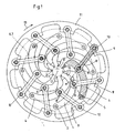
- the pressing tool shown in the drawing for pressing a tampon has a total of eight equally trained individual tools, which are arranged distributed uniformly over the circumference of a tampon blank 1 to be pressed. This number can also differ from eight.
- the press jaws 2 with the press cutters 3 can be moved in a substantially radial pivoting movement on the tampon blank 1 to press this by primarily radial forces and in this case to produce a so-called preform.
- the formed on the cheek plates 2 Preßste 3 in this case lead to the formation of longitudinal grooves in the tampon.
- the preform is composed of a central tampon core and radially outwardly extending from the tampon core longitudinal ribs, wherein the longitudinal ribs are separated from each other by the longitudinal grooves produced by the Preßchron 3.
- Each of the cheek plates 2 is attached to the free end of a pressing lever 4 and is aligned substantially perpendicular to the pressing lever 4. This attachment may be in one piece, alternatively, the individual cheek plates can be 2 also replaceable fasten at the end of the pressing lever 4 so as to exchange the cheek plates against other cheek plates can.
- the preferably curved designed pressing lever 4 are mounted at its other end on a hinge axis forming a bearing 5.
- the bearing shafts 5 all pressing lever 4 are located on a fixed support ring 6 or other stationary component of the tampon press.
- all bearing shafts 5 are fixed on a common, imaginary circle 7, so that the position of all bearing shafts 5 of the pressing lever is mutually immutable.
- FIG. 1 For clarification is in FIG. 1 one of the eight pressing lever 4 highlighted by a corresponding hatching.
- the pressing lever 4 are provided with pivot pin 8 attached thereto, via which the pressing lever are pivotally connected to pressure bars 9.
- a respective pressure rod 9 Preferably, on each side of the pressing lever 4 is a respective pressure rod 9, so as to allow a lateral force-free force introduction of the pressure rods 9 on the pressing lever.
- the pivot 8 forms a joint which, like FIG. 1 can recognize closer to the cheek plate 2 because of the bearing axis 5 of the pressing lever 4 sits.
- the hinge formed by the pivot 8 is located approximately in the second third of the length of the bent pressing lever 4, viewed from the bearing axis 5 thereof.
- the other end of the push rod 9 is articulated and that at a pivot pin 10 of an annular drive element 11.
- On the annular drive element 11 are distributed in a corresponding manner, evenly distributed over the circumference, and the pivot pin 10 for all other pressure rods 9.
- the annular drive element 11 is mounted about an axis of rotation 12, which coincides with the central axis of the tampon 1, so that the tampon press described is constructed entirely symmetrical overall.
- the annular drive element 11 moves concentrically not only to the tampon 1, but also to the circle 7, on which the fixed bearing shafts 5 are arranged for the pressing lever 4.
- FIG. 1 shows the tampon press in the open state and thus in the state in which the tampon blank 1 is inserted axially into the cylindrical space formed by the open cheek plates.
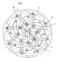
- FIG. 2 shows a contrast already more closed position of the cheek plates to exercise a holding function on the tampon blank.
- FIG. 3 shows the tampon press in the state of maximum pressing travel and thus also the maximum pressing pressure within the tampon. The cheek plates 2 are closed as far as possible.
- the formed preform can be ejected axially by means of a plunger from the mold cavity formed by the cheek plates.
- Stepwise movement of the tampon press is exclusively by turning the annular drive element 11 in the direction of the in FIGS. 1 and 2 drawn arrow 13 generates.
- the arrow 14 in FIG. 4 symbolizes the opening movement of the annular drive element 11 for the purpose of ventilating the tampon press.
- the preform in the released position according to FIG. 4 can the preform by means of the plunger eject axially and introduce it into a downstream mold in which it receives its final shape.
- This downstream mold is regularly formed as a conically tapered sleeve in which the preform is deformed to its final diameter.
- the angle ⁇ is drawn, which serves as the transmission element pressure rod 9 with respect to the imaginary connecting line 15 between the bearing axis 5 and cheek plate 2.
- this angle ⁇ is slightly greater than 90 °, in the positions after the Figures 3 and 4 slightly smaller than 90 °. This means that at least at a time of the pressing operation, the z. B. between the positions after the Figures 2 and 3 is to be settled, the direction R of the pressure rod 9 exerted on the pressing lever 4 force transmission substantially transversely, ie at right angles to the imaginary connecting line 15 between the bearing shaft 5 and cheek plate 2 takes place.
- the Preßhebels 4 therefore extends the power transmission direction R serving as a transmission element pressure rod 9 substantially transversely to this imaginary connecting line 15.
- the power transmission is optimal, ie it can be at moderate drive power for the annular drive element 11 very high compressive forces on the pressing lever 4 and thus generate the there perpendicularly arranged cheek plate 2.
- the direction R is almost directly aligned with the tampon 1.
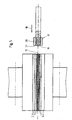
- FIG. 5 shows the entire press tool in a highly simplified longitudinal section, wherein axially in front of the pressing tool and in alignment of the axis of rotation 12, a plunger tool 17 is located.
- the plunger tool 17 is axially retractable in the direction provided with reference numeral 18 in the central mold space of the pressing tool 2 formed from the Preßbacken.
- the plunger tool 17 takes with the preform, and promotes this in a device downstream of the mold, in which it is z. B. may be a tapered towards its end sleeve, in which the preform receives its final shape.
- the front end face 19 of the plunger tool 17 which detects the preform has a star-shaped form, which will be described below with reference to FIGS FIGS. 6 and 7 is explained in more detail.
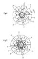
- FIG. 6 shows opposite FIG. 3 greatly increases the individual Preßbacken 2 with the Preßste 3 during the actual pressing operation, ie at maximum closed Preßbacken.
- the preform is very compacted in this state, which is why it would not be possible to eject the preform axially in this state from the fully closed cheek plates. For this reason, the pushing out occurs by means of the plunger tool in the also in FIG. 4 shown lifting position of the tampon press.
- This release position is also in FIG. 7 shown, and opposite FIG. 4 can be seen that the end face 19 is composed of a central, circular pressure surface 20 and radially extending therefrom additional pressure surfaces 21.
- the number of additional pressure surfaces 21 is equal to the number of Preßpac 3, also, When viewed in the axial direction, the additional pressure surfaces 21 are each placed on a gap 22 (FIG. Fig. 6 ) is aligned between two consecutive press cutters 3.
- the additional pressure surfaces 21 of the plunger tool 17 "fit" so exactly in these spaces 22 when the pad press has its released state.
- the defined by the outer edge 23 of the additional pressure surfaces 21 diameter D is greater than that by the inner edge 24 ( Fig. 6 ) of the Preßste 3 defined Preß trimmesser d, which applies both in relation to the Preß bemesser d with closed tampon press, as well as with respect to the Preß trimmesser d in the release position of the tampon press.
- the diameter D defined by the inner edge 24 of the press cutters 3 is greater than the minimum press diameter.
- the diameter of the central pressure surface 20 of the plunger is greater than that in FIG. 6 drawn minimum press diameter d of the press cutters 3.
- FIG. 6 is the width of the additional pressure surfaces 21 viewed in the circumferential direction is greater than the width of the gap 22 between two successive press cutting 3.
- FIG. 7 it would be the ram tool 17 impossible to retract into the mold cavity. This is true only when ventilated tampon press accordingly FIG. 7 possible.
- FIG. 7 are the additional pressure surfaces 21 designed to be extended to its outer edge 23 out. This leads to a further enlarged end face of the plunger tool and thus to a reduction of the pressure on the preform when pushing out and in particular in the initial overcoming the static friction between the tampon and press cutting.
Landscapes
- Health & Medical Sciences (AREA)
- Engineering & Computer Science (AREA)
- Vascular Medicine (AREA)
- Epidemiology (AREA)
- Biomedical Technology (AREA)
- Heart & Thoracic Surgery (AREA)
- Manufacturing & Machinery (AREA)
- Life Sciences & Earth Sciences (AREA)
- Animal Behavior & Ethology (AREA)
- General Health & Medical Sciences (AREA)
- Public Health (AREA)
- Veterinary Medicine (AREA)
- Absorbent Articles And Supports Therefor (AREA)
Claims (4)
- Dispositif destiné à la fabrication d'un tampon à partir d'une ébauche cylindrique en matériau absorbant ayant une forme de section quelconque, comportant un outil de pressage formé par plusieurs mâchoires de pressage (2), qui sont mobiles vers l'avant et l'arrière par rapport à l'ébauche (1) disposée au centre dudit outil de pressage et parmi lesquelles au moins une partie des mâchoires de pressage (2), réparties sur le pourtour de l'ébauche (1), sont munies d'arêtes de coupe (3) saillantes, destinées à réaliser des cannelures longitudinales dans l'ébauche pendant le processus de pressage, et comportant un outil poussoir (17) destiné à pousser la préforme comprimée hors de la presse dans la direction axiale, caractérisé en ce que la face frontale (19) active de l'outil poussoir (17) est formée par une surface de pression (20) centrale et des surfaces de pression supplémentaires (21) radialement en saillie sur cette dernière, en ce que le diamètre (D), défini par le bord extérieur (23) des surfaces de pression supplémentaires (21), est supérieur au diamètre de pressage (d) minimum, défini par le bord intérieur (24) des arêtes de coupe (3), et en ce que chaque surface de pression supplémentaire (21) est orientée axialement vers l'un des espaces intermédiaires (22) entre deux arêtes de coupe (3) consécutives.
- Dispositif selon la revendication 1, caractérisé en ce que les mâchoires de pressage (2) peuvent être réglées dans une position desserrée, dans laquelle le diamètre (D), défini par le bord intérieur (24) des arêtes de coupe (3), est supérieur au diamètre de pressage minimum de celles-ci, et en ce que le diamètre de la surface de pression (20) centrale de l'outil poussoir (17) est supérieur au diamètre de pressage minimum des arêtes de coupe (3).
- Dispositif selon la revendication 1 ou la revendication 2, caractérisé en ce que les mâchoires de pressage (2) peuvent être réglées dans une position desserrée, dans laquelle la distance circonférentielle entre deux arêtes de coupe (3) consécutives est supérieure à la distance circonférentielle (u) de celles-ci lorsque les mâchoires de pressage (2) sont fermées au maximum, et en ce que, lorsque les mâchoires de pressage (2) sont fermées au maximum, la largeur des surfaces de pression supplémentaires (21) dans la direction circonférentielle est supérieure à la distance circonférentielle (u) entre deux arêtes de coupe (3) consécutives.
- Dispositif selon l'une quelconque des revendications 1 à 3, caractérisé en ce que les surfaces de pression supplémentaires (21) sont conçues en s'élargissant vers l'extérieur.
Applications Claiming Priority (2)
| Application Number | Priority Date | Filing Date | Title |
|---|---|---|---|
| DE10151756A DE10151756C1 (de) | 2001-10-19 | 2001-10-19 | Vorrichtung zum Herstellen eines Tampons |
| DE10151756 | 2001-10-19 |
Publications (3)
| Publication Number | Publication Date |
|---|---|
| EP1304094A2 EP1304094A2 (fr) | 2003-04-23 |
| EP1304094A3 EP1304094A3 (fr) | 2003-12-17 |
| EP1304094B1 true EP1304094B1 (fr) | 2011-03-30 |
Family
ID=7703110
Family Applications (1)
| Application Number | Title | Priority Date | Filing Date |
|---|---|---|---|
| EP02022404A Expired - Lifetime EP1304094B1 (fr) | 2001-10-19 | 2002-10-04 | Appariel de fabrication d'un tampon |
Country Status (4)
| Country | Link |
|---|---|
| EP (1) | EP1304094B1 (fr) |
| AT (1) | ATE503447T1 (fr) |
| DE (2) | DE10151756C1 (fr) |
| ES (1) | ES2361731T3 (fr) |
Cited By (3)
| Publication number | Priority date | Publication date | Assignee | Title |
|---|---|---|---|---|
| US9072628B2 (en) | 2012-09-28 | 2015-07-07 | Kimberly-Clark Worldwide, Inc. | Shutter press compressor |
| US9072629B2 (en) | 2012-09-28 | 2015-07-07 | Kimberly-Clark Worldwide, Inc. | Shutter press compressor with movable jaws |
| US9078787B2 (en) | 2012-09-28 | 2015-07-14 | Kimberly-Clark Worldwide, Inc. | Shutter press compressor with shaping elements |
Families Citing this family (6)
| Publication number | Priority date | Publication date | Assignee | Title |
|---|---|---|---|---|
| CN109481151B (zh) * | 2018-12-18 | 2023-07-18 | 孙震 | 一种医用吸液棉生产装置及医用吸液棉生产系统 |
| US12533268B2 (en) | 2019-03-01 | 2026-01-27 | Tampro Inc. | Reduced-leakage tampon |
| USD977632S1 (en) | 2020-02-26 | 2023-02-07 | Tampro Inc. | Tampon |
| US12427069B2 (en) | 2020-09-01 | 2025-09-30 | Tampro Inc. | Reduced-leakage tampon |
| USD1039690S1 (en) | 2020-09-01 | 2024-08-20 | Tampro Inc. | Tampon |
| USD1046123S1 (en) | 2023-04-28 | 2024-10-08 | Tampro Inc. | Tampon |
Family Cites Families (5)
| Publication number | Priority date | Publication date | Assignee | Title |
|---|---|---|---|---|
| BE475102A (fr) * | 1942-06-02 | |||
| CH613114A5 (en) * | 1977-03-04 | 1979-09-14 | Baumgartner Papiers Sa | Method for manufacturing a cellulose or cotton pad and pad obtained by this method |
| DE4304505C2 (de) * | 1993-02-15 | 1995-05-18 | Johnson & Johnson Gmbh | Tampon, insbesondere für die Frauenhygiene, sowie Verfahren und Vorrichtung zur Herstellung desselben |
| DE9320358U1 (de) * | 1993-04-10 | 1994-07-21 | Karl Ruggli AG, Fisibach | Vorrichtung zur Herstellung von Tampons |
| DE19902643C1 (de) * | 1999-01-23 | 2000-03-09 | Ruggli Projects Ag | Vorrichtung zum Pressen eines Tampons, insbesondere für die Frauenhygiene |
-
2001
- 2001-10-19 DE DE10151756A patent/DE10151756C1/de not_active Expired - Fee Related
-
2002
- 2002-10-04 ES ES02022404T patent/ES2361731T3/es not_active Expired - Lifetime
- 2002-10-04 AT AT02022404T patent/ATE503447T1/de active
- 2002-10-04 DE DE50214983T patent/DE50214983D1/de not_active Expired - Lifetime
- 2002-10-04 EP EP02022404A patent/EP1304094B1/fr not_active Expired - Lifetime
Cited By (3)
| Publication number | Priority date | Publication date | Assignee | Title |
|---|---|---|---|---|
| US9072628B2 (en) | 2012-09-28 | 2015-07-07 | Kimberly-Clark Worldwide, Inc. | Shutter press compressor |
| US9072629B2 (en) | 2012-09-28 | 2015-07-07 | Kimberly-Clark Worldwide, Inc. | Shutter press compressor with movable jaws |
| US9078787B2 (en) | 2012-09-28 | 2015-07-14 | Kimberly-Clark Worldwide, Inc. | Shutter press compressor with shaping elements |
Also Published As
| Publication number | Publication date |
|---|---|
| DE50214983D1 (de) | 2011-05-12 |
| ES2361731T3 (es) | 2011-06-21 |
| EP1304094A2 (fr) | 2003-04-23 |
| DE10151756C1 (de) | 2003-03-06 |
| ATE503447T1 (de) | 2011-04-15 |
| EP1304094A3 (fr) | 2003-12-17 |
Similar Documents
| Publication | Publication Date | Title |
|---|---|---|
| DE69623567T2 (de) | Verfahren und Vorrichtung zur Herstellung von Pulverpresslingen | |
| WO1995003766A2 (fr) | Tampon et procede et dispositif pour sa fabrication | |
| EP2448538B1 (fr) | Procede de mise en forme finale d'un tampon | |
| EP2641673B1 (fr) | Procédé et dispositif de fabrication d'une section de raccordement comme élément d'un outil | |
| DE3049581C2 (de) | Vorrichtung zum Herstellen von mit einem Rückholband versehenen Tampons für die Frauenhygiene | |
| DE19911500B4 (de) | Schmiedeeinrichtung für ballige Schrägverzahnungen | |
| DE102011114504A1 (de) | Verfahren und Vorrichtung zur Herstellung eines Gangrads mit Kurzverzahnung | |
| EP1017518A1 (fr) | Dispositif de fluotournage et procede pour la fabrication d'engrenages a deux dentures interieures | |
| DE10151756C1 (de) | Vorrichtung zum Herstellen eines Tampons | |
| EP3305434B1 (fr) | Cassette conçue pour recevoir un ensemble de rouleaux profilés ou un ensemble de pièces formées par compression destinés à la formation de supports de lamelles ou analogues et outil de formation correspondant | |
| EP1171260B1 (fr) | Dispositif pour la division par rupture d'une piece | |
| EP1304095B1 (fr) | Procédé et appareil de fabrication d'un tampon | |
| DE2928707C2 (de) | Vorrichtung zum Herstellen von Gabelelementen | |
| DE19902643C1 (de) | Vorrichtung zum Pressen eines Tampons, insbesondere für die Frauenhygiene | |
| DE69218139T2 (de) | Vakuumstrangpresse für Metall | |
| EP0499064A1 (fr) | Machine pour ramasser et presser des produits agricoles récoltés | |
| DE2519416C3 (de) | Honwerkzeug für Bohrungen | |
| DE102019002187B4 (de) | Verfahren und Vorrichtung zum Herstellen eines Bauteils mit Gewinde | |
| EP1250199B1 (fr) | Procede et outil de deformation pour la fabrication de tubes cylindriques par formage par fluage | |
| AT392755B (de) | Hydraulische presse | |
| EP0888873A1 (fr) | Presse pour briquettes | |
| DE19946508C2 (de) | Verfahren zum Herstellen einer Welle mit durchmessergrößerem Flansch | |
| DE102012212717A1 (de) | Rollbiegeverfahren und -vorrichtung | |
| DE2644680C3 (de) | Einrichtung an einer Presse für die Verformung zylindrischer Rohlinge | |
| DE427004C (de) | Verfahren und Einrichtung zur Befestigung der Isolatorkappe in der Rille des Isolators |
Legal Events
| Date | Code | Title | Description |
|---|---|---|---|
| PUAI | Public reference made under article 153(3) epc to a published international application that has entered the european phase |
Free format text: ORIGINAL CODE: 0009012 |
|
| AK | Designated contracting states |
Designated state(s): AT BE BG CH CY CZ DE DK EE ES FI FR GB GR IE IT LI LU MC NL PT SE SK TR |
|
| AX | Request for extension of the european patent |
Extension state: AL LT LV MK RO SI |
|
| PUAL | Search report despatched |
Free format text: ORIGINAL CODE: 0009013 |
|
| AK | Designated contracting states |
Kind code of ref document: A3 Designated state(s): AT BE BG CH CY CZ DE DK EE ES FI FR GB GR IE IT LI LU MC NL PT SE SK TR |
|
| AX | Request for extension of the european patent |
Extension state: AL LT LV MK RO SI |
|
| 17P | Request for examination filed |
Effective date: 20040221 |
|
| AKX | Designation fees paid |
Designated state(s): AT BE BG CH CY CZ DE DK EE ES FI FR GB GR IE IT LI LU MC NL PT SE SK TR |
|
| 17Q | First examination report despatched |
Effective date: 20081118 |
|
| GRAP | Despatch of communication of intention to grant a patent |
Free format text: ORIGINAL CODE: EPIDOSNIGR1 |
|
| GRAS | Grant fee paid |
Free format text: ORIGINAL CODE: EPIDOSNIGR3 |
|
| GRAA | (expected) grant |
Free format text: ORIGINAL CODE: 0009210 |
|
| AK | Designated contracting states |
Kind code of ref document: B1 Designated state(s): AT BE BG CH CY CZ DE DK EE ES FI FR GB GR IE IT LI LU MC NL PT SE SK TR |
|
| REG | Reference to a national code |
Ref country code: GB Ref legal event code: FG4D Free format text: NOT ENGLISH |
|
| REG | Reference to a national code |
Ref country code: CH Ref legal event code: EP |
|
| REG | Reference to a national code |
Ref country code: CH Ref legal event code: NV Representative=s name: ABP PATENT NETWORK SWISS GMBH |
|
| REG | Reference to a national code |
Ref country code: IE Ref legal event code: FG4D |
|
| REF | Corresponds to: |
Ref document number: 50214983 Country of ref document: DE Date of ref document: 20110512 Kind code of ref document: P |
|
| REG | Reference to a national code |
Ref country code: DE Ref legal event code: R096 Ref document number: 50214983 Country of ref document: DE Effective date: 20110512 |
|
| RAP2 | Party data changed (patent owner data changed or rights of a patent transferred) |
Owner name: RUGGLI PROJECTS AG |
|
| REG | Reference to a national code |
Ref country code: ES Ref legal event code: FG2A Ref document number: 2361731 Country of ref document: ES Kind code of ref document: T3 Effective date: 20110621 |
|
| REG | Reference to a national code |
Ref country code: NL Ref legal event code: VDEP Effective date: 20110330 |
|
| PG25 | Lapsed in a contracting state [announced via postgrant information from national office to epo] |
Ref country code: GR Free format text: LAPSE BECAUSE OF FAILURE TO SUBMIT A TRANSLATION OF THE DESCRIPTION OR TO PAY THE FEE WITHIN THE PRESCRIBED TIME-LIMIT Effective date: 20110701 Ref country code: SE Free format text: LAPSE BECAUSE OF FAILURE TO SUBMIT A TRANSLATION OF THE DESCRIPTION OR TO PAY THE FEE WITHIN THE PRESCRIBED TIME-LIMIT Effective date: 20110330 |
|
| PG25 | Lapsed in a contracting state [announced via postgrant information from national office to epo] |
Ref country code: FI Free format text: LAPSE BECAUSE OF FAILURE TO SUBMIT A TRANSLATION OF THE DESCRIPTION OR TO PAY THE FEE WITHIN THE PRESCRIBED TIME-LIMIT Effective date: 20110330 Ref country code: CY Free format text: LAPSE BECAUSE OF FAILURE TO SUBMIT A TRANSLATION OF THE DESCRIPTION OR TO PAY THE FEE WITHIN THE PRESCRIBED TIME-LIMIT Effective date: 20110330 |
|
| REG | Reference to a national code |
Ref country code: IE Ref legal event code: FD4D |
|
| PG25 | Lapsed in a contracting state [announced via postgrant information from national office to epo] |
Ref country code: PT Free format text: LAPSE BECAUSE OF FAILURE TO SUBMIT A TRANSLATION OF THE DESCRIPTION OR TO PAY THE FEE WITHIN THE PRESCRIBED TIME-LIMIT Effective date: 20110801 Ref country code: EE Free format text: LAPSE BECAUSE OF FAILURE TO SUBMIT A TRANSLATION OF THE DESCRIPTION OR TO PAY THE FEE WITHIN THE PRESCRIBED TIME-LIMIT Effective date: 20110330 |
|
| PG25 | Lapsed in a contracting state [announced via postgrant information from national office to epo] |
Ref country code: SK Free format text: LAPSE BECAUSE OF FAILURE TO SUBMIT A TRANSLATION OF THE DESCRIPTION OR TO PAY THE FEE WITHIN THE PRESCRIBED TIME-LIMIT Effective date: 20110330 |
|
| PG25 | Lapsed in a contracting state [announced via postgrant information from national office to epo] |
Ref country code: NL Free format text: LAPSE BECAUSE OF FAILURE TO SUBMIT A TRANSLATION OF THE DESCRIPTION OR TO PAY THE FEE WITHIN THE PRESCRIBED TIME-LIMIT Effective date: 20110330 |
|
| PG25 | Lapsed in a contracting state [announced via postgrant information from national office to epo] |
Ref country code: IE Free format text: LAPSE BECAUSE OF FAILURE TO SUBMIT A TRANSLATION OF THE DESCRIPTION OR TO PAY THE FEE WITHIN THE PRESCRIBED TIME-LIMIT Effective date: 20110330 |
|
| PLBE | No opposition filed within time limit |
Free format text: ORIGINAL CODE: 0009261 |
|
| STAA | Information on the status of an ep patent application or granted ep patent |
Free format text: STATUS: NO OPPOSITION FILED WITHIN TIME LIMIT |
|
| PG25 | Lapsed in a contracting state [announced via postgrant information from national office to epo] |
Ref country code: DK Free format text: LAPSE BECAUSE OF FAILURE TO SUBMIT A TRANSLATION OF THE DESCRIPTION OR TO PAY THE FEE WITHIN THE PRESCRIBED TIME-LIMIT Effective date: 20110330 |
|
| 26N | No opposition filed |
Effective date: 20120102 |
|
| REG | Reference to a national code |
Ref country code: DE Ref legal event code: R097 Ref document number: 50214983 Country of ref document: DE Effective date: 20120102 |
|
| BERE | Be: lapsed |
Owner name: RUGGLI PROJECTS A.G. Effective date: 20111031 |
|
| PG25 | Lapsed in a contracting state [announced via postgrant information from national office to epo] |
Ref country code: MC Free format text: LAPSE BECAUSE OF NON-PAYMENT OF DUE FEES Effective date: 20111031 Ref country code: IT Free format text: LAPSE BECAUSE OF FAILURE TO SUBMIT A TRANSLATION OF THE DESCRIPTION OR TO PAY THE FEE WITHIN THE PRESCRIBED TIME-LIMIT Effective date: 20110330 |
|
| PG25 | Lapsed in a contracting state [announced via postgrant information from national office to epo] |
Ref country code: BE Free format text: LAPSE BECAUSE OF NON-PAYMENT OF DUE FEES Effective date: 20111031 |
|
| PGFP | Annual fee paid to national office [announced via postgrant information from national office to epo] |
Ref country code: GB Payment date: 20121023 Year of fee payment: 11 |
|
| PGFP | Annual fee paid to national office [announced via postgrant information from national office to epo] |
Ref country code: FR Payment date: 20130214 Year of fee payment: 11 |
|
| PG25 | Lapsed in a contracting state [announced via postgrant information from national office to epo] |
Ref country code: LU Free format text: LAPSE BECAUSE OF NON-PAYMENT OF DUE FEES Effective date: 20111004 |
|
| PG25 | Lapsed in a contracting state [announced via postgrant information from national office to epo] |
Ref country code: BG Free format text: LAPSE BECAUSE OF FAILURE TO SUBMIT A TRANSLATION OF THE DESCRIPTION OR TO PAY THE FEE WITHIN THE PRESCRIBED TIME-LIMIT Effective date: 20110630 |
|
| REG | Reference to a national code |
Ref country code: CH Ref legal event code: NV Representative=s name: ABP PATENT NETWORK AG, CH |
|
| PG25 | Lapsed in a contracting state [announced via postgrant information from national office to epo] |
Ref country code: TR Free format text: LAPSE BECAUSE OF FAILURE TO SUBMIT A TRANSLATION OF THE DESCRIPTION OR TO PAY THE FEE WITHIN THE PRESCRIBED TIME-LIMIT Effective date: 20110330 |
|
| GBPC | Gb: european patent ceased through non-payment of renewal fee |
Effective date: 20131004 |
|
| PG25 | Lapsed in a contracting state [announced via postgrant information from national office to epo] |
Ref country code: GB Free format text: LAPSE BECAUSE OF NON-PAYMENT OF DUE FEES Effective date: 20131004 |
|
| REG | Reference to a national code |
Ref country code: FR Ref legal event code: ST Effective date: 20140630 |
|
| PG25 | Lapsed in a contracting state [announced via postgrant information from national office to epo] |
Ref country code: FR Free format text: LAPSE BECAUSE OF NON-PAYMENT OF DUE FEES Effective date: 20131031 |
|
| PGFP | Annual fee paid to national office [announced via postgrant information from national office to epo] |
Ref country code: CZ Payment date: 20140930 Year of fee payment: 13 Ref country code: ES Payment date: 20141010 Year of fee payment: 13 Ref country code: DE Payment date: 20141023 Year of fee payment: 13 Ref country code: CH Payment date: 20141010 Year of fee payment: 13 |
|
| PGFP | Annual fee paid to national office [announced via postgrant information from national office to epo] |
Ref country code: AT Payment date: 20141022 Year of fee payment: 13 |
|
| PG25 | Lapsed in a contracting state [announced via postgrant information from national office to epo] |
Ref country code: CZ Free format text: LAPSE BECAUSE OF NON-PAYMENT OF DUE FEES Effective date: 20151004 |
|
| REG | Reference to a national code |
Ref country code: DE Ref legal event code: R119 Ref document number: 50214983 Country of ref document: DE |
|
| REG | Reference to a national code |
Ref country code: CH Ref legal event code: PL |
|
| REG | Reference to a national code |
Ref country code: AT Ref legal event code: MM01 Ref document number: 503447 Country of ref document: AT Kind code of ref document: T Effective date: 20151004 |
|
| PG25 | Lapsed in a contracting state [announced via postgrant information from national office to epo] |
Ref country code: DE Free format text: LAPSE BECAUSE OF NON-PAYMENT OF DUE FEES Effective date: 20160503 Ref country code: CH Free format text: LAPSE BECAUSE OF NON-PAYMENT OF DUE FEES Effective date: 20151031 Ref country code: LI Free format text: LAPSE BECAUSE OF NON-PAYMENT OF DUE FEES Effective date: 20151031 |
|
| PG25 | Lapsed in a contracting state [announced via postgrant information from national office to epo] |
Ref country code: AT Free format text: LAPSE BECAUSE OF NON-PAYMENT OF DUE FEES Effective date: 20151004 |
|
| REG | Reference to a national code |
Ref country code: ES Ref legal event code: FD2A Effective date: 20161125 |
|
| PG25 | Lapsed in a contracting state [announced via postgrant information from national office to epo] |
Ref country code: ES Free format text: LAPSE BECAUSE OF NON-PAYMENT OF DUE FEES Effective date: 20151005 |