EP1304182B1 - Procédé et utilisation d'un dispositif pour la formation d' une rainure dans une couche de friction - Google Patents
Procédé et utilisation d'un dispositif pour la formation d' une rainure dans une couche de friction Download PDFInfo
- Publication number
- EP1304182B1 EP1304182B1 EP01124913A EP01124913A EP1304182B1 EP 1304182 B1 EP1304182 B1 EP 1304182B1 EP 01124913 A EP01124913 A EP 01124913A EP 01124913 A EP01124913 A EP 01124913A EP 1304182 B1 EP1304182 B1 EP 1304182B1
- Authority
- EP
- European Patent Office
- Prior art keywords
- disk
- use according
- groove
- roller
- grooves
- Prior art date
- Legal status (The legal status is an assumption and is not a legal conclusion. Google has not performed a legal analysis and makes no representation as to the accuracy of the status listed.)
- Expired - Lifetime
Links
Images


Classifications
-
- B—PERFORMING OPERATIONS; TRANSPORTING
- B21—MECHANICAL METAL-WORKING WITHOUT ESSENTIALLY REMOVING MATERIAL; PUNCHING METAL
- B21H—MAKING PARTICULAR METAL OBJECTS BY ROLLING, e.g. SCREWS, WHEELS, RINGS, BARRELS, BALLS
- B21H7/00—Making articles not provided for in the preceding groups, e.g. agricultural tools, dinner forks, knives, spoons
- B21H7/18—Making articles not provided for in the preceding groups, e.g. agricultural tools, dinner forks, knives, spoons grooved pins; Rolling grooves, e.g. oil grooves, in articles
-
- F—MECHANICAL ENGINEERING; LIGHTING; HEATING; WEAPONS; BLASTING
- F16—ENGINEERING ELEMENTS AND UNITS; GENERAL MEASURES FOR PRODUCING AND MAINTAINING EFFECTIVE FUNCTIONING OF MACHINES OR INSTALLATIONS; THERMAL INSULATION IN GENERAL
- F16D—COUPLINGS FOR TRANSMITTING ROTATION; CLUTCHES; BRAKES
- F16D13/00—Friction clutches
- F16D13/58—Details
- F16D13/60—Clutching elements
- F16D13/64—Clutch-plates; Clutch-lamellae
-
- F—MECHANICAL ENGINEERING; LIGHTING; HEATING; WEAPONS; BLASTING
- F16—ENGINEERING ELEMENTS AND UNITS; GENERAL MEASURES FOR PRODUCING AND MAINTAINING EFFECTIVE FUNCTIONING OF MACHINES OR INSTALLATIONS; THERMAL INSULATION IN GENERAL
- F16D—COUPLINGS FOR TRANSMITTING ROTATION; CLUTCHES; BRAKES
- F16D13/00—Friction clutches
- F16D13/58—Details
- F16D13/60—Clutching elements
- F16D13/64—Clutch-plates; Clutch-lamellae
- F16D13/648—Clutch-plates; Clutch-lamellae for clutches with multiple lamellae
-
- F—MECHANICAL ENGINEERING; LIGHTING; HEATING; WEAPONS; BLASTING
- F16—ENGINEERING ELEMENTS AND UNITS; GENERAL MEASURES FOR PRODUCING AND MAINTAINING EFFECTIVE FUNCTIONING OF MACHINES OR INSTALLATIONS; THERMAL INSULATION IN GENERAL
- F16D—COUPLINGS FOR TRANSMITTING ROTATION; CLUTCHES; BRAKES
- F16D13/00—Friction clutches
- F16D13/58—Details
- F16D13/72—Features relating to cooling
-
- F—MECHANICAL ENGINEERING; LIGHTING; HEATING; WEAPONS; BLASTING
- F16—ENGINEERING ELEMENTS AND UNITS; GENERAL MEASURES FOR PRODUCING AND MAINTAINING EFFECTIVE FUNCTIONING OF MACHINES OR INSTALLATIONS; THERMAL INSULATION IN GENERAL
- F16D—COUPLINGS FOR TRANSMITTING ROTATION; CLUTCHES; BRAKES
- F16D69/00—Friction linings; Attachment thereof; Selection of coacting friction substances or surfaces
- F16D2069/004—Profiled friction surfaces, e.g. grooves, dimples
Definitions
- the invention concerns the use of a device for forming at least one groove in a friction layer of a covered plate for a force transmission aggregate, in particular for a clutch disk according to Claim 1, as well as a process for forming at least one groove in a friction layer of a friction plate for a force transmission aggregate, in particular for a clutch disk according to Claim 14.
- Disk clutches generally include a plurality of disks, which can be produced using the device described below or, as the case may be, using the process described below.
- a first group of disks of this type is provided upon a disk carrier fixed against rotation and sliding, and a second group is provided drivable upon a drive hub.
- the disks of the two groups intermesh or interdigitate in each other in the manner of gear teeth.
- the two groups are slideable relative to each other in the axial direction and thereby can be brought pair-wise into or out of engagement.
- a disk clutch of the above-described type is described, for example, in DE 199 06 980 A1 .
- the individual disks are preferably formed ring-shaped. Distinctions are made between so-called covered disks and so-called steel disks. Covered disks are in general constructed in sandwich-like manner.
- the base element for a ring-shaped covered disk of this type is a ring carrier, which is comprised for example of steel and is produced preferably by stamping.
- This sheet metal carrier carries a friction layer on one or both of its ring surfaces. This layer is comprised in general of a fibrous material, such as paper, or is produced from a paper-like material.
- disk clutches or disk brakes in which the disk is continuous, that is, is produced as a unitary piece of a friction material.
- a lubricant preferably oil
- the above-mentioned layer exhibits a sponge-like structure.
- the non-pressured condition that is, when there is no contact between adjacent disks, a certain amount of oil storage is taking place, which is again given off or released during actuation and the compression occurring in conjunction therewith.
- the grooves can be designed or formed in the most diverse design and manner. Depending upon the function to be fulfilled, these grooves can be in the form of rays, lines, curves, criss-cross and the like. Further, the most diverse groove cross-sectional shapes and sizes can be utilized.
- a material removing process step of this type has been found to be disadvantageous in many respects.
- a continuous manufacturing process is thus not possible.
- this type of material removing process exhibits the disadvantage, that the removed material disperses and soils the disk pre-form or the machine or machine parts.
- JP-A-63-084740 discloses a device for rolling grooves into a strip steel plate. The steel strip is then punched and formed into a clutch plate. JP-A-63-08474 represents the closest prior art.
- US-A-4 385 429 discloses in col. 3, lines 22 to 24 that a knurling tool which is rolled over the disc surface in one direction. This knurling tool indents the metal of the disk and forms one set of grooves.
- US-A-3073424 Discloses in col. 5, lines 48 to 49 the rolling of groove patterns into a disk by a suitable configured roller.
- the document refers to discs made of steel metal, only (col. 4, lines 34 and 45; col. 6, line 6).
- the invention is concerned with the task of providing a process for introduction of grooves into a friction layer comprised of a fibrous material or produced from a from a paper -like material of a covered disk, with which, or as the case may be, in which the above described problems no longer occur.
- a continuous manufacturing process should be made possible with high speed.
- the transfer as well as the manipulation of work pieces should occur in simple manner, and contamination should be substantially eliminated.
- a cost reduction is achieved.
- the task is inventively solved by a process for introduction of at least one groove in a friction layer of a friction disk or a force transmission aggregate, in particular for a disk clutch, with the features of the characterizing portion of Claim 14.
- the task is furthermore inventively solved by the use of a device according to claim 1.
- the inventive process is based on the idea, that the at least one groove is introduced by a rolling process.
- the device to be used includes a rolling device with at least one rolling arm for rolling the at least one groove.
- the disk is moved under the corresponding rolling device or the rolling device is moved over the disk.
- a process of this type can be integrated in simple manner into a continuous manufacturing process.
- the invention in particular envisions that the one or more grooves are introduced immediately subsequent to the process of gluing or lamination of the friction layer to the carrier material. It has further been found that a process of this type is suitable both for the introduction of grooves into a disk provided on one side with a friction layer, as well as for introduction into disks provided on both sides with a frictional layer.
- the rolling device includes a drive shaft rotatable about a rotation axis, co-axially upon which is provided at least one essentially circular shaped template disk, the disk defined by an outer diameter and an outer circumference or outer contour.
- the at least one rolling arm is thus formed by the outer circumference of the at least one circular shaped template disk.
- template disks provided side-by-side or adjacent to each other are spaced apart with the aid of appropriate spacer rings of, in certain cases, varying thicknesses.
- a device of this type is simple in design and manufacture, and therewith is economical. Further, the template disks as well as the spacer rings are easily manufactured and therewith also economical.
- grooves in a friction layer which preferably extend essentially linearly.
- the manufacture of curved grooves is only possible to a limited extent when using this device, since the circumference of the template disks must exhibit a corresponding curvature.
- groove designs can be produced in simple manner with crisscrossing grooves formed of essentially linearly groove tracks, in which the respective disk passes multiple times through the rolling process, however relative to the preceding process step is rotated by a certain angular amount with respect to the rolling device.
- the rolling device includes a drum rotatable about a rotation axis with an outer circumference surface, upon which again one rolling flange or multiple rolling flanges are provided. Since a drum of this type, in contrast to the above-described rolling disk, extends in the axial direction, rolling flanges can be provided and arranged in any type and manner. In particular, rolling flanges are possible which extend only partially in the axial direction, or which extend in any other mode and manner, even extending slanted or even curved.
- the outer circumference surface is formed as a cylinder.
- the introduction of the grooves corresponds then substantially to the above described embodiment. It is however essentially also possible, that the outer circumference surface is formed by the side surfaces of a cylinder with a multi-sided base shape.
- the corresponding rolling flange cross-sections are of various design.
- the corresponding cross sections can be of semicircular design, triangular design, trapezoidal design or a right-angled design, depending upon the cross-section of the groove to be produced. It is readily apparent that the cross sectional shape of the rolling flanges in both of the above described rolling devices can be varied.
- the invention envisions the provision of a heating device for heating the rolling flanges.
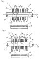
- the first illustrative embodiment of a rolling device 1, shown in Figure 1 is based upon a drive shaft 4 mounted rotatably about a rotation axis R (rotation direction ⁇ ). Seated upon this drive shaft 4 are arranged, co-axially, a total of seven template disk rings 2 .
- the individual template disk rings 2 are spaced apart via intermediate spacer rings 3 arranged co-axially in same manner.
- the total disk set is comprised of template disks 2 and spacer rings 3 which are essentially rigidly connected with the drive shaft 4 with the aid of - here not shown - fixing devices.
- a fixing device of this kind can be of a design for example such that the outer template disk 2 is screwed onto the drive shaft 4 .
- a rotation in the circumferential direction can be prevented for example thereby, that the template disk 2 and in certain cases also the spacer rings 3 have an internal teething and the drive shaft 4 exhibits an external teething, which engage in each other.
- the outer diameter d F of the template disks 2 is larger than the outer diameter d D of the spacer rings 3.
- the thickness a D of the spacer rings 3 provides the separation aN of the template disks 2 .
- the template disks 2 are curved arc-like at their outer circumference 8 . Since the outer circumference of the respective template disks 2 represent the respective rolling flanges 7 for rolling in of the groove, it can be seen that the groove to be introduced is to exhibit a semicircular bow-shaped cross sectional design.
- the rolling device 1 represented in Figure 1 is moved over the covered disk under a pre-tensioned force (pressure) or, as the case may be, in the converse the covered disk may be guided correspondingly under the rolling device 1 .
- a pre-tensioned force pressure
- the needed pre-tension amount depends upon the type and thickness of the friction layer as well as the type and the cross section of the groove to be introduced. Further care is to be taken that the friction layer is not already hardened or cured. It has been found particularly advantageous to carry out the rolling process immediately subsequent to the process of gluing or lamination of the friction layer with the carrier material.
- This cleaning device 5 can in the present case be designed as a brush device 6 .
- Rinsing or vacuum devices are likewise conceivable.
- the illustrative embodiment represented in Figure 2 shows a further development of the present described illustrative embodiment according to Figure 1 .
- the rolling device 11 is comprised, as in the above-described illustrative embodiment of a drive shaft 4 rotatable ( ⁇ ) about a rotation axis R with co-axially arranged circular-shaped template disks 2, 12 and spacer rings 3, 13 .
- the rolling flange cross section 17 has a semicircular arc shaped form at the circumference 18 of the respective template disks 2, 12 .
- a cleaning device 5 with brushes 6 is provided.
- the presently described illustrative embodiment differs with respect to the previously described example essentially thereby, that the spacer rings 3, 13 exhibit varying thicknesses.
- the corresponding dimensions or measurements are indicated in the drawing with the reference symbol a D1 or, as the case may be, a D2 .
- a further departure from the previously described example is comprised therein, that the diameters of the circular shaped template disks 2, 12 also differ.
- Four of the circular shaped template disks 2 exhibit a diameter d F1
- two template disks 12 exhibit diameter d F2 .
- This illustrative embodiment shows that, in a working step, grooves of different depths and with varying spacings to each other can be introduced into the friction layer.
- the rolling device 21 shown in Figure 3 is based, as in the above-described examples, upon a drive shaft 4 mounted rotatably ( ⁇ ) about a rotation axis R with a plurality of circular ring shaped template disks 22a, 22b, 22c, 22d, 22e and 22f, which again are spaced apart by means of appropriate spacer rings 3 , and seated co-axial upon the drive shaft 4 . From the representation according to Figure 3 one can further see rolling flanges with diverse designs of cross sections in the area of the outer circumference of the respective template disks 22a ... 22f.
- Two of the rolling flange cross sections exhibit, as in the above-described example, a semicircular arc shaped design 27c, two further exhibit a triangular shape 27a and 27b, two further exhibit trapezoid shaped design 27d, 27e and a last one exhibits a right-angled or squared-off design 27f .
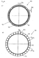
- Figure 4 illustrates, on the basis of representations of top views upon the friction disks with grooves, the types of groove patterns that can be produced with the aid of one or more of the previously described devices according to Figure 1 through 3 .
- Figure 4 a shows a groove image or pattern in which seven grooves are provided running linearly next to each other. Seven similarly arranged grooves 92 cross the above-described group of grooves 93 at an angle of about 90°. The separation of the respective grooves is indicated in the figure by the reference symbol aN.
- Figure 4 b shows a groove pattern in a friction layer 91 of a friction disk 90 in which three groups of grooves 93, 94 and 95 (individual grooves with spacing aN) are oriented concentrically, offset at an angle of 60° relative to each other.
- Figure 4 c) shows a so-called waffle groove pattern, in which two groups of grooves 92 and 93 (here the individual grooves of the respective groups) run crossing at right angles with a separation of a N1 or, as the case may be, a N2 .
- Figure 4 d shows a groove pattern changed slightly in comparison to the above groove designs, wherein the respective grooves of the corresponding grooves run at an angle of approximately 45° to each other. All groove patterns described previously and shown in Figure 4 can be produced in simple manner thereby, that a device for example as shown in Figure 1 is directed multiple times over the particular covered disk 90 , however in each subsequent step is respectively rotated about the corresponding above indicated angle.
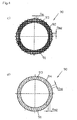
- FIG. 5 shows a further illustrative embodiment of an inventive rolling device 31 .
- This rolling device 31 according to Figure 5 is not formed as in the preceding described illustrative embodiments according to Figures 1 through 3 of disk sets with multiple template disks and spacing rings, but rather is comprised of a drum 32 rotatable about a rotation axis R (direction of rotation ⁇ ) with a cylindrical shaped circumference surface 38 .
- a drum 32 rotatable about a rotation axis R (direction of rotation ⁇ ) with a cylindrical shaped circumference surface 38 .
- Upon the circumference surface 38 of the drum 32 are provided, in the present example, three rolling flanges 37a, 37b and 37c which can run curved over the circumference in almost any desired manner.
- An illustrative embodiment of this type is suitable for introducing other, in particular also non-linear, groove paths or patterns in the friction layer 91 of a covered disk 90 .
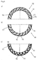
- Figure 6 a shows a friction layer with two groups of grooves.
- the grooves 96 of the first group run along secants, which thus cut into or across the ring shaped covered disk 90 .
- the other group of grooves includes two subgroups.
- the grooves 92 of the one subgroup run parallel to a radius of the ring shaped disk 90 , the grooves 93 of the other subgroup perpendicular thereto. In this manner there is produced a grid.
- the second group of grooves 92, 93 runs linearly, it is comparatively difficult to introduce these grooves with one of the devices according to Figures 1 through 3 .
- the device according to Figure 5 is however particularly suitable therefore.
- the groove image according to Figure 6 b) is formed similarly to the groove pattern according to Figure 6 a) .
- the groove pattern according to Figure 6 c) differs from this essentially thereby, that further bow-shaped grooves 98 are provided, which cut into or across the above-described bow-shaped grooves 97 .
- Both groove patterns according to Figure 6 b) and c) can be produced by a device according to Figure 5 .
Landscapes
- Engineering & Computer Science (AREA)
- General Engineering & Computer Science (AREA)
- Mechanical Engineering (AREA)
- Life Sciences & Earth Sciences (AREA)
- Agronomy & Crop Science (AREA)
- Mechanical Operated Clutches (AREA)
- Friction Gearing (AREA)
- Shaping Metal By Deep-Drawing, Or The Like (AREA)
Claims (15)
- Utilisation d'un dispositif de façonnage au rouleau (1, 11, 21, 31) doté d'au moins une bride de rouleau (7, 17, 27a ... 27f, 37a ... 37c) pour la formation au rouleau d'au moins une rainure (92, 93, 94, 95, 96, 97, 98) dans une couche de friction (91) en matériau fibreux ou produite à partir de matériau de type papier d'un disque recouvert d'une garniture (90) pour un agrégat servant à une transmission de force, en particulier pour un embrayage à disque.
- Utilisation selon la revendication 1, caractérisée en ce que le dispositif de façonnage au rouleau (1, 11, 21) comprend un arbre d'entraînement (4) tournant (ω) autour d'un axe de rotation (R), sur lequel au moins un disque de matriçage (2, 12, 22a ... 22f) est monté de manière coaxiale, et dont la circonférence extérieure (8, 18, 28) forme l'au moins une bride de rouleau (7, 17, 27a ... 27f).
- Utilisation selon la revendication 2, caractérisée en ce que plusieurs disques de matriçage (2, 12, 22a ... 22f) sont montés l'un à côté de l'autre sur l'arbre d'entraînement (4) avec une séparation axiale (aN, aN1, aN2).
- Utilisation selon la revendication 3, caractérisée en ce que des disques d'écartement (3, 13) sont montés entre les disques de matriçage (2, 12, 22a ... 22f).
- Utilisation selon une des revendications 2 à 4, caractérisée en ce que des disques de matriçage (2, 12, 22a ... 22f) ayant des diamètres différents (dF1, dF2) sont utilisés.
- Utilisation selon une des revendications 2 à 5, caractérisée en ce que des anneaux d'écartement (3, 13) ayant des épaisseurs différentes (aD1, aD2) sont utilisés.
- Utilisation selon la revendication 1, caractérisée en ce que le dispositif de façonnage au rouleau (31) est constitué d'un tambour (32) tournant (ω) autour d'un axe de rotation (R), et comportant une surface de circonférence (38) sur laquelle l'au moins une bride de rouleau (37a, 37b, 37c) est montée.
- Utilisation selon la revendication 1, caractérisée en ce que la surface de la circonférence (38) est cylindrique.
- Utilisation selon une des revendications 7 ou 8, caractérisée en ce qu'au moins une des brides de rouleau (37a, 37b, 37c) est orientée à un angle en pente ou incurvé par rapport à la direction axiale.
- Utilisation selon l'une des revendications précédentes, caractérisée en ce que des brides de rouleau (27a ... 27f) ayant des sections transversales de formes différentes sont utilisées.
- Utilisation selon l'une des revendications précédentes, caractérisée en ce que la section transversale du bord extérieur de la bride de rouleau a la forme d'un demi cercle (7, 17, 27c), d'un triangle (27a, 27b), d'un trapèze (27d, 27e) et/ou d'un angle droit (27f).
- Utilisation selon l'une des revendications précédentes, caractérisée en ce qu'un dispositif de chauffage est monté pour chauffer le dispositif de façonnage au rouleau (1, 11, 21, 31) ou les brides de rouleau (7, 17, 27a ... 27f, 37a ... 37c).
- Utilisation selon l'une des revendications précédentes, caractérisée en ce qu'un dispositif de nettoyage (5) est monté pour nettoyer le dispositif de façonnage au rouleau (1, 11, 21, 31) ou les brides de rouleau (7, 17, 27a ... 27f, 37a ... 37c).
- Procédé pour l'introduction d'au moins une rainure (92, 93, 94, 95, 96, 97, 98) dans une couche de friction (91) en matériau fibreux ou produite à partir de matériau de type papier d'un disque recouvert d'une garniture (90) pour un agrégat servant à une transmission de force, en particulier pour un embrayage à disque, caractérisé en ce que l'au moins une rainure (92, 93, 94, 96, 97, 98) est formée par un rouleau.
- Procédé selon la revendication 14, caractérisé en ce que l'au moins une rainure (92, 93, 94, 95, 96, 97, 98) est formée par un rouleau immédiatement après l'étape de collage de la couche de friction sur le matériau de support.
Priority Applications (5)
| Application Number | Priority Date | Filing Date | Title |
|---|---|---|---|
| EP01124913A EP1304182B1 (fr) | 2001-10-19 | 2001-10-19 | Procédé et utilisation d'un dispositif pour la formation d' une rainure dans une couche de friction |
| DE60133393T DE60133393T2 (de) | 2001-10-19 | 2001-10-19 | Verfahren und Verwendung einer Vorrichtung zur Herstellung einer Nut in einer Reibungsschicht |
| EP04009930A EP1464857A1 (fr) | 2001-10-19 | 2001-10-19 | Disque de friction avec une rainure dans sa couche de friction |
| KR1020020063659A KR20030035915A (ko) | 2001-10-19 | 2002-10-18 | 마찰층에 홈을 형성하기 위한 장치 |
| JP2002304143A JP2003194098A (ja) | 2001-10-19 | 2002-10-18 | 摩擦層に溝を形成するための装置 |
Applications Claiming Priority (1)
| Application Number | Priority Date | Filing Date | Title |
|---|---|---|---|
| EP01124913A EP1304182B1 (fr) | 2001-10-19 | 2001-10-19 | Procédé et utilisation d'un dispositif pour la formation d' une rainure dans une couche de friction |
Related Child Applications (1)
| Application Number | Title | Priority Date | Filing Date |
|---|---|---|---|
| EP04009930A Division EP1464857A1 (fr) | 2001-10-19 | 2001-10-19 | Disque de friction avec une rainure dans sa couche de friction |
Publications (2)
| Publication Number | Publication Date |
|---|---|
| EP1304182A1 EP1304182A1 (fr) | 2003-04-23 |
| EP1304182B1 true EP1304182B1 (fr) | 2008-03-26 |
Family
ID=8179008
Family Applications (2)
| Application Number | Title | Priority Date | Filing Date |
|---|---|---|---|
| EP01124913A Expired - Lifetime EP1304182B1 (fr) | 2001-10-19 | 2001-10-19 | Procédé et utilisation d'un dispositif pour la formation d' une rainure dans une couche de friction |
| EP04009930A Withdrawn EP1464857A1 (fr) | 2001-10-19 | 2001-10-19 | Disque de friction avec une rainure dans sa couche de friction |
Family Applications After (1)
| Application Number | Title | Priority Date | Filing Date |
|---|---|---|---|
| EP04009930A Withdrawn EP1464857A1 (fr) | 2001-10-19 | 2001-10-19 | Disque de friction avec une rainure dans sa couche de friction |
Country Status (4)
| Country | Link |
|---|---|
| EP (2) | EP1304182B1 (fr) |
| JP (1) | JP2003194098A (fr) |
| KR (1) | KR20030035915A (fr) |
| DE (1) | DE60133393T2 (fr) |
Cited By (1)
| Publication number | Priority date | Publication date | Assignee | Title |
|---|---|---|---|---|
| CN105107913A (zh) * | 2015-09-19 | 2015-12-02 | 青岛盛通机械科技有限公司 | 一种传动直联式自转模 |
Families Citing this family (6)
| Publication number | Priority date | Publication date | Assignee | Title |
|---|---|---|---|---|
| DE112007002505C5 (de) | 2006-11-06 | 2024-04-18 | Schaeffler Technologies AG & Co. KG | Kupplungsanordnung und Kraftübertragungseinrichtung mit einer Kupplungsanordnung |
| JP4894467B2 (ja) * | 2006-11-08 | 2012-03-14 | アイシン精機株式会社 | トルク変動吸収装置 |
| AT516209A1 (de) * | 2014-08-22 | 2016-03-15 | Miba Frictec Gmbh | Reibbaugruppe |
| AT516208A1 (de) | 2014-08-22 | 2016-03-15 | Miba Frictec Gmbh | Reibbaugruppe |
| US20170002873A1 (en) * | 2015-07-02 | 2017-01-05 | Deere & Company | Friction material groove pattern |
| DE102018131413A1 (de) * | 2018-04-05 | 2019-10-10 | Schaeffler Technologies AG & Co. KG | Reibteil |
Family Cites Families (13)
| Publication number | Priority date | Publication date | Assignee | Title |
|---|---|---|---|---|
| CH265584A (de) * | 1947-06-11 | 1949-12-15 | Trust Vadolt | Verfahren zur Erzielung einer schmiegsamen und nachgiebigen Oberflächenschicht an unnachgiebigen Körpern aus spanlos verformbarem Material, und nach dem Verfahren hergestellter Körper. |
| US2689493A (en) * | 1950-02-20 | 1954-09-21 | Emma G Bedker | Apparatus for rolling grooves |
| US3073424A (en) * | 1959-06-15 | 1963-01-15 | Eaton Mfg Co | Friction device |
| DE2007647A1 (de) * | 1970-02-19 | 1971-09-09 | Maschinenfabrik Augsburg Nürnberg AG, 8500 Nürnberg | Verfahren und Vorrichtung zum Her stellen von Ringnuten und/oder des Lauf flachenprofils am Dichtmantel eines Stahl kolbens von insbesondere Brennkraftma schinen |
| US4385429A (en) * | 1979-07-18 | 1983-05-31 | Dynetics, Inc. | Method of manufacturing a clutch plate |
| US4287978A (en) * | 1979-07-25 | 1981-09-08 | General Motors Corporation | Annular friction disc with radial grooving |
| DE2950349A1 (de) * | 1979-12-14 | 1981-06-19 | Daimler-Benz Ag, 7000 Stuttgart | Reibbelag fuer eine lamellen-kupplung oder -bremse |
| FR2490756B1 (fr) * | 1980-09-19 | 1986-03-14 | Renault | Embrayage multidisque equilibre |
| FR2523010A1 (fr) * | 1982-03-09 | 1983-09-16 | Stephanois Rech Mec | Procede de moletage coupant ou deformant, et des moyens de mise en oeuvre, destines a moleter ou rainurer des alesages ou portees cylindriques de pieces |
| US5101953A (en) * | 1986-09-16 | 1992-04-07 | Borg-Warner Automotive Transmission & Engine Components Corporation | High capacity viscous pumping groove pattern for a wet clutch |
| JPS6384740A (ja) * | 1986-09-27 | 1988-04-15 | Aichi Steel Works Ltd | 溝付きクラツチ板の製造方法およびそれに使用することができる装置 |
| DE4036908A1 (de) * | 1990-11-20 | 1992-05-21 | Ruetgers Pagid Ag | Nutausbildung |
| EP0810383B1 (fr) * | 1996-05-29 | 2003-03-19 | Dynax Corporation | Disque de friction |
-
2001
- 2001-10-19 EP EP01124913A patent/EP1304182B1/fr not_active Expired - Lifetime
- 2001-10-19 DE DE60133393T patent/DE60133393T2/de not_active Expired - Lifetime
- 2001-10-19 EP EP04009930A patent/EP1464857A1/fr not_active Withdrawn
-
2002
- 2002-10-18 KR KR1020020063659A patent/KR20030035915A/ko not_active Ceased
- 2002-10-18 JP JP2002304143A patent/JP2003194098A/ja active Pending
Cited By (1)
| Publication number | Priority date | Publication date | Assignee | Title |
|---|---|---|---|---|
| CN105107913A (zh) * | 2015-09-19 | 2015-12-02 | 青岛盛通机械科技有限公司 | 一种传动直联式自转模 |
Also Published As
| Publication number | Publication date |
|---|---|
| DE60133393D1 (de) | 2008-05-08 |
| EP1304182A1 (fr) | 2003-04-23 |
| KR20030035915A (ko) | 2003-05-09 |
| EP1464857A1 (fr) | 2004-10-06 |
| DE60133393T2 (de) | 2009-04-23 |
| JP2003194098A (ja) | 2003-07-09 |
Similar Documents
| Publication | Publication Date | Title |
|---|---|---|
| EP0625647B1 (fr) | Garniture de friction universelle à segments pour embrayage | |
| EP1876369B1 (fr) | Disques de frottement pour un couplage en milieu humide pour un véhicule | |
| EP0550961A1 (fr) | Matériau de garniture pour disque d'embrayage humide | |
| EP1304182A1 (fr) | Dispositif pour la formation d' une rainure dans une couche de friction | |
| CN109958724B (zh) | 摩擦离合器板的锐角边缘凹槽 | |
| CN102575723A (zh) | 同步环摞以及用于构成同步环的摩擦片衬里的方法 | |
| JP4568962B2 (ja) | クラッチのドラム及び内歯部材の成形装置 | |
| JP2009531616A (ja) | 調整板を有するギアボックス | |
| JP2009530567A (ja) | 軸受組立部品 | |
| JP5065966B2 (ja) | 円筒状クラッチ部品の成形方法 | |
| JP5506766B2 (ja) | 変速機の同期装置 | |
| US7197808B2 (en) | Process for forming a groove in a friction layer | |
| JP5428183B2 (ja) | 円筒状クラッチ部品の成形方法及び成形装置 | |
| DE102010054253B4 (de) | Nasslaufende Kraftfahrzeugreibkupplung | |
| US6948598B2 (en) | Brake drum for wet-type band brake drum and method for manufacturing the same | |
| JP2003056614A (ja) | 湿式摩擦部材 | |
| CN103133555B (zh) | 离合器本体以及用于制造离合器本体的方法 | |
| CN109715965B (zh) | 摩擦盘 | |
| JP5968332B2 (ja) | 表面形状を有するフレキシブルな金属リング、及び積層されたフレキシブルな金属リングセットを備える駆動ベルト | |
| JP3475556B2 (ja) | トロイダル型無段変速機 | |
| AT524999B1 (de) | Verfahren zur Herstellung einer Reiblamellenanordnung | |
| JP2006275089A (ja) | クラッチドラム及びその製造方法 | |
| JP2865587B2 (ja) | 歯付き伝動要素の製造方法 | |
| KR20200054079A (ko) | 디스크 클러치 또는 브레이크용 디스크, 이러한 디스크를 구비한 디스크 클러치 또는 브레이크, 및 이러한 디스크의 제조방법 | |
| DE102011120811A1 (de) | Reiblamellen, Lamellenkupplung und Verfahren zur Herstellung von Reiblamellen |
Legal Events
| Date | Code | Title | Description |
|---|---|---|---|
| PUAI | Public reference made under article 153(3) epc to a published international application that has entered the european phase |
Free format text: ORIGINAL CODE: 0009012 |
|
| AK | Designated contracting states |
Designated state(s): AT BE CH CY DE DK ES FI FR GB GR IE IT LI LU MC NL PT SE TR |
|
| AX | Request for extension of the european patent |
Extension state: AL LT LV MK RO SI |
|
| 17P | Request for examination filed |
Effective date: 20030627 |
|
| 17Q | First examination report despatched |
Effective date: 20030902 |
|
| AKX | Designation fees paid |
Designated state(s): DE FR |
|
| RAP1 | Party data changed (applicant data changed or rights of an application transferred) |
Owner name: BORGWARNER INC. |
|
| RIC1 | Information provided on ipc code assigned before grant |
Ipc: B21H 7/18 20060101AFI20070924BHEP Ipc: F16D 13/64 20060101ALN20070924BHEP |
|
| RTI1 | Title (correction) |
Free format text: METHOD AND USE OF A DEVICE FOR FORMING A GROOVE IN A FRICTION LAYER |
|
| GRAP | Despatch of communication of intention to grant a patent |
Free format text: ORIGINAL CODE: EPIDOSNIGR1 |
|
| GRAS | Grant fee paid |
Free format text: ORIGINAL CODE: EPIDOSNIGR3 |
|
| GRAA | (expected) grant |
Free format text: ORIGINAL CODE: 0009210 |
|
| AK | Designated contracting states |
Kind code of ref document: B1 Designated state(s): DE FR |
|
| REF | Corresponds to: |
Ref document number: 60133393 Country of ref document: DE Date of ref document: 20080508 Kind code of ref document: P |
|
| EN | Fr: translation not filed | ||
| PLBE | No opposition filed within time limit |
Free format text: ORIGINAL CODE: 0009261 |
|
| STAA | Information on the status of an ep patent application or granted ep patent |
Free format text: STATUS: NO OPPOSITION FILED WITHIN TIME LIMIT |
|
| 26N | No opposition filed |
Effective date: 20081230 |
|
| PG25 | Lapsed in a contracting state [announced via postgrant information from national office to epo] |
Ref country code: FR Free format text: LAPSE BECAUSE OF FAILURE TO SUBMIT A TRANSLATION OF THE DESCRIPTION OR TO PAY THE FEE WITHIN THE PRESCRIBED TIME-LIMIT Effective date: 20090116 |
|
| PGFP | Annual fee paid to national office [announced via postgrant information from national office to epo] |
Ref country code: DE Payment date: 20171027 Year of fee payment: 17 |
|
| REG | Reference to a national code |
Ref country code: DE Ref legal event code: R119 Ref document number: 60133393 Country of ref document: DE |
|
| PG25 | Lapsed in a contracting state [announced via postgrant information from national office to epo] |
Ref country code: DE Free format text: LAPSE BECAUSE OF NON-PAYMENT OF DUE FEES Effective date: 20190501 |