EP1304227A2 - Transportgerät für fixiertes Material und Flüssigkeitsfixiergerät mit einem solchen Transportgerät - Google Patents
Transportgerät für fixiertes Material und Flüssigkeitsfixiergerät mit einem solchen Transportgerät Download PDFInfo
- Publication number
- EP1304227A2 EP1304227A2 EP02023086A EP02023086A EP1304227A2 EP 1304227 A2 EP1304227 A2 EP 1304227A2 EP 02023086 A EP02023086 A EP 02023086A EP 02023086 A EP02023086 A EP 02023086A EP 1304227 A2 EP1304227 A2 EP 1304227A2
- Authority
- EP
- European Patent Office
- Prior art keywords
- fixed material
- recording
- suction
- sheet
- recess
- Prior art date
- Legal status (The legal status is an assumption and is not a legal conclusion. Google has not performed a legal analysis and makes no representation as to the accuracy of the status listed.)
- Granted
Links
- 239000000463 material Substances 0.000 title claims abstract description 76
- 239000007788 liquid Substances 0.000 title claims abstract description 15
- 230000032258 transport Effects 0.000 claims description 8
- 238000011144 upstream manufacturing Methods 0.000 claims description 4
- 230000000630 rising effect Effects 0.000 abstract description 2
- 230000006837 decompression Effects 0.000 description 19
- 230000003245 working effect Effects 0.000 description 17
- 238000010586 diagram Methods 0.000 description 13
- 238000007599 discharging Methods 0.000 description 12
- 238000004891 communication Methods 0.000 description 11
- 239000007787 solid Substances 0.000 description 5
- 230000000694 effects Effects 0.000 description 4
- 238000010521 absorption reaction Methods 0.000 description 2
- 238000003491 array Methods 0.000 description 2
- 230000000052 comparative effect Effects 0.000 description 2
- 238000005516 engineering process Methods 0.000 description 2
- 239000003595 mist Substances 0.000 description 2
- 238000005192 partition Methods 0.000 description 2
- 239000006096 absorbing agent Substances 0.000 description 1
- 238000001514 detection method Methods 0.000 description 1
- 230000006866 deterioration Effects 0.000 description 1
- 238000007667 floating Methods 0.000 description 1
- 238000012986 modification Methods 0.000 description 1
- 230000004048 modification Effects 0.000 description 1
- 238000007639 printing Methods 0.000 description 1
- 238000005549 size reduction Methods 0.000 description 1
- 230000003068 static effect Effects 0.000 description 1
Images





Classifications
-
- B—PERFORMING OPERATIONS; TRANSPORTING
- B41—PRINTING; LINING MACHINES; TYPEWRITERS; STAMPS
- B41J—TYPEWRITERS; SELECTIVE PRINTING MECHANISMS, i.e. MECHANISMS PRINTING OTHERWISE THAN FROM A FORME; CORRECTION OF TYPOGRAPHICAL ERRORS
- B41J11/00—Devices or arrangements of selective printing mechanisms, e.g. ink-jet printers or thermal printers, for supporting or handling copy material in sheet or web form
- B41J11/02—Platens
- B41J11/06—Flat page-size platens or smaller flat platens having a greater size than line-size platens
-
- B—PERFORMING OPERATIONS; TRANSPORTING
- B41—PRINTING; LINING MACHINES; TYPEWRITERS; STAMPS
- B41J—TYPEWRITERS; SELECTIVE PRINTING MECHANISMS, i.e. MECHANISMS PRINTING OTHERWISE THAN FROM A FORME; CORRECTION OF TYPOGRAPHICAL ERRORS
- B41J11/00—Devices or arrangements of selective printing mechanisms, e.g. ink-jet printers or thermal printers, for supporting or handling copy material in sheet or web form
- B41J11/0065—Means for printing without leaving a margin on at least one edge of the copy material, e.g. edge-to-edge printing
-
- B—PERFORMING OPERATIONS; TRANSPORTING
- B41—PRINTING; LINING MACHINES; TYPEWRITERS; STAMPS
- B41J—TYPEWRITERS; SELECTIVE PRINTING MECHANISMS, i.e. MECHANISMS PRINTING OTHERWISE THAN FROM A FORME; CORRECTION OF TYPOGRAPHICAL ERRORS
- B41J11/00—Devices or arrangements of selective printing mechanisms, e.g. ink-jet printers or thermal printers, for supporting or handling copy material in sheet or web form
- B41J11/0085—Using suction for maintaining printing material flat
Definitions
- the present invention relates to a fixed material transportation apparatus and a liquid fixing apparatus provided with the transportation apparatus, and particularly to technology for sucking and holding a fixed material in a fixing section of a liquid fixing apparatus.
- an ink jet printer that transports, a recording medium, which is a liquid fixing apparatus
- the recording medium absorbs a large quantity of ink and frequently expands in a wavy manner, that is, cockling is frequently caused.
- this cockling is caused, the recording medium rises up, and a gap (paper gap) between the recording medium and a recording head is reduced, so that the splash distance of the ink droplet becomes uneven thereby to cause unevenness in recording, or the recording medium comes into contact with the recording head thereby to be stained.
- an object of the invention is to prevent rising-up due to cockling of a fixed material in a liquid fixing apparatus and make setting of a proper paper gap possible thereby to make possible recording of high quality on the fixed material.
- a fixed material transportation apparatus comprises a suction unit that sucks and holds a fixed material on a fixed material transporting surface, and a fixed material transporting device that transports the fixed material on the fixed material transporting surface from the upstream side of the suction unit to the downstream side thereof, wherein plural recesses that are indented from surroundings are formed so as to be aligned in a main scanning direction on the fixed material transporting surface, an inner sucking hole is formed in the recess, and an outer sucking hole is formed between the recesses at least in the main scanning direction on the fixed material transporting surface.
- the fixed material By suction force of the suction unit, the fixed material is sucked and held from the fixed material transporting surface that is on the opposite side to a fixing surface.
- the fixed material is sucked by the outer sucking hole on the fixed material transporting surface, a bottom portion of cockling occurring in the fixed material falls into the recess on the fixed material transporting surface, and the recess is made in a closed space state by the sucking hole in the recess, whereby the fixed material is further sucked and sucked by its negative pressure.
- the recess is partitioned also in the sub-scanning direction thereby to become the closed space, and by raising airtightness between the fixed material and the recess, the fixed material is closely attached onto the fixed material transporting surface.
- the shape of the cockling occurring in the fixed material can be corrected into a shape according to the shape of the suction unit, so that rising-up of the fixing material due to the cockling occurring in the fixed material can be prevented more effectively. Therefore, the proper paper gap can be set, so that recording of high quality can be performed on the fixed material.
- the recess has slanted faces descending from the fixed material transporting surface toward the bottom of the recess, and its shape becomes the shape according to a curve of the cockling occurring in the fixed material at the ink absorption time. Therefore, the airtightness between the recess and the fixed material rises, so that effect in suction becomes high and the rising-up of the fixed material due to the cockling can be prevented more effectively.
- the fixed material transportation apparatus is characterized by having a sucking hole in the slanted face.
- the fixed material transportation apparatus is characterized in that the recess has, in the sub-scanning direction, at least one protrusion that is lower than the fixed material transporting surface.
- the protrusion does not obstruct transportation of the fixed material, the rising-up of the fixed material is prevented and further the large suction force is obtained.
- the fixed material transportation apparatus is characterized in that the recess of the fixed material transporting surface is composed of a recess curved surface.
- the shape of the recess fits to the shape of the cockling occurring in the fixed material, so that the airtightness between the recess and the fixed material becomes high. Therefore, the effect of suction becomes high.
- the fixed material transportation apparatus is characterized in that the sucking hole on the fixed material transporting surface is chamfered at least on its downstream side in the sub-scanning direction.
- the transportation of the fixed material is not obstructed.
- a liquid fixing apparatus is characterized by having a fixed material transportation apparatus. According to this liquid fixing apparatus, the working effect in any one of the first to sixth aspects can be obtained.
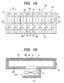
- Figs. 1A and 1B are diagrams showing the main constitution of a suction unit according to a first embodiment of the invention, in which Fig. 1A is its plan view and Fig. 1B is its sectional view.
- a suction unit 100 in this embodiment comprises a suction part 101 in an upper step and a suction force generating part 104 in a lower step, and it is formed in the shape of a hollow box.
- the suction part 101 as shown in Figs.
- FIG. 1A and 1B comprises a decompression chamber 102 formed inside, plural suction chambers 106 that are respectively formed in the shape of a approximately rectangular recess on a transporting surface 107 of a recording medium, and plural sucking holes 32 for communicating these suction chambers 106 respectively with the decompression chamber 102.
- a sucking hole 31 that corresponds to a sucking hole in the conventional suction structure and communicates the transporting surface for the recording medium and the decompression chamber 102 is formed between the recesses in the main scanning direction (in the direction D in Figs. 1A and 1B), that is, between the adjacent suction chambers 106.
- the suction force generating part 104 communicates with the decompression chamber 102 of the suction part 101 through a communication hole 111, and includes a pump 112 having a centrifugal fan. Further, also in the sub-scanning direction (in the direction E in Figs. 1A and 1B) on the transporting surface 107, the suction chambers 106, the sucking holes 32 and the sucking holes 31 can be formed similarly.
- the .sucking hole 32 is formed in the suction chamber 106 and it is consisted of a through hole having a small diameter.
- the lower portion of the cockling can be sucked by the suction chamber 106 and the sucking hole 32, and the upper portion thereof can be sucked and absorbed by the sucking hole 31, so that larger suction force can be obtained.
- the suction chamber 106 sucks the recording medium, whereby the recording medium is closely attached onto the transporting surface 107 surrounding the suction chamber 106, so that the suction chamber becomes a closed space, and negative pressure of its closed space gives the large suction force to the recording medium.
- the basic structure of a suction unit 100 according to another embodiment is approximately similar to that in the first embodiment. Therefore, parts similar to those in the first embodiment are denoted by the same reference numerals, and their detailed description is omitted.
- suction units 100 according to other embodiments will be described below while they are being compared with those according to the first embodiment and the conventional unit.
- Fig. 2 is a diagram showing a working effect of a previous suction unit 100 as a comparative example, which was developed before the foregoing embodiments of the present invention were accomplished
- Fig. 3 is a diagram showing a working effect of the suction unit according to the first embodiment
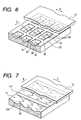
- Figs. 4 to 6 are diagrams showing working effects of suction units 100 according to second to fourth embodiments.
- ⁇ P is similar to those of the suction units according to the first and other embodiments. However, since the area of the surface of the sucking hole 31 opposed to the recording medium (sectional area) A1 is smallest, the suction force is small.
- the suction chamber 106 that is a recess indented from the surroundings is formed in the main scanning direction (in the direction E) between the adjacent sucking holes 31, and the sucking hole 32 is formed in the suction chamber 106. Further, the plural suction chambers 106, sucking holes 32, and sucking holes 31 are similarly arranged also in the sub-scanning direction (in the direction D).
- ⁇ P P0-P is similar to those of the conventional suction units 100 and suction units 100 according to other embodiments. However, since the area of the surface of the suction chamber 106 opposed to the recording medium 10 (sectional area) A2 is larger than that in the conventional case, the suction force is large.
- the recording medium 10 When the recording medium 10 is fed on the transporting surface 107, it is sucked firstly by the sucking holes 31 on the transporting surface 107. Next, since the recording medium 10 absorbing a large quantity of ink such as ink of solid image is sucked and absorbed by the sucking holes 31, the occurring cockling falls into the suction chambers 106. Into the suction chamber 106 that becomes in a state of the closed space because the recording medium 10 falls downward, the recording medium is further sucked strongly by its negative pressure. In result, the upper portion of the cockling does not rise up, and the shape of the cockling is corrected into a shape corresponding to the shape of the suction unit.
- sucking holes 31 and 32 may be approximately circular or approximately polygonal. Further, plural sucking holes 32 may be formed into the suction chamber 106.
- a partition wall 119 between suction chambers 106 formed on a flat formed transporting surface 107 continuously in the sub-scanning direction E is lower than the transporting surface 107.
- the partition wall 119 serves as a protrusion that is lower than the fixed material transporting surface 107.
- a suction chamber 106 that is a recess are formed slantingly and sucking holes 33 are formed in its slanted faces.
- a recording medium 10 absorbs a large quantity of ink such as ink of solid image, as shown in Fig. 6, the recording medium 10 located at the upper portion of the suction chamber 106 is sucked and absorbed similarly to in the first embodiment. Therefore, cockling is easy to fall down into the suction chambers 106.
- the sucking holes 33 formed on the slanted faces suck the cockling auxiliarily, and work so as to guide the bottom of the cockling to the sucking hole 32 located at the bottom of the suction chamber 106.
- the upper portion of the cockling does not rise up, and the shape of the cockling is corrected into a shape corresponding to the shape of the suction unit 100.
- suction chambers 106 that are recesses are formed on a transporting surface 107.
- its recess comprises a concave curved surface and is formed continuously.
- This recess has the approximately same shape as cockling occurring in a recording medium 10.
- Figs. 8A and 8B are diagrams showing the shape of a sucking hole 31 on a transporting surface 107, in which Fig. 8A is its plan view and Fig. 8B is its sectional view.
- an edge of an outer sucking hole 31 located outside the recess is chamfered on its downstream side in the sub-scanning direction E that is a transporting direction of a recording medium.
- the recording medium passes on the sucking hole 31 on the transporting surface 107, the recording medium is transported without being caught at its leading end.
- a sucking hole 32 inside a suction chamber 106 is also chamfered similarly, the similar working effect can be obtained.
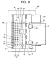
- Fig. 9 is a schematic plan view showing one embodiment of an ink jet printer that is a liquid fixing apparatus to which the invention is applied, and Fig. 10 is a side view thereof.
- a recording unit 14 comprising a recording head 18 and a suction unit 100 located below the recording head 18 by a recording medium transportation apparatus 50 that transports the recording sheet in the transporting direction D at the recording, and the recording sheet 10'on which data has been recorded is discharged to the outside of the printer body 200.
- a manual sheet feeding port 204 (refer to Fig. 10) not shown in Fig.
- a recording sheet 10' various paper can be used, for example, dedicated paper for ink jet printer, plain paper, an OHP film, tracing paper, a postcard, and the like.
- the recording medium transportation apparatus 50 includes the suction unit 100 that sucks and holds the recording sheet 10' at the recording, and a recording medium transporting device that transports the recording sheet 10' from the upstream side of the suction unit 100 to the downstream side thereof.
- the recording medium transporting device comprises a sheet supply roller 221 for picking up and feeding out the recording sheets 10' stored onto the sheet tray 212 one by one, a sheet feeding roller 12 and its driven roller 12a that feed the recording sheet 10' between the recording head 18 and the suction unit 100, and a sheet discharging roller and a spur roller 16a functioning as its driven roller that discharge the recording sheet 10' on which data has been recorded to the outside of the recording unit 14.
- an arrow L represents a transporting path of the recording sheet 10' transported by the recording medium transportation apparatus 50.
- the recording head 18 is mounted on a carriage 230 supported slidably by a guide shaft 51 provided in parallel in the direction D (main scanning direction) orthogonal to the transporting direction E (sheet feeding direction or sub-scanning direction) of the recording sheet 10'.
- This carriage 230 slides on the guide shaft 51-by a timing belt driven by a carriage drive motor 40.
- the recording head 18 has nozzle arrays comprising plural nozzles such as 96 nozzles for each color, and ink for each color supplied from an ink cartridge 233 detachably attached to the carriage 230 is ejected on the recording sheet 10' according to print data from all or part of the plural nozzles as a minute ink droplet.
- the suction unit 100 is arranged in a position opposed to the recording head 18 with the transporting path L of the recording sheet 10' between, comprises a suction part 101 in an upper step and a suction force generating part 104 in a lower step, and is formed in the shape of a hollow box.
- the suction part 101 as shown in Fig. 10, comprises a decompression chamber 102 formed inside, plural suction chambers 106 (sectional area S3) that are respectively formed in the shape of an approximately rectangular recess on a transporting surface 107 of the recording sheet 10', and plural sucking holes 32 (sectional area S1) arranged vertically so as to communicate these suction chambers 106 with the decompression chamber 102.
- the suction chamber 106 is formed so that the area S3 of the suction surface opposed to the recording sheet 10' is larger than the sectional area S1 of the sucking hole 32.
- the suction force generating part 104 communicates with the decompression chamber 102 of the suction part 101 through a communication hole 111, and includes a pump 112 having a centrifugal fan.
- the pump 112 is attached in the predetermined position below the decompression chamber 102 in a state where it communicates with the decompression chamber 102 through a communication hole 111, and the centrifugal fan is operated at the recording.
- the pump 112 of the suction unit 100 is always rotating, intake force by the pump 112 acts on the sucking hole 32, the suction chamber 106, and the sucking hole 31 through the communication hole 111 and the decompression chamber 102, so that they come to the intake and suction state.
- the sheet supply roller 221 of the ASF unit 202 is driven and rotated, and picks up and feeds out the recording sheets 10' stored onto the sheet tray 212 one by one. Further, the sheet feeding roller 12 is driven and rotated by driving force of a stepping motor, and transports the recording sheet 10' so as to feed it between the recording head 18 and the suction unit 100.
- the recording sheet 10' fed into the recording unit 14 is sucked and absorbed on a recording medium transporting surface 107 of the suction unit 100, and transported in a state where the recording sheet is closely attached to the transporting surface.
- the recording head 18 is moving above the recording sheet 10' in the main scanning direction (in the direction D), it ejects ink droplets onto the recording sheet 10' to perform image recording.
- the recording sheet 10' is fed out from the recording unit 14 by the discharging roller 16 and the spur roller 16a functioning as a driven roller or it is fed out from the recording unit 14 by the movement of the suction unit 100. Thereafter, the recording sheet 10' is discharged to the outside of the printer. At this time, as described above, since rising-up due to the cockling is not produced in the recording sheet 10, even if the spur roller 16a is used, spur traces are not given.
- the suction unit 100 is constituted movably in the discharging direction, whereby sheet discharge may be performed without providing the discharging roller 16 and the spur roller 16a in Figs. 9 and 10.
- Fig. 11 is a schematic plan view showing another embodiment of the recording medium transportation apparatus
- Fig. 12 is its side view. Further, parts similar to those previously described in the first embodiment of the ink jet printer as the recording apparatus are denoted by the same reference numerals and their description is omitted.
- a printer body 200 functioning as a recording medium transportation apparatus includes a movable suction/sheet discharging unit 1 functioning as a unit for discharging the recorded recording sheet 10'.
- the suction/sheet discharging unit 1 comprises a fixed table 21, a movable table 22, a pump 112 including a centrifugal fan as a decompression unit, and a release nozzle 20.
- the suction/sheet discharging unit 1 the recording sheet 10' is moved and discharged in the sub-scanning direction E.
- the fixed table 21 has a first decompression chamber 121 having a hollow structure, arranged in a state where it is fixed to the recording medium transportation apparatus 50 body, and has a pump 112 at its bottom.
- the pump 112 communicates with the first decompression chamber 121 through a first communicating hole 108.
- the pump 112 rotates, whereby air in the first decompression chamber 121 is sucked in the direction of an arrow H, and the inside of the first decompression chamber 121 is pressure-reduced.
- a second communication hole 109 communicating with the first decompression chamber 121 is formed on the upper surface of the fixed table 21, a second communication hole 109 communicating with the first decompression chamber 121 is formed.
- the movable table 22 has a second decompression chamber 122 having a hollow structure, and arranged so that it can slide on the fixed table 21 in the sub-scanning direction E. Further, at the bottom of the movable table 22, a third communication hole 110 communicating with the second decompression chamber 122 is formed. Further, on the upper surface of the movable table 22, in addition to a sucking hole 31 communicating with the second decompression chamber 122, a sucking hole 32 is formed in a suction chamber 106, and the sucking hole 32 consists of a through hole having the small diameter.
- the release nozzle 20 releases air sucked by the pump 112 through a not-shown flowing passage. By air flow released from the release nozzle 20, the recorded recording sheet 10' on the movable table 22 is discharged to the not-shown discharge tray.
- the sheet sensor 63 is provided with a habit of self-return to a standing posture, and includes a lever supported in a state where it protrudes in the transporting passage of the recording sheet 10'so as to rotate only in the recording sheet transporting direction. The leading end of this lever is pressed against the recording sheet 10', whereby the lever rotates thereby to detect the recording sheet 10'.
- the recording sheet 10' is transported by the recording sheet transporting device in the sub-scanning direction E by the predetermined transporting amount.
- the recording sheet is sequentially transported by the sheet discharging apparatus in the sub-scanning direction E by the predetermined transporting amount.
- the sheet sensor 63 is arranged closer to the upstream side in the sub-scanning direction than a recording execution region. Therefore, after the end of the recording sheet passed through the sheet sensor 63, it passes through the recording sheet transporting device.
- the sheet discharging operation is started.
- the recording sheet does not become free but it can be sequentially transported surely by the sheet discharging apparatus.
- a platen that defines a gap between a head surface of the recording head 18 and the recording sheet 10' is not arranged, but the movable table 22 functions also as a platen.
- the operation of ejecting ink onto the recording sheet 10' while the carriage 233 is being reciprocated in the main scanning direction D by the timing belt driven by a carriage drive motor 40, and the operation of transporting the recording sheet 10' in the sub-scanning direction E by the sheet feeding roller 12 and its driven roller 12a are alternately executed, so that recording is performed on the recording sheet 10'.
- the pump 112 keeps sucking the recording sheet 10' on the movable table 22 in a state where the pump 112 always rotates. Therefore, the recording sheet 10' on the movable table 22 is always sucked from the sucking hole 31 and the sucking hole 32, and sucked and held on the movable table 22.
- the movable table 22 starts moving in the sub-scanning direction E.
- This timing can be determined by a detection timing at which the end of the recording sheet 10' passes through the sheet sensor 63 and by the distance from the sheet sensor 63 to the sheet feeding roller and its driven roller 12a.
- the recording sheet 10', by the movable table 22, is sequentially transported in the sub-scanning direction E intermittently, and the residual recording is executed onto the recording sheet 10'.
- the air may keep being released from this release nozzle 20, whereby the force by which the recording sheet 10' is pressed against the movable table 22 from the recording surface side can be applied. Therefore, the rising-up of the recording sheet 10' can be further suppressed. And, when the suction from the sucking holes 31 and 32 stops and the recording sheet 10' enters to a state where it is not sucked and absorbed on the movable table 22, the recording sheet 10', by the air flow from the release nozzle 20, is discharged to the not shown discharge tray.
- the ink jet recording apparatus 50 includes the suction/sheet discharging unit 1 that can discharge the recording sheet 10' without coming into the recording surface of the recording sheet 10'. Therefore, fear that the recording quality of the recording surface is damaged can be reduced.
- the outer sucking holes as well as the inner sucking holes are provided, the large suction force can be obtained, so that the rising-up due to the cockling of the recording medium can be effectively prevented.
- the paper gap can be made small, whereby printing accuracy can be improved, and a very high quality image can be obtained in the dedicated paper where the cockling is difficult to occur.
- the shape of the cockling is corrected into the shape corresponding to the shape of the suction unit, the wavy of the cockling itself can be made greatly small.
- the recording medium since it is possible to prevent the recording medium from rising up and it is possible at least to depress the recording medium, the recording medium is not pressed against the spur roller, so that the spur traces are not given onto the recording medium (even if the spur roller is used).
- the rising-up of the recording medium due to the cockling can be suppressed, and the proper paper gap can be set, whereby recording having the high quality image can be performed on the recording medium.
Landscapes
- Handling Of Sheets (AREA)
- Ink Jet (AREA)
- Advancing Webs (AREA)
- Manipulator (AREA)
- Registering, Tensioning, Guiding Webs, And Rollers Therefor (AREA)
Applications Claiming Priority (4)
| Application Number | Priority Date | Filing Date | Title |
|---|---|---|---|
| JP2001319516A JP3785981B2 (ja) | 2001-10-17 | 2001-10-17 | 記録媒体搬送装置、該搬送装置を備えた記録装置、及び記録装置における記録媒体の吸引ユニット |
| JP2001319516 | 2001-10-17 | ||
| JP2002046991A JP3978713B2 (ja) | 2002-02-22 | 2002-02-22 | 記録媒体搬送装置、および前記搬送装置を用いた記録装置 |
| JP2002046991 | 2002-02-22 |
Publications (3)
| Publication Number | Publication Date |
|---|---|
| EP1304227A2 true EP1304227A2 (de) | 2003-04-23 |
| EP1304227A3 EP1304227A3 (de) | 2003-06-04 |
| EP1304227B1 EP1304227B1 (de) | 2004-06-02 |
Family
ID=26623943
Family Applications (1)
| Application Number | Title | Priority Date | Filing Date |
|---|---|---|---|
| EP02023086A Expired - Lifetime EP1304227B1 (de) | 2001-10-17 | 2002-10-17 | Transportgerät für fixiertes Material und Flüssigkeitsfixiergerät mit einem solchen Transportgerät |
Country Status (5)
| Country | Link |
|---|---|
| US (1) | US7144106B2 (de) |
| EP (1) | EP1304227B1 (de) |
| CN (1) | CN1200821C (de) |
| AT (1) | ATE268266T1 (de) |
| DE (1) | DE60200584T2 (de) |
Cited By (4)
| Publication number | Priority date | Publication date | Assignee | Title |
|---|---|---|---|---|
| WO2006090583A1 (ja) | 2005-02-24 | 2006-08-31 | Seiko I Infotech Inc. | 搬送装置、および記録装置、搬送方法 |
| WO2011064226A1 (en) * | 2009-11-25 | 2011-06-03 | Oce-Technologies B.V. | Sheet processing device |
| EP1757544B1 (de) * | 2005-08-24 | 2011-12-28 | Koenig & Bauer AG | Vorrichtung zum seitlichen Ausrichten von Bogen |
| CN117360092A (zh) * | 2022-11-29 | 2024-01-09 | 京瓷办公信息系统株式会社 | 喷墨记录装置 |
Families Citing this family (21)
| Publication number | Priority date | Publication date | Assignee | Title |
|---|---|---|---|---|
| US7467845B2 (en) * | 2003-09-22 | 2008-12-23 | Fujifilm Corporation | Image forming apparatus |
| US7448734B2 (en) * | 2004-01-21 | 2008-11-11 | Silverbrook Research Pty Ltd | Inkjet printer cartridge with pagewidth printhead |
| KR20070096074A (ko) * | 2005-12-02 | 2007-10-02 | 삼성전자주식회사 | 잉크젯 화상형성장치 |
| US7887179B2 (en) * | 2006-06-15 | 2011-02-15 | Canon Kabushiki Kaisha | Inkjet recording apparatus |
| JP5482012B2 (ja) | 2008-09-19 | 2014-04-23 | セイコーエプソン株式会社 | ターゲット支持装置、ターゲット搬送機構及び液体噴射装置 |
| JP2011136518A (ja) * | 2009-12-29 | 2011-07-14 | Seiko Epson Corp | 液体吐出装置、及び、液体吐出方法 |
| JP5190614B2 (ja) * | 2010-05-28 | 2013-04-24 | キヤノンファインテック株式会社 | 搬送装置およびそれを用いた記録装置 |
| JP2012040759A (ja) * | 2010-08-19 | 2012-03-01 | Seiko Epson Corp | 記録装置 |
| JP5480761B2 (ja) * | 2010-09-17 | 2014-04-23 | 理想科学工業株式会社 | インクジェットプリンタ |
| US8714735B2 (en) * | 2011-03-17 | 2014-05-06 | Seiko Epson Corporation | Recording apparatus |
| JP5974521B2 (ja) | 2012-02-09 | 2016-08-23 | セイコーエプソン株式会社 | 液体噴射装置 |
| JP5929285B2 (ja) | 2012-02-14 | 2016-06-01 | セイコーエプソン株式会社 | 液体噴射装置 |
| JP5987362B2 (ja) | 2012-03-02 | 2016-09-07 | セイコーエプソン株式会社 | 液体噴射装置 |
| US8851655B2 (en) * | 2012-07-30 | 2014-10-07 | Hewlett-Packard Development Company, L.P. | Producing a hot-air flow in a printer to heat a print media |
| WO2014051548A1 (en) * | 2012-09-25 | 2014-04-03 | Hewlett-Packard Development Company, L.P. | Noise reduction in printers |
| JP6060634B2 (ja) * | 2012-11-12 | 2017-01-18 | セイコーエプソン株式会社 | 液体噴射装置 |
| JP6135103B2 (ja) * | 2012-11-26 | 2017-05-31 | 株式会社リコー | 画像形成装置 |
| JP6185421B2 (ja) * | 2014-04-01 | 2017-08-23 | 京セラドキュメントソリューションズ株式会社 | 搬送装置、及びインクジェット記録装置 |
| JP6043311B2 (ja) | 2014-04-01 | 2016-12-14 | 京セラドキュメントソリューションズ株式会社 | 搬送装置、及びインクジェット記録装置 |
| JP2018176497A (ja) | 2017-04-07 | 2018-11-15 | セイコーエプソン株式会社 | 液体吐出装置 |
| CN106891611A (zh) * | 2017-04-08 | 2017-06-27 | 海宁酷彩数码科技有限公司 | 印花机负压贴紧机构 |
Citations (1)
| Publication number | Priority date | Publication date | Assignee | Title |
|---|---|---|---|---|
| JPH11208045A (ja) | 1998-01-21 | 1999-08-03 | Mutoh Ind Ltd | インクジェットプリンタ |
Family Cites Families (22)
| Publication number | Priority date | Publication date | Assignee | Title |
|---|---|---|---|---|
| US4437659A (en) * | 1980-09-29 | 1984-03-20 | International Business Machines Corporation | Rotary drum for processing sheet materials |
| JPS63303781A (ja) | 1987-06-04 | 1988-12-12 | Canon Inc | 記録媒体搬送装置及び該搬送装置を用いた記録装置 |
| JPH03270A (ja) | 1989-05-26 | 1991-01-07 | Brother Ind Ltd | 印字装置 |
| JPH05105260A (ja) | 1991-10-21 | 1993-04-27 | Hitachi Koki Co Ltd | 印写材支持搬送ベルト |
| JP2962948B2 (ja) | 1992-11-02 | 1999-10-12 | キヤノン株式会社 | 画像形成装置 |
| US5601629A (en) * | 1992-12-29 | 1997-02-11 | Helbing; Clarence H. | Apparatus for producing a fiberglass pack with two steps of binder application |
| JP3432052B2 (ja) * | 1994-09-02 | 2003-07-28 | キヤノン株式会社 | インクジェット記録装置 |
| JPH08156351A (ja) | 1994-12-09 | 1996-06-18 | Canon Inc | 画像形成装置 |
| DE19547546A1 (de) * | 1995-12-20 | 1997-07-03 | Heidelberger Druckmasch Ag | Vorrichtung zur Einwirkung auf Bogen in einem Bogenausleger |
| JP3492070B2 (ja) * | 1996-02-20 | 2004-02-03 | キヤノン株式会社 | 記録装置 |
| JPH1035186A (ja) * | 1996-07-19 | 1998-02-10 | Mutoh Ind Ltd | 自動製図機 |
| JPH10268676A (ja) | 1997-03-24 | 1998-10-09 | Matsushita Electric Ind Co Ltd | 画像形成装置 |
| US6196672B1 (en) * | 1997-06-27 | 2001-03-06 | Brother Kogyo Kabushiki Kaisha | Hot-melt type ink jet printer having heating and cooling arrangement |
| US6309064B1 (en) * | 1997-11-20 | 2001-10-30 | Canon Kabushiki Kaisha | Printing apparatus |
| US6043836A (en) | 1997-11-24 | 2000-03-28 | Eastman Kodak Company | Vacuum drum with countersunk holes |
| JP2000191175A (ja) | 1998-12-25 | 2000-07-11 | Sharp Corp | 記録媒体搬送用ベルト装置およびそれを用いた記録装置 |
| US6172741B1 (en) * | 1999-04-14 | 2001-01-09 | Hewlett-Packard Company | Vacuum surface for wet dye hard copy apparatus |
| US6254090B1 (en) * | 1999-04-14 | 2001-07-03 | Hewlett-Packard Company | Vacuum control for vacuum holddown |
| US6048120A (en) * | 1999-07-22 | 2000-04-11 | Eastman Kodak Company | Vacuum imaging drum with angled vacuum holes |
| US6315404B1 (en) | 1999-12-21 | 2001-11-13 | Hewlett-Packard Company | Heated vacuum platen |
| US6254092B1 (en) * | 2000-04-17 | 2001-07-03 | Hewlett-Packard Company | Controlling vacuum flow for ink-jet hard copy apparatus |
| EP1182041B1 (de) * | 2000-08-24 | 2006-04-26 | Hewlett-Packard Company, A Delaware Corporation | Tintenstrahldrucker |
-
2002
- 2002-10-17 US US10/272,285 patent/US7144106B2/en not_active Expired - Fee Related
- 2002-10-17 DE DE60200584T patent/DE60200584T2/de not_active Expired - Lifetime
- 2002-10-17 AT AT02023086T patent/ATE268266T1/de not_active IP Right Cessation
- 2002-10-17 CN CN02147596.2A patent/CN1200821C/zh not_active Expired - Lifetime
- 2002-10-17 EP EP02023086A patent/EP1304227B1/de not_active Expired - Lifetime
Patent Citations (1)
| Publication number | Priority date | Publication date | Assignee | Title |
|---|---|---|---|---|
| JPH11208045A (ja) | 1998-01-21 | 1999-08-03 | Mutoh Ind Ltd | インクジェットプリンタ |
Cited By (5)
| Publication number | Priority date | Publication date | Assignee | Title |
|---|---|---|---|---|
| WO2006090583A1 (ja) | 2005-02-24 | 2006-08-31 | Seiko I Infotech Inc. | 搬送装置、および記録装置、搬送方法 |
| EP1852265A4 (de) * | 2005-02-24 | 2009-04-15 | Seiko I Infotech Inc | Transportvorrichtung, aufzeichnungsvorrichtung und transportverfahren |
| EP1757544B1 (de) * | 2005-08-24 | 2011-12-28 | Koenig & Bauer AG | Vorrichtung zum seitlichen Ausrichten von Bogen |
| WO2011064226A1 (en) * | 2009-11-25 | 2011-06-03 | Oce-Technologies B.V. | Sheet processing device |
| CN117360092A (zh) * | 2022-11-29 | 2024-01-09 | 京瓷办公信息系统株式会社 | 喷墨记录装置 |
Also Published As
| Publication number | Publication date |
|---|---|
| CN1411996A (zh) | 2003-04-23 |
| US7144106B2 (en) | 2006-12-05 |
| DE60200584T2 (de) | 2005-06-16 |
| CN1200821C (zh) | 2005-05-11 |
| EP1304227B1 (de) | 2004-06-02 |
| DE60200584D1 (de) | 2004-07-08 |
| EP1304227A3 (de) | 2003-06-04 |
| ATE268266T1 (de) | 2004-06-15 |
| US20030084811A1 (en) | 2003-05-08 |
Similar Documents
| Publication | Publication Date | Title |
|---|---|---|
| EP1304227B1 (de) | Transportgerät für fixiertes Material und Flüssigkeitsfixiergerät mit einem solchen Transportgerät | |
| JP3978713B2 (ja) | 記録媒体搬送装置、および前記搬送装置を用いた記録装置 | |
| EP1514692B1 (de) | Transportgerät für Aufzeichnungsmedien und Flüssigkeitsfixiergerät | |
| CN110466265B (zh) | 打印设备 | |
| USRE44041E1 (en) | Medium transporting device and recording apparatus | |
| US7530687B2 (en) | Medium transporting device for recording apparatus with suction chambers | |
| US7101032B2 (en) | Fixed material transportation apparatus and liquid fixing apparatus | |
| JP3928707B2 (ja) | 記録媒体の搬送装置及びインクジェット式記録装置 | |
| JP4062733B2 (ja) | 記録媒体搬送装置及び記録装置 | |
| JP4785634B2 (ja) | インクジェット記録装置 | |
| JP3978715B2 (ja) | 記録媒体搬送装置及び記録装置 | |
| CN101070017B (zh) | 介质传送装置 | |
| JP4089471B2 (ja) | 記録媒体搬送装置 | |
| JP3783602B2 (ja) | 記録媒体搬送装置及び記録媒体搬送装置を備えた記録装置 | |
| JP3906635B2 (ja) | インクジェット式記録装置 | |
| JP2009291982A (ja) | インクジェット記録装置 | |
| JP2005041067A (ja) | 記録方法及び記録装置 | |
| JP2003118181A (ja) | 記録媒体搬送装置及び記録媒体搬送装置を備えた記録装置 | |
| JP4123984B2 (ja) | 記録媒体搬送装置及び記録装置 | |
| JP4626563B2 (ja) | インクジェット式記録装置 | |
| JP7090510B2 (ja) | シート供給装置 | |
| JP4111014B2 (ja) | 記録媒体搬送装置及び記録装置 | |
| JP2004338250A (ja) | 媒体搬送装置及び記録装置 | |
| JP2003118182A (ja) | 記録媒体搬送装置及び記録媒体搬送装置を備えた記録装置 | |
| JP3962907B2 (ja) | 記録媒体搬送装置及び記録装置 |
Legal Events
| Date | Code | Title | Description |
|---|---|---|---|
| PUAI | Public reference made under article 153(3) epc to a published international application that has entered the european phase |
Free format text: ORIGINAL CODE: 0009012 |
|
| PUAL | Search report despatched |
Free format text: ORIGINAL CODE: 0009013 |
|
| AK | Designated contracting states |
Designated state(s): AT BE BG CH CY CZ DE DK EE ES FI FR GB GR IE IT LI LU MC NL PT SE SK TR |
|
| AX | Request for extension of the european patent |
Extension state: AL LT LV MK RO SI |
|
| AK | Designated contracting states |
Designated state(s): AT BE BG CH CY CZ DE DK EE ES FI FR GB GR IE IT LI LU MC NL PT SE SK TR |
|
| AX | Request for extension of the european patent |
Extension state: AL LT LV MK RO SI |
|
| 17P | Request for examination filed |
Effective date: 20030618 |
|
| GRAP | Despatch of communication of intention to grant a patent |
Free format text: ORIGINAL CODE: EPIDOSNIGR1 |
|
| AKX | Designation fees paid |
Designated state(s): AT BE BG CH CY CZ DE DK EE ES FI FR GB GR IE IT LI LU MC NL PT SE SK TR |
|
| GRAS | Grant fee paid |
Free format text: ORIGINAL CODE: EPIDOSNIGR3 |
|
| GRAA | (expected) grant |
Free format text: ORIGINAL CODE: 0009210 |
|
| AK | Designated contracting states |
Kind code of ref document: B1 Designated state(s): AT BE BG CH CY CZ DE DK EE ES FI FR GB GR IE IT LI LU MC NL PT SE SK TR |
|
| PG25 | Lapsed in a contracting state [announced via postgrant information from national office to epo] |
Ref country code: IT Free format text: LAPSE BECAUSE OF FAILURE TO SUBMIT A TRANSLATION OF THE DESCRIPTION OR TO PAY THE FEE WITHIN THE PRESCRIBED TIME-LIMIT;WARNING: LAPSES OF ITALIAN PATENTS WITH EFFECTIVE DATE BEFORE 2007 MAY HAVE OCCURRED AT ANY TIME BEFORE 2007. THE CORRECT EFFECTIVE DATE MAY BE DIFFERENT FROM THE ONE RECORDED. Effective date: 20040602 Ref country code: AT Free format text: LAPSE BECAUSE OF FAILURE TO SUBMIT A TRANSLATION OF THE DESCRIPTION OR TO PAY THE FEE WITHIN THE PRESCRIBED TIME-LIMIT Effective date: 20040602 Ref country code: CZ Free format text: LAPSE BECAUSE OF FAILURE TO SUBMIT A TRANSLATION OF THE DESCRIPTION OR TO PAY THE FEE WITHIN THE PRESCRIBED TIME-LIMIT Effective date: 20040602 Ref country code: LI Free format text: LAPSE BECAUSE OF FAILURE TO SUBMIT A TRANSLATION OF THE DESCRIPTION OR TO PAY THE FEE WITHIN THE PRESCRIBED TIME-LIMIT Effective date: 20040602 Ref country code: TR Free format text: LAPSE BECAUSE OF FAILURE TO SUBMIT A TRANSLATION OF THE DESCRIPTION OR TO PAY THE FEE WITHIN THE PRESCRIBED TIME-LIMIT Effective date: 20040602 Ref country code: EE Free format text: LAPSE BECAUSE OF FAILURE TO SUBMIT A TRANSLATION OF THE DESCRIPTION OR TO PAY THE FEE WITHIN THE PRESCRIBED TIME-LIMIT Effective date: 20040602 Ref country code: BE Free format text: LAPSE BECAUSE OF FAILURE TO SUBMIT A TRANSLATION OF THE DESCRIPTION OR TO PAY THE FEE WITHIN THE PRESCRIBED TIME-LIMIT Effective date: 20040602 Ref country code: SK Free format text: LAPSE BECAUSE OF FAILURE TO SUBMIT A TRANSLATION OF THE DESCRIPTION OR TO PAY THE FEE WITHIN THE PRESCRIBED TIME-LIMIT Effective date: 20040602 Ref country code: BG Free format text: LAPSE BECAUSE OF FAILURE TO SUBMIT A TRANSLATION OF THE DESCRIPTION OR TO PAY THE FEE WITHIN THE PRESCRIBED TIME-LIMIT Effective date: 20040602 Ref country code: CY Free format text: LAPSE BECAUSE OF FAILURE TO SUBMIT A TRANSLATION OF THE DESCRIPTION OR TO PAY THE FEE WITHIN THE PRESCRIBED TIME-LIMIT Effective date: 20040602 Ref country code: CH Free format text: LAPSE BECAUSE OF FAILURE TO SUBMIT A TRANSLATION OF THE DESCRIPTION OR TO PAY THE FEE WITHIN THE PRESCRIBED TIME-LIMIT Effective date: 20040602 Ref country code: NL Free format text: LAPSE BECAUSE OF FAILURE TO SUBMIT A TRANSLATION OF THE DESCRIPTION OR TO PAY THE FEE WITHIN THE PRESCRIBED TIME-LIMIT Effective date: 20040602 Ref country code: FI Free format text: LAPSE BECAUSE OF FAILURE TO SUBMIT A TRANSLATION OF THE DESCRIPTION OR TO PAY THE FEE WITHIN THE PRESCRIBED TIME-LIMIT Effective date: 20040602 |
|
| REG | Reference to a national code |
Ref country code: GB Ref legal event code: FG4D |
|
| REG | Reference to a national code |
Ref country code: CH Ref legal event code: EP |
|
| REF | Corresponds to: |
Ref document number: 60200584 Country of ref document: DE Date of ref document: 20040708 Kind code of ref document: P |
|
| REG | Reference to a national code |
Ref country code: IE Ref legal event code: FG4D |
|
| PG25 | Lapsed in a contracting state [announced via postgrant information from national office to epo] |
Ref country code: SE Free format text: LAPSE BECAUSE OF FAILURE TO SUBMIT A TRANSLATION OF THE DESCRIPTION OR TO PAY THE FEE WITHIN THE PRESCRIBED TIME-LIMIT Effective date: 20040902 Ref country code: GR Free format text: LAPSE BECAUSE OF FAILURE TO SUBMIT A TRANSLATION OF THE DESCRIPTION OR TO PAY THE FEE WITHIN THE PRESCRIBED TIME-LIMIT Effective date: 20040902 Ref country code: DK Free format text: LAPSE BECAUSE OF FAILURE TO SUBMIT A TRANSLATION OF THE DESCRIPTION OR TO PAY THE FEE WITHIN THE PRESCRIBED TIME-LIMIT Effective date: 20040902 |
|
| PG25 | Lapsed in a contracting state [announced via postgrant information from national office to epo] |
Ref country code: ES Free format text: LAPSE BECAUSE OF FAILURE TO SUBMIT A TRANSLATION OF THE DESCRIPTION OR TO PAY THE FEE WITHIN THE PRESCRIBED TIME-LIMIT Effective date: 20040913 |
|
| PG25 | Lapsed in a contracting state [announced via postgrant information from national office to epo] |
Ref country code: LU Free format text: LAPSE BECAUSE OF NON-PAYMENT OF DUE FEES Effective date: 20041017 |
|
| PG25 | Lapsed in a contracting state [announced via postgrant information from national office to epo] |
Ref country code: IE Free format text: LAPSE BECAUSE OF NON-PAYMENT OF DUE FEES Effective date: 20041018 |
|
| PG25 | Lapsed in a contracting state [announced via postgrant information from national office to epo] |
Ref country code: MC Free format text: LAPSE BECAUSE OF NON-PAYMENT OF DUE FEES Effective date: 20041031 |
|
| REG | Reference to a national code |
Ref country code: CH Ref legal event code: PL |
|
| NLV1 | Nl: lapsed or annulled due to failure to fulfill the requirements of art. 29p and 29m of the patents act | ||
| ET | Fr: translation filed | ||
| PLBE | No opposition filed within time limit |
Free format text: ORIGINAL CODE: 0009261 |
|
| STAA | Information on the status of an ep patent application or granted ep patent |
Free format text: STATUS: NO OPPOSITION FILED WITHIN TIME LIMIT |
|
| 26N | No opposition filed |
Effective date: 20050303 |
|
| REG | Reference to a national code |
Ref country code: IE Ref legal event code: MM4A |
|
| PG25 | Lapsed in a contracting state [announced via postgrant information from national office to epo] |
Ref country code: PT Free format text: LAPSE BECAUSE OF NON-PAYMENT OF DUE FEES Effective date: 20041102 |
|
| REG | Reference to a national code |
Ref country code: FR Ref legal event code: PLFP Year of fee payment: 15 |
|
| REG | Reference to a national code |
Ref country code: FR Ref legal event code: PLFP Year of fee payment: 16 |
|
| PGFP | Annual fee paid to national office [announced via postgrant information from national office to epo] |
Ref country code: FR Payment date: 20170918 Year of fee payment: 16 |
|
| PGFP | Annual fee paid to national office [announced via postgrant information from national office to epo] |
Ref country code: DE Payment date: 20171011 Year of fee payment: 16 |
|
| PGFP | Annual fee paid to national office [announced via postgrant information from national office to epo] |
Ref country code: GB Payment date: 20171011 Year of fee payment: 16 |
|
| REG | Reference to a national code |
Ref country code: DE Ref legal event code: R119 Ref document number: 60200584 Country of ref document: DE |
|
| GBPC | Gb: european patent ceased through non-payment of renewal fee |
Effective date: 20181017 |
|
| PG25 | Lapsed in a contracting state [announced via postgrant information from national office to epo] |
Ref country code: DE Free format text: LAPSE BECAUSE OF NON-PAYMENT OF DUE FEES Effective date: 20190501 |
|
| PG25 | Lapsed in a contracting state [announced via postgrant information from national office to epo] |
Ref country code: FR Free format text: LAPSE BECAUSE OF NON-PAYMENT OF DUE FEES Effective date: 20181031 |
|
| PG25 | Lapsed in a contracting state [announced via postgrant information from national office to epo] |
Ref country code: GB Free format text: LAPSE BECAUSE OF NON-PAYMENT OF DUE FEES Effective date: 20181017 |