EP1304256B1 - Siège arrière rabattable pour véhicules automobiles - Google Patents
Siège arrière rabattable pour véhicules automobiles Download PDFInfo
- Publication number
- EP1304256B1 EP1304256B1 EP02022862A EP02022862A EP1304256B1 EP 1304256 B1 EP1304256 B1 EP 1304256B1 EP 02022862 A EP02022862 A EP 02022862A EP 02022862 A EP02022862 A EP 02022862A EP 1304256 B1 EP1304256 B1 EP 1304256B1
- Authority
- EP
- European Patent Office
- Prior art keywords
- seat
- lever
- use position
- crank
- connecting rod
- Prior art date
- Legal status (The legal status is an assumption and is not a legal conclusion. Google has not performed a legal analysis and makes no representation as to the accuracy of the status listed.)
- Expired - Lifetime
Links
- 230000007246 mechanism Effects 0.000 claims abstract description 28
- 238000010276 construction Methods 0.000 description 1
- 238000004519 manufacturing process Methods 0.000 description 1
- 230000001360 synchronised effect Effects 0.000 description 1
Images


Classifications
-
- B—PERFORMING OPERATIONS; TRANSPORTING
- B60—VEHICLES IN GENERAL
- B60N—SEATS SPECIALLY ADAPTED FOR VEHICLES; VEHICLE PASSENGER ACCOMMODATION NOT OTHERWISE PROVIDED FOR
- B60N2/00—Seats specially adapted for vehicles; Arrangement or mounting of seats in vehicles
- B60N2/24—Seats specially adapted for vehicles; Arrangement or mounting of seats in vehicles for particular purposes or particular vehicles
- B60N2/30—Non-dismountable or dismountable seats storable in a non-use position, e.g. foldable spare seats
- B60N2/3088—Non-dismountable or dismountable seats storable in a non-use position, e.g. foldable spare seats characterised by the mechanical link
- B60N2/309—Non-dismountable or dismountable seats storable in a non-use position, e.g. foldable spare seats characterised by the mechanical link rods
-
- B—PERFORMING OPERATIONS; TRANSPORTING
- B60—VEHICLES IN GENERAL
- B60N—SEATS SPECIALLY ADAPTED FOR VEHICLES; VEHICLE PASSENGER ACCOMMODATION NOT OTHERWISE PROVIDED FOR
- B60N2/00—Seats specially adapted for vehicles; Arrangement or mounting of seats in vehicles
- B60N2/24—Seats specially adapted for vehicles; Arrangement or mounting of seats in vehicles for particular purposes or particular vehicles
- B60N2/30—Non-dismountable or dismountable seats storable in a non-use position, e.g. foldable spare seats
- B60N2/3002—Non-dismountable or dismountable seats storable in a non-use position, e.g. foldable spare seats back-rest movements
- B60N2/3004—Non-dismountable or dismountable seats storable in a non-use position, e.g. foldable spare seats back-rest movements by rotation only
- B60N2/3009—Non-dismountable or dismountable seats storable in a non-use position, e.g. foldable spare seats back-rest movements by rotation only about transversal axis
- B60N2/3011—Non-dismountable or dismountable seats storable in a non-use position, e.g. foldable spare seats back-rest movements by rotation only about transversal axis the back-rest being hinged on the cushion, e.g. "portefeuille movement"
-
- B—PERFORMING OPERATIONS; TRANSPORTING
- B60—VEHICLES IN GENERAL
- B60N—SEATS SPECIALLY ADAPTED FOR VEHICLES; VEHICLE PASSENGER ACCOMMODATION NOT OTHERWISE PROVIDED FOR
- B60N2/00—Seats specially adapted for vehicles; Arrangement or mounting of seats in vehicles
- B60N2/24—Seats specially adapted for vehicles; Arrangement or mounting of seats in vehicles for particular purposes or particular vehicles
- B60N2/30—Non-dismountable or dismountable seats storable in a non-use position, e.g. foldable spare seats
- B60N2/3038—Cushion movements
- B60N2/304—Cushion movements by rotation only
- B60N2/3045—Cushion movements by rotation only about transversal axis
- B60N2/305—Cushion movements by rotation only about transversal axis the cushion being hinged on the vehicle frame
-
- B—PERFORMING OPERATIONS; TRANSPORTING
- B60—VEHICLES IN GENERAL
- B60N—SEATS SPECIALLY ADAPTED FOR VEHICLES; VEHICLE PASSENGER ACCOMMODATION NOT OTHERWISE PROVIDED FOR
- B60N2/00—Seats specially adapted for vehicles; Arrangement or mounting of seats in vehicles
- B60N2/24—Seats specially adapted for vehicles; Arrangement or mounting of seats in vehicles for particular purposes or particular vehicles
- B60N2/30—Non-dismountable or dismountable seats storable in a non-use position, e.g. foldable spare seats
- B60N2/3038—Cushion movements
- B60N2/3063—Cushion movements by composed movement
- B60N2/3065—Cushion movements by composed movement in a longitudinal-vertical plane
-
- B—PERFORMING OPERATIONS; TRANSPORTING
- B60—VEHICLES IN GENERAL
- B60N—SEATS SPECIALLY ADAPTED FOR VEHICLES; VEHICLE PASSENGER ACCOMMODATION NOT OTHERWISE PROVIDED FOR
- B60N2/00—Seats specially adapted for vehicles; Arrangement or mounting of seats in vehicles
- B60N2/24—Seats specially adapted for vehicles; Arrangement or mounting of seats in vehicles for particular purposes or particular vehicles
- B60N2/30—Non-dismountable or dismountable seats storable in a non-use position, e.g. foldable spare seats
- B60N2/3088—Non-dismountable or dismountable seats storable in a non-use position, e.g. foldable spare seats characterised by the mechanical link
-
- B—PERFORMING OPERATIONS; TRANSPORTING
- B60—VEHICLES IN GENERAL
- B60N—SEATS SPECIALLY ADAPTED FOR VEHICLES; VEHICLE PASSENGER ACCOMMODATION NOT OTHERWISE PROVIDED FOR
- B60N2/00—Seats specially adapted for vehicles; Arrangement or mounting of seats in vehicles
- B60N2/24—Seats specially adapted for vehicles; Arrangement or mounting of seats in vehicles for particular purposes or particular vehicles
- B60N2/32—Seats specially adapted for vehicles; Arrangement or mounting of seats in vehicles for particular purposes or particular vehicles convertible for other use
- B60N2/36—Seats specially adapted for vehicles; Arrangement or mounting of seats in vehicles for particular purposes or particular vehicles convertible for other use into a loading platform
Definitions
- the present invention relates to a seat for a rear row of a motor vehicle of the type defined in the preamble of Claim 1.
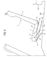
- a seat 1 for the third row of a motor vehicle comprises basically a seat cushion 2 and a seat backrest 3 hinged thereto about an axis 4, and can be moved from a normal-use position A, in which the seat is capable of receiving a person, to a non-use position B, in which the seat forms a loading area substantially flat and aligned with the vehicle floor.
- the seat 1 is provided with a double-lever driving mechanism 7 comprising a pair of rotating levers 9 and 10 mounted on the sides of the seat cushion 2 to allow the cushion to rotate about 180° forward and, at the same time, shift a predetermined extent backward.
- the levers 9 e 10 have their respective upper ends articulated to a body 5 for support of the seat cushion 2 and their respective lower ends articulated to a bracket-like sheet member (not visible in Figure 1) attached inside a lower room 15 of a vehicle floor 16.
- the movement of the seat from position A to position B controlled by the mechanism 7 involves the seat cushion 2 being completely overturned and put in the room 15 with its cushion surface 2a facing downward and its lower surface 2b facing upward and arranged substantially in alignment with the vehicle floor 16 and the seat backrest 3.
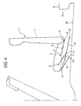
- a pair of seats 1 for a rear row of a motor vehicle are illustrated, each of the seats being of the type comprising a seat cushion 2 and a seat backrest 3 hinged thereto about an axis 4.
- the seats 1 are arranged, respectively, in a first position A, or use position, in which the seat is capable of receiving an occupant, and in a second position B, or non-use position, in which the seat is disposed upside-down inside a room 15 of the vehicle floor 16 with its upper surface substantially aligned with the loading platform of the vehicle.
- a double-lever mechanism 7 is provided on each side of the seat cushion 2, which mechanism comprises a front rotating lever 9 and a rear rotating lever 10 the upper ends 11 and 12 of which (with reference to the use position A illustrated in Figure 2) are articulated to the seat cushion 2.
- the lower end 14 of the rear lever 10 is articulated to a respective bracket 17, for example, attached to a side wall 15a of the room 15, whereas the lower end 13 of the front lever 9 is articulated at an intermediate point to a connecting rod 18 which forms, together with a crank 19, a crank mechanism 20 associated to the mechanism 7.
- the connecting rod 18 is articulated at a front end 21 to the crank 19 and is provided at the rear end with a slider 22 slidable in a substantially longitudinal direction along a straight guide 23 attached to the side wall 15a of the room 15.
- the connecting rod 18 has preferably a non-straight shape, with a first and a second straight segment 18a and 18b, respectively, inclined at an obtuse angle relative to each other, whereby the first segment 18a is arranged adjacent and substantially parallel to the front lever 9 of the mechanism 7 when the seat 1 is in the use position A.
- the point 13 of articulation of the lever 9 to the connecting rod 18 is positioned on the second straight segment 18b of the rod.
- the crank 19 is articulated to a bracket 25 arranged in the room 15, for example, attached to a bottom plane 15b of this room, at a front end 24 opposite to the end articulated to the connecting rod 18. Also the crank 19 has a preferably non-straight shape, with two straight segments inclined at an obtuse angle relative to each other.
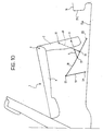
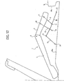
- the double-lever mechanism 7 and the crank mechanism 20 are arranged to form a driving device for moving the seat between the use position A ( Figure 3) and the non-use position B ( Figure 14) through a continuous movement, illustrated in Figure 4 to 13, which requires only one initial control by the user.
- the two driving devices each comprising a double-lever mechanism 7 and a crank mechanism 20, are arranged specularly at the opposite sides of each seat 1 and are also interconnected advantageously by means of a transverse rod 26 ( Figure 2), the lateral ends of which are fixed at the points of articulation 13.
- the use of the transverse rod 26 assures the synchronous operation of the two driving devices of each seat, thus facilitating the movement between the two positions A and B and avoiding the risk of jamming.
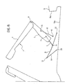
- the seat backrest 3 of the seat 1 is rotated frontward about the axis 4 of articulation to the seat cushion 2 ( Figure 4), until it assumes a substantially vertical orientation. Then, by pulling (or pushing) the seat backward, the seat is caused to lift and move back ( Figures 5 and 6) mainly by virtue of the clockwise rotation of the rotating levers 9 and 10 of the mechanism 7, the levers rotating initially almost synchronously and remaining substantially parallel to each other.
- the crank mechanism 20 is set in motion, though lightly, by virtue of the backward push that the lever 9 acting as a push-rod exerts on the crank 19 through the hinge 13.
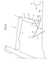
- the rotating levers 9 and 10 move towards a vertical position corresponding to an upper dead point of the mechanism 7, the backward movement of the seat tends to prevail on the lift movement.
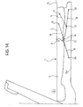
- the seat cushion 2 continues to rotate and move backward (Figures 11, 12 and 13) until it achieves at the end a completely overturned position, in which it abuts with the rear vertical wall 15c of the room 15 ( Figure 14) and has its lower surface 2b aligned with the vehicle floor 16.
- Figures 11 to 13 it can be seen also that an opening movement of the seat backrest 3 relative to the seat cushion takes place at the same time as the overturning of the seat cushion 2, due to the relative rotation of the two elements about the hinge axis 4, Therefore, at the end of the movement of the seat, the seat backrest 3 is aligned with the seat cushion 2 and the floor 16 to form a single loading platform.
- a seat according to the invention gives the advantage of enabling an increase in the load capacity inside the motor-vehicle passenger compartment, when the seat is in the non-use position, and of being easily movable between the use position and the non-use position.
- the seat cushion is only overturned 180 degrees, but remains substantially in the same longitudinal position. Therefore, due to the reduced free space between the two rows of seats it is necessary either to move at first the front seat in the non-use position, for example, by closing its cushion and backrest against each other, or to cause the seat backrest to pass below the seat cushion of the front seat during the movement from the use position to the non-use position. Such a necessity reduces unavoidably the ease and quickness of movement of the seat.
- crank mechanism 20 in co-operation with the double-lever mechanism 7, causes a backward movement of the seat which reduces significantly the free space between the two rows of seats required for the overturning of the rear seat.
- a further important advantage of the invention is that only one initial control is necessary to move the seat between the use and non-use positions, since the different movements of lifting, overturning and backward shifting of the seat cushion and of overturning of the seat backrest take place automatically in succession, just by virtue of the special arrangement of the driving system.
Landscapes
- Engineering & Computer Science (AREA)
- Aviation & Aerospace Engineering (AREA)
- Transportation (AREA)
- Mechanical Engineering (AREA)
- Seats For Vehicles (AREA)
- Automatic Cycles, And Cycles In General (AREA)
- Body Structure For Vehicles (AREA)
- Passenger Equipment (AREA)
Claims (8)
- Siège (1) pour une rangée arrière d'un véhicule automobile, du type comprenant un coussin de siège (2) et un dossier de siège (3) articulés (4) l'un avec l'autre et arrangés de manière à être déplacés entre une position d'utilisation (A), dans laquelle le siège peut recevoir un occupant, et une position de non-utilisation (B), dans laquelle le siège forme une zone de chargement sensiblement plate et alignée sur le sol du véhicule (16) ; dans lequel une paire de dispositifs d'entraínement sont prévus au niveau des côtés du coussin de siège (2) afin de déplacer le siège entre les positions précédentes (A, B) ; chaque dispositif comprenant un mécanisme à double levier (7) avec un levier rotatif avant (9) et un levier rotatif arrière (10) ; chacun des leviers (9, 10) ayant une extrémité articulée (11, 12) avec le coussin de siège (2) ; le levier arrière (10) étant aussi arrangé de manière rotative autour d'un premier point fixe (14) ;
caractérisé en ce que chaque dispositif d'entraínement comprend aussi un mécanisme à manivelle (20) avec une bielle (18) et une manivelle (19), associé au mécanisme à double levier (7) ; dans lequel la manivelle (19) est arrangée de manière rotative autour d'un second point fixe (24) et est articulée (21) avec la bielle (18), et la bielle (18) est prévue, au niveau de l'extrémité opposée à partir de celle qui est articulée avec la manivelle (19), avec un coulisseau (22) pouvant glisser dans une direction sensiblement longitudinale le long d'un guide droit respectif (23); la bielle (18) étant aussi articulée avec le levier avant (9) du mécanisme associé (7) dans un point intermédiaire (13) entre ses extrémités (21, 22). - Siège selon la revendication 1, caractérisé en ce que le levier avant (9) du mécanisme à double levier (7) est plus court que le levier arrière (10), de sorte que le levier avant tourne plus vite que le levier arrière en conséquence du mouvement vers l'arrière du siège, causant de cette manière une rotation vers l'avant du coussin de siège (2).
- Siège selon la revendication 1 ou 2, caractérisé en ce que la bielle (18) du mécanisme à manivelle (20) a des premier et second segments sensiblement droits (18a, 18b) inclinés à un angle obtus l'un par rapport à l'autre, dans lequel ledit premier segment est adjacent et sensiblement parallèle au levier avant (9) du mécanisme à double levier (7) quand le siège est dans la position d'utilisation (A).
- Siège selon la revendication 3, caractérisé en ce que aussi la manivelle (19) du mécanisme à manivelle (20) a une forme sensiblement d'angle obtus.
- Siège selon l'une quelconque des revendications précédentes, caractérisé en ce que les deux dispositifs d'entraínement sont arrangés pour déplacer le siège (1) entre les positions d'utilisation et de non-utilisation (A, B) par un mouvement continu en résultat d'une unique commande initiale transmise par l'utilisateur.
- Siège selon l'une quelconque des revendications précédentes, caractérisé en ce que les deux dispositifs d'entraínement sont interconnectés au moyen d'une tige transversale (26), dont les extrémités latérales sont fixées au niveau des points précédents d'articulation (13).
- Siège selon la revendication 1, caractérisé en ce que dans la position d'utilisation (A) le siège est arrangé au-dessus d'un espace (15) prévu dans le sol du véhicule (16), alors que dans la position de non-utilisation (B) le siège est entièrement logé dans l'espace (15) et sensiblement aligné avec le coussin de siège (2), avec le coussin de siège (2) retourné et le dossier de siège (3) arrangé horizontalement.
- Siège selon la revendication 7, caractérisé en ce que chaque guide droit (23) pour guider le mouvement de glissement du coulisseau (22) de la bielle respective (18) est fixé à une paroi verticale latérale (15a) de l'espace (15).
Applications Claiming Priority (2)
| Application Number | Priority Date | Filing Date | Title |
|---|---|---|---|
| IT2001TO000990A ITTO20010990A1 (it) | 2001-10-18 | 2001-10-18 | Sedile ribaltabile per una fila posteriore di un autoveicolo. |
| ITTO20010990 | 2001-10-18 |
Publications (3)
| Publication Number | Publication Date |
|---|---|
| EP1304256A2 EP1304256A2 (fr) | 2003-04-23 |
| EP1304256A3 EP1304256A3 (fr) | 2003-09-10 |
| EP1304256B1 true EP1304256B1 (fr) | 2005-01-19 |
Family
ID=11459267
Family Applications (1)
| Application Number | Title | Priority Date | Filing Date |
|---|---|---|---|
| EP02022862A Expired - Lifetime EP1304256B1 (fr) | 2001-10-18 | 2002-10-14 | Siège arrière rabattable pour véhicules automobiles |
Country Status (5)
| Country | Link |
|---|---|
| EP (1) | EP1304256B1 (fr) |
| AT (1) | ATE287348T1 (fr) |
| DE (1) | DE60202652T2 (fr) |
| ES (1) | ES2236419T3 (fr) |
| IT (1) | ITTO20010990A1 (fr) |
Families Citing this family (4)
| Publication number | Priority date | Publication date | Assignee | Title |
|---|---|---|---|---|
| DE10236490B4 (de) * | 2002-08-09 | 2005-06-23 | Faurecia Autositze Gmbh & Co. Kg | Kraftfahrzeugsitz |
| CA2454590C (fr) * | 2003-01-06 | 2007-07-03 | Faurecia Automotive Seating Canada Limited | Siege arriere escamotable pour habitacle de vehicule |
| DE10348085B4 (de) * | 2003-10-13 | 2005-10-13 | Johnson Controls Gmbh | Sitz mit schwenkbarem Sitzpolsterteil |
| DE10358720B4 (de) * | 2003-12-10 | 2013-06-06 | Volkswagen Ag | Kraftfahrzeugsitz mit getrennter Klappung von Sitzteil und Rückenlehnenteil |
Family Cites Families (7)
| Publication number | Priority date | Publication date | Assignee | Title |
|---|---|---|---|---|
| FR1577124A (fr) * | 1968-08-26 | 1969-08-01 | ||
| FR2411105A1 (fr) * | 1977-12-09 | 1979-07-06 | Peugeot | Siege transformable perfectionne pour vehicules automobiles |
| DE4422920A1 (de) * | 1994-06-30 | 1996-01-04 | Opel Adam Ag | Sitzanordnung, insbesondere für den Lade- bzw. Fahrgastraum eines Kraftfahrzeuges |
| DE19737304A1 (de) * | 1997-08-27 | 1999-03-04 | Opel Adam Ag | Sitz, insbesondere für eine dritte Sitzreihe eines Kraftfahrzeuges |
| DE19842824B4 (de) * | 1998-09-18 | 2010-09-30 | Volkswagen Ag | Sitzanordnung in einem Fahrzeug |
| DE19931013A1 (de) * | 1999-07-06 | 2001-01-11 | Volkswagen Ag | Klappbare Sitzanordnung in einem Kraftfahrzeug |
| DE19943891C1 (de) * | 1999-09-14 | 2000-11-16 | Faure Bertrand Sitztech Gmbh | Sitz oder Sitzbank für den Kofferraum- bzw. Laderaumbereich eines Kraftfahrzeuges |
-
2001
- 2001-10-18 IT IT2001TO000990A patent/ITTO20010990A1/it unknown
-
2002
- 2002-10-14 EP EP02022862A patent/EP1304256B1/fr not_active Expired - Lifetime
- 2002-10-14 ES ES02022862T patent/ES2236419T3/es not_active Expired - Lifetime
- 2002-10-14 DE DE60202652T patent/DE60202652T2/de not_active Expired - Lifetime
- 2002-10-14 AT AT02022862T patent/ATE287348T1/de not_active IP Right Cessation
Also Published As
| Publication number | Publication date |
|---|---|
| DE60202652D1 (de) | 2005-02-24 |
| ES2236419T3 (es) | 2005-07-16 |
| DE60202652T2 (de) | 2006-01-05 |
| EP1304256A2 (fr) | 2003-04-23 |
| ATE287348T1 (de) | 2005-02-15 |
| ITTO20010990A1 (it) | 2003-04-18 |
| EP1304256A3 (fr) | 2003-09-10 |
Similar Documents
| Publication | Publication Date | Title |
|---|---|---|
| EP1892143B1 (fr) | Assemblage du siège d'un véhicule | |
| CN111601732B (zh) | 便捷进入的车辆座椅 | |
| CN110979112B (zh) | 车辆座椅 | |
| KR101058762B1 (ko) | 차량용 시트 장치 | |
| CN112124158B (zh) | 带可倾斜靠背的车辆座椅 | |
| US7066539B2 (en) | Vehicle seat of retractable type | |
| US7607735B2 (en) | Vehicle seats | |
| US4215899A (en) | Cabin for trucks with trailer-fixtures | |
| EP2075153B1 (fr) | Ensemble de siège d'un véhicule automobile, équipé d'un plancher de charge pour un coffre arrière | |
| WO2006030539A1 (fr) | Dispositif d'entrée | |
| KR20230064716A (ko) | 자동차용 시트 조절 장치 | |
| CN105452054A (zh) | 用于下沉式车辆座椅的便捷进入调整机构以及座椅装置 | |
| JP2008049845A (ja) | 自動車用シート装置 | |
| EP1304256B1 (fr) | Siège arrière rabattable pour véhicules automobiles | |
| EP2046600B1 (fr) | Ensemble de siège muni d'un dispositif de support quadrilatéral articulé pour un véhicule à moteur | |
| US7413232B1 (en) | Vehicle seat lifting unit | |
| KR20050063665A (ko) | 승용물용 시트 | |
| JP2003040010A (ja) | チップアップ機構付の車両用シート | |
| JP4019705B2 (ja) | シート装置 | |
| JP2008049847A (ja) | 自動車用シート装置 | |
| JP2001063420A (ja) | 車両のシート装置 | |
| JP4688215B2 (ja) | 車両用シート | |
| KR0138699Y1 (ko) | 자동차 시트의 접힘구조 | |
| JP4112761B2 (ja) | 車両のフラット化シート構造 | |
| JP3801237B2 (ja) | 車両における座席の昇降装置 |
Legal Events
| Date | Code | Title | Description |
|---|---|---|---|
| PUAI | Public reference made under article 153(3) epc to a published international application that has entered the european phase |
Free format text: ORIGINAL CODE: 0009012 |
|
| AK | Designated contracting states |
Designated state(s): AT BE BG CH CY CZ DE DK EE ES FI FR GB GR IE IT LI LU MC NL PT SE SK TR |
|
| AX | Request for extension of the european patent |
Extension state: AL LT LV MK RO SI |
|
| PUAL | Search report despatched |
Free format text: ORIGINAL CODE: 0009013 |
|
| AK | Designated contracting states |
Kind code of ref document: A3 Designated state(s): AT BE BG CH CY CZ DE DK EE ES FI FR GB GR IE IT LI LU MC NL PT SE SK TR |
|
| AX | Request for extension of the european patent |
Extension state: AL LT LV MK RO SI |
|
| GRAP | Despatch of communication of intention to grant a patent |
Free format text: ORIGINAL CODE: EPIDOSNIGR1 |
|
| 17P | Request for examination filed |
Effective date: 20040304 |
|
| AKX | Designation fees paid |
Designated state(s): AT BE BG CH CY CZ DE DK EE ES FI FR GB GR IE IT LI LU MC NL PT SE SK TR |
|
| GRAS | Grant fee paid |
Free format text: ORIGINAL CODE: EPIDOSNIGR3 |
|
| RAP1 | Party data changed (applicant data changed or rights of an application transferred) |
Owner name: WIDE DESIGN S.P.A. |
|
| RAP1 | Party data changed (applicant data changed or rights of an application transferred) |
Owner name: ITALDESIGN-GIUGIARO S.P.A |
|
| GRAA | (expected) grant |
Free format text: ORIGINAL CODE: 0009210 |
|
| AK | Designated contracting states |
Kind code of ref document: B1 Designated state(s): AT BE BG CH CY CZ DE DK EE ES FI FR GB GR IE IT LI LU MC NL PT SE SK TR |
|
| PG25 | Lapsed in a contracting state [announced via postgrant information from national office to epo] |
Ref country code: LI Free format text: LAPSE BECAUSE OF FAILURE TO SUBMIT A TRANSLATION OF THE DESCRIPTION OR TO PAY THE FEE WITHIN THE PRESCRIBED TIME-LIMIT Effective date: 20050119 Ref country code: BE Free format text: LAPSE BECAUSE OF FAILURE TO SUBMIT A TRANSLATION OF THE DESCRIPTION OR TO PAY THE FEE WITHIN THE PRESCRIBED TIME-LIMIT Effective date: 20050119 Ref country code: FI Free format text: LAPSE BECAUSE OF FAILURE TO SUBMIT A TRANSLATION OF THE DESCRIPTION OR TO PAY THE FEE WITHIN THE PRESCRIBED TIME-LIMIT Effective date: 20050119 Ref country code: AT Free format text: LAPSE BECAUSE OF FAILURE TO SUBMIT A TRANSLATION OF THE DESCRIPTION OR TO PAY THE FEE WITHIN THE PRESCRIBED TIME-LIMIT Effective date: 20050119 Ref country code: BG Free format text: LAPSE BECAUSE OF FAILURE TO SUBMIT A TRANSLATION OF THE DESCRIPTION OR TO PAY THE FEE WITHIN THE PRESCRIBED TIME-LIMIT Effective date: 20050119 Ref country code: TR Free format text: LAPSE BECAUSE OF FAILURE TO SUBMIT A TRANSLATION OF THE DESCRIPTION OR TO PAY THE FEE WITHIN THE PRESCRIBED TIME-LIMIT Effective date: 20050119 Ref country code: NL Free format text: LAPSE BECAUSE OF FAILURE TO SUBMIT A TRANSLATION OF THE DESCRIPTION OR TO PAY THE FEE WITHIN THE PRESCRIBED TIME-LIMIT Effective date: 20050119 Ref country code: EE Free format text: LAPSE BECAUSE OF FAILURE TO SUBMIT A TRANSLATION OF THE DESCRIPTION OR TO PAY THE FEE WITHIN THE PRESCRIBED TIME-LIMIT Effective date: 20050119 Ref country code: CH Free format text: LAPSE BECAUSE OF FAILURE TO SUBMIT A TRANSLATION OF THE DESCRIPTION OR TO PAY THE FEE WITHIN THE PRESCRIBED TIME-LIMIT Effective date: 20050119 Ref country code: CZ Free format text: LAPSE BECAUSE OF FAILURE TO SUBMIT A TRANSLATION OF THE DESCRIPTION OR TO PAY THE FEE WITHIN THE PRESCRIBED TIME-LIMIT Effective date: 20050119 Ref country code: SK Free format text: LAPSE BECAUSE OF FAILURE TO SUBMIT A TRANSLATION OF THE DESCRIPTION OR TO PAY THE FEE WITHIN THE PRESCRIBED TIME-LIMIT Effective date: 20050119 Ref country code: IT Free format text: LAPSE BECAUSE OF FAILURE TO SUBMIT A TRANSLATION OF THE DESCRIPTION OR TO PAY THE FEE WITHIN THE PRESCRIBED TIME-LIMIT;WARNING: LAPSES OF ITALIAN PATENTS WITH EFFECTIVE DATE BEFORE 2007 MAY HAVE OCCURRED AT ANY TIME BEFORE 2007. THE CORRECT EFFECTIVE DATE MAY BE DIFFERENT FROM THE ONE RECORDED. Effective date: 20050119 |
|
| REG | Reference to a national code |
Ref country code: GB Ref legal event code: FG4D |
|
| REG | Reference to a national code |
Ref country code: CH Ref legal event code: EP |
|
| REG | Reference to a national code |
Ref country code: IE Ref legal event code: FG4D |
|
| REF | Corresponds to: |
Ref document number: 60202652 Country of ref document: DE Date of ref document: 20050224 Kind code of ref document: P |
|
| PG25 | Lapsed in a contracting state [announced via postgrant information from national office to epo] |
Ref country code: GR Free format text: LAPSE BECAUSE OF FAILURE TO SUBMIT A TRANSLATION OF THE DESCRIPTION OR TO PAY THE FEE WITHIN THE PRESCRIBED TIME-LIMIT Effective date: 20050419 Ref country code: DK Free format text: LAPSE BECAUSE OF FAILURE TO SUBMIT A TRANSLATION OF THE DESCRIPTION OR TO PAY THE FEE WITHIN THE PRESCRIBED TIME-LIMIT Effective date: 20050419 |
|
| REG | Reference to a national code |
Ref country code: SE Ref legal event code: TRGR |
|
| NLV1 | Nl: lapsed or annulled due to failure to fulfill the requirements of art. 29p and 29m of the patents act | ||
| REG | Reference to a national code |
Ref country code: ES Ref legal event code: FG2A Ref document number: 2236419 Country of ref document: ES Kind code of ref document: T3 |
|
| REG | Reference to a national code |
Ref country code: CH Ref legal event code: PL |
|
| PG25 | Lapsed in a contracting state [announced via postgrant information from national office to epo] |
Ref country code: IE Free format text: LAPSE BECAUSE OF NON-PAYMENT OF DUE FEES Effective date: 20051014 Ref country code: CY Free format text: LAPSE BECAUSE OF FAILURE TO SUBMIT A TRANSLATION OF THE DESCRIPTION OR TO PAY THE FEE WITHIN THE PRESCRIBED TIME-LIMIT Effective date: 20051014 |
|
| PG25 | Lapsed in a contracting state [announced via postgrant information from national office to epo] |
Ref country code: MC Free format text: LAPSE BECAUSE OF NON-PAYMENT OF DUE FEES Effective date: 20051031 Ref country code: LU Free format text: LAPSE BECAUSE OF NON-PAYMENT OF DUE FEES Effective date: 20051031 |
|
| PLBE | No opposition filed within time limit |
Free format text: ORIGINAL CODE: 0009261 |
|
| STAA | Information on the status of an ep patent application or granted ep patent |
Free format text: STATUS: NO OPPOSITION FILED WITHIN TIME LIMIT |
|
| ET | Fr: translation filed | ||
| 26N | No opposition filed |
Effective date: 20051020 |
|
| REG | Reference to a national code |
Ref country code: IE Ref legal event code: MM4A |
|
| PG25 | Lapsed in a contracting state [announced via postgrant information from national office to epo] |
Ref country code: PT Free format text: LAPSE BECAUSE OF NON-PAYMENT OF DUE FEES Effective date: 20050619 |
|
| REG | Reference to a national code |
Ref country code: FR Ref legal event code: PLFP Year of fee payment: 14 |
|
| REG | Reference to a national code |
Ref country code: FR Ref legal event code: PLFP Year of fee payment: 15 |
|
| REG | Reference to a national code |
Ref country code: FR Ref legal event code: PLFP Year of fee payment: 16 |
|
| REG | Reference to a national code |
Ref country code: FR Ref legal event code: PLFP Year of fee payment: 17 |
|
| PGFP | Annual fee paid to national office [announced via postgrant information from national office to epo] |
Ref country code: SE Payment date: 20191016 Year of fee payment: 18 Ref country code: DE Payment date: 20191031 Year of fee payment: 18 |
|
| PGFP | Annual fee paid to national office [announced via postgrant information from national office to epo] |
Ref country code: ES Payment date: 20191105 Year of fee payment: 18 |
|
| PGFP | Annual fee paid to national office [announced via postgrant information from national office to epo] |
Ref country code: GB Payment date: 20191021 Year of fee payment: 18 |
|
| PGFP | Annual fee paid to national office [announced via postgrant information from national office to epo] |
Ref country code: FR Payment date: 20200114 Year of fee payment: 18 |
|
| REG | Reference to a national code |
Ref country code: DE Ref legal event code: R119 Ref document number: 60202652 Country of ref document: DE |
|
| REG | Reference to a national code |
Ref country code: SE Ref legal event code: EUG |
|
| GBPC | Gb: european patent ceased through non-payment of renewal fee |
Effective date: 20201014 |
|
| PG25 | Lapsed in a contracting state [announced via postgrant information from national office to epo] |
Ref country code: DE Free format text: LAPSE BECAUSE OF NON-PAYMENT OF DUE FEES Effective date: 20210501 Ref country code: FR Free format text: LAPSE BECAUSE OF NON-PAYMENT OF DUE FEES Effective date: 20201031 |
|
| PG25 | Lapsed in a contracting state [announced via postgrant information from national office to epo] |
Ref country code: SE Free format text: LAPSE BECAUSE OF NON-PAYMENT OF DUE FEES Effective date: 20201015 Ref country code: GB Free format text: LAPSE BECAUSE OF NON-PAYMENT OF DUE FEES Effective date: 20201014 |
|
| REG | Reference to a national code |
Ref country code: ES Ref legal event code: FD2A Effective date: 20220121 |
|
| PG25 | Lapsed in a contracting state [announced via postgrant information from national office to epo] |
Ref country code: ES Free format text: LAPSE BECAUSE OF NON-PAYMENT OF DUE FEES Effective date: 20201015 |