EP1305464B1 - Anordnungen und verfahren zum stabilisieren von drehbaren schablonen zum pneumatischen prägen von warenbahnen - Google Patents
Anordnungen und verfahren zum stabilisieren von drehbaren schablonen zum pneumatischen prägen von warenbahnen Download PDFInfo
- Publication number
- EP1305464B1 EP1305464B1 EP01955039A EP01955039A EP1305464B1 EP 1305464 B1 EP1305464 B1 EP 1305464B1 EP 01955039 A EP01955039 A EP 01955039A EP 01955039 A EP01955039 A EP 01955039A EP 1305464 B1 EP1305464 B1 EP 1305464B1
- Authority
- EP
- European Patent Office
- Prior art keywords
- stencil
- air
- fabric
- nozzle
- lance
- Prior art date
- Legal status (The legal status is an assumption and is not a legal conclusion. Google has not performed a legal analysis and makes no representation as to the accuracy of the status listed.)
- Expired - Lifetime
Links
- 239000004744 fabric Substances 0.000 title claims abstract description 299
- 238000004049 embossing Methods 0.000 title claims abstract description 227
- 238000000034 method Methods 0.000 title claims abstract description 58
- 230000000087 stabilizing effect Effects 0.000 title description 17
- 239000003381 stabilizer Substances 0.000 claims abstract description 107
- 238000000926 separation method Methods 0.000 claims description 46
- 238000011144 upstream manufacturing Methods 0.000 claims description 17
- 230000007704 transition Effects 0.000 abstract description 5
- 239000000835 fiber Substances 0.000 description 36
- 239000010410 layer Substances 0.000 description 35
- 238000009826 distribution Methods 0.000 description 22
- 239000000758 substrate Substances 0.000 description 22
- 239000000853 adhesive Substances 0.000 description 21
- 230000001070 adhesive effect Effects 0.000 description 21
- 239000012790 adhesive layer Substances 0.000 description 16
- 230000008569 process Effects 0.000 description 16
- 230000007246 mechanism Effects 0.000 description 15
- 238000013461 design Methods 0.000 description 14
- 239000000463 material Substances 0.000 description 14
- 239000007789 gas Substances 0.000 description 9
- 238000004519 manufacturing process Methods 0.000 description 7
- 230000005855 radiation Effects 0.000 description 7
- 230000006641 stabilisation Effects 0.000 description 7
- 238000011105 stabilization Methods 0.000 description 7
- 230000000007 visual effect Effects 0.000 description 7
- 238000004140 cleaning Methods 0.000 description 6
- 125000006850 spacer group Chemical group 0.000 description 6
- 229910052782 aluminium Inorganic materials 0.000 description 5
- XAGFODPZIPBFFR-UHFFFAOYSA-N aluminium Chemical compound [Al] XAGFODPZIPBFFR-UHFFFAOYSA-N 0.000 description 5
- 239000011248 coating agent Substances 0.000 description 5
- 238000000576 coating method Methods 0.000 description 5
- 238000004891 communication Methods 0.000 description 5
- 239000012530 fluid Substances 0.000 description 5
- 239000007787 solid Substances 0.000 description 5
- 244000144992 flock Species 0.000 description 4
- 239000004922 lacquer Substances 0.000 description 4
- 239000002184 metal Substances 0.000 description 4
- 229910052751 metal Inorganic materials 0.000 description 4
- 238000007639 printing Methods 0.000 description 4
- 230000000712 assembly Effects 0.000 description 3
- 238000000429 assembly Methods 0.000 description 3
- 238000005520 cutting process Methods 0.000 description 3
- 238000000151 deposition Methods 0.000 description 3
- 239000006185 dispersion Substances 0.000 description 3
- 238000005516 engineering process Methods 0.000 description 3
- 239000000203 mixture Substances 0.000 description 3
- 238000012986 modification Methods 0.000 description 3
- 230000004048 modification Effects 0.000 description 3
- 239000004033 plastic Substances 0.000 description 3
- 229920003023 plastic Polymers 0.000 description 3
- 229920001343 polytetrafluoroethylene Polymers 0.000 description 3
- 239000004810 polytetrafluoroethylene Substances 0.000 description 3
- XLYOFNOQVPJJNP-UHFFFAOYSA-N water Substances O XLYOFNOQVPJJNP-UHFFFAOYSA-N 0.000 description 3
- 239000002759 woven fabric Substances 0.000 description 3
- PXHVJJICTQNCMI-UHFFFAOYSA-N Nickel Chemical compound [Ni] PXHVJJICTQNCMI-UHFFFAOYSA-N 0.000 description 2
- 239000000654 additive Substances 0.000 description 2
- 230000008901 benefit Effects 0.000 description 2
- 230000000295 complement effect Effects 0.000 description 2
- 230000007547 defect Effects 0.000 description 2
- 235000004879 dioscorea Nutrition 0.000 description 2
- 238000006073 displacement reaction Methods 0.000 description 2
- 230000000694 effects Effects 0.000 description 2
- 238000003780 insertion Methods 0.000 description 2
- 230000037431 insertion Effects 0.000 description 2
- 238000009434 installation Methods 0.000 description 2
- 238000007790 scraping Methods 0.000 description 2
- 229920002994 synthetic fiber Polymers 0.000 description 2
- 239000012209 synthetic fiber Substances 0.000 description 2
- 241000272194 Ciconiiformes Species 0.000 description 1
- 229920000742 Cotton Polymers 0.000 description 1
- 210000004712 air sac Anatomy 0.000 description 1
- 239000003831 antifriction material Substances 0.000 description 1
- 239000003125 aqueous solvent Substances 0.000 description 1
- 230000015572 biosynthetic process Effects 0.000 description 1
- 239000003054 catalyst Substances 0.000 description 1
- 230000008859 change Effects 0.000 description 1
- 239000003086 colorant Substances 0.000 description 1
- 238000007796 conventional method Methods 0.000 description 1
- 230000003247 decreasing effect Effects 0.000 description 1
- 230000008021 deposition Effects 0.000 description 1
- 230000001627 detrimental effect Effects 0.000 description 1
- 238000010586 diagram Methods 0.000 description 1
- 238000001035 drying Methods 0.000 description 1
- 230000005684 electric field Effects 0.000 description 1
- 230000005686 electrostatic field Effects 0.000 description 1
- 230000001788 irregular Effects 0.000 description 1
- 238000003698 laser cutting Methods 0.000 description 1
- 238000003754 machining Methods 0.000 description 1
- 238000012423 maintenance Methods 0.000 description 1
- 238000005259 measurement Methods 0.000 description 1
- 150000002739 metals Chemical class 0.000 description 1
- 229910052759 nickel Inorganic materials 0.000 description 1
- 239000004745 nonwoven fabric Substances 0.000 description 1
- 229920001778 nylon Polymers 0.000 description 1
- 239000003973 paint Substances 0.000 description 1
- 238000010422 painting Methods 0.000 description 1
- 239000004014 plasticizer Substances 0.000 description 1
- 229920000058 polyacrylate Polymers 0.000 description 1
- 239000002861 polymer material Substances 0.000 description 1
- -1 polytetrafluoroethylene Polymers 0.000 description 1
- 238000012545 processing Methods 0.000 description 1
- 230000009467 reduction Effects 0.000 description 1
- 229920005989 resin Polymers 0.000 description 1
- 239000011347 resin Substances 0.000 description 1
- 238000010022 rotary screen printing Methods 0.000 description 1
- 238000007650 screen-printing Methods 0.000 description 1
- 238000012216 screening Methods 0.000 description 1
- 238000005507 spraying Methods 0.000 description 1
- 229920001059 synthetic polymer Polymers 0.000 description 1
- 229920001187 thermosetting polymer Polymers 0.000 description 1
- 238000012546 transfer Methods 0.000 description 1
- 239000004034 viscosity adjusting agent Substances 0.000 description 1
- 238000003466 welding Methods 0.000 description 1
Images







Classifications
-
- D—TEXTILES; PAPER
- D06—TREATMENT OF TEXTILES OR THE LIKE; LAUNDERING; FLEXIBLE MATERIALS NOT OTHERWISE PROVIDED FOR
- D06C—FINISHING, DRESSING, TENTERING OR STRETCHING TEXTILE FABRICS
- D06C23/00—Making patterns or designs on fabrics
- D06C23/04—Making patterns or designs on fabrics by shrinking, embossing, moiréing, or crêping
Definitions
- the present application relates to systems and methods for embossing a surface of an embossable fabric with a stream of air or other gas, and embossed flocked fabrics made thereby, and more specifically to systems and methods for stabilizing the rotation of a cylindrical embossing stencil utilized for embossing a surface of an embossable fabric with a stream of air or other gas.
- flocked fabric In manufacturing flocked fabric it is conventional to deposit a layer of flock on an adhesive coated substrate and to emboss the surface of the flocked fabric during this process with selected designs.
- the embossing process may be achieved by one of several processes using specialized equipment for such purposes. Among these embossing processes is air embossing.
- a substrate In the air embossing process a substrate is coated with an adhesive. While the adhesive is still wet it is covered with a layer of flock fibers forming the flocked layer.
- the adhesive coated substrate with the flocked fibers is then carried beneath a stencil while the adhesive is not yet set.
- the stencil under which the assembly moves typically comprises an elongated cylinder having perforations arranged in a desired pattern to be formed in the flocked surface.
- This embossing stencil typically is rotated at the same speed as the flocked layer moves beneath it. Air introduced within this cylindrical stencil is directed downwardly through the perforations forming the pattern onto the upper surface of the flocked layer.
- Air jets are directed downwardly from the stencil and onto the surface of the flocked fabric. Since the flocked fabric has not yet set in the adhesive, the stream of air changes the angle of or substantially flattens the flock fibers forming the flock in selected areas, thus forming a pattern as the stencil rotates and the flocked fabric moves.
- a variety of prior art systems are available for performing air embossing of flocked fabrics. Many such systems are generally satisfactory for embossing designs onto an embossable surface of the fabric that do not require a significant level of fine detail.
- typical prior art systems suffer from a variety of shortcoming which limit their utility for producing finely detailed patterns, and which result in embossed pile fabrics that include embossed regions having undesirable artifacts and visually unappealing surface features.
- air embossed pile fabrics produced with conventional air embossing equipment are typically not able to produce embossed features having a characteristic size that is very small, thus such equipment is not able to give the embossed fabric an appearance with a fine, detailed surface structure.
- typical prior art air embossing systems are not able to direct air towards the embossable surface of the fabric at a controlled, desirable angle (e.g. essentially perpendicular to the fabric surface), and, thus, they tend to produce embossed features having a blurred or imprecise transition region between the embossed features and the unembossed regions of the surface, which results in an associated lack of crispness and definition to the overall appearance of the embossed fabric.
- typical prior art air embossing systems also tend to produce embossed fabrics having embossed features distributed across the width of the fabric that are not uniform in appearance across the width of the fabric.
- typical prior art air embossing systems have a tendency to direct air towards the surface of the fabric in a direction diagonal to the fabric surface resulting in an embossed surface wherein the pile fibers have an overall directional lay with respect to the substrate, thus creating a distorted, unattractive appearance in the embossed surface, which appearance does not accurately reflect the pattern provided in the stencil used for embossing.
- typical prior art air embossing systems utilize embossing stencils which often, because of manufacturing defects/tolerances and/or damage during use, do not rotate "true” (i.e. the distance between the outer surface of the stencil and the rotational axis of the cylinder is not constant around the circumference of the stencil), but rather include a substantial degree of "run out”.
- "Run out” during rotation of many typical prior art air embossing stencils is caused by a deviation from a circular cross-sectional shape of the embossing stencil (taken in a plane perpendicular to its longitudinal axis) and/or a displacement of the rotational axis if the stencil with respect to the longitudinal centerline of the stencil.
- Some aspects and embodiments of the present disclosure are directed to improved air embossing systems and methods and improved embossed fabrics produced using the systems and methods.
- the present disclosure describes a variety of air embossing systems utilizing improved air lances for directing air onto and through a patterned stencil of the system and/or including stencil stabilizers to reduce the "run out” in stencils and increase the uniformity of the distance separating the portion of the outer embossing surface of the stencil adjacent to the fabric from the embossable surface of the fabric during rotation.
- the improved air lances and embossing systems described herein are able, in many embodiments, to solve many of the above mentioned shortcomings of prior art air embossing systems and to produce embossed fabrics having an unprecedented level of fine detail, crisp transition between unembossed and embossed regions, lack of undesired artefacts due to non-uniformity in the distance separating the portion of the stencil adjacent the fabric from the fabric during rotation, and uniformity of the pattern across the width of the embossed fabric.
- the present invention involves, in some embodiments, an improved air embossing system which is able to produce an unprecedented level of fine detail, crisp transition between unembossed and embossed regions, a high degree of uniformity across the width of an embossed fabric, and a lack of undesired artefacts due to non-uniformity in the distance separating the portion of the stencil adjacent the fabric from the fabric during rotation, when compared to the performance of typical, conventional air embossing systems.
- a system for embossing a surface of an embossable fabric using gas comprising a cylindrical stencil having an inside surface and a fabric-facing surface and a lance including at least one nozzle thereon positioned with respect to the inside surface of the stencil so that it is able to emit a stream of the gas such that the gas is directed to pass through at least one opening in the stencil and when the system is in operation impinge upon the embossable surface of the fabric, the stream of gas having sufficient velocity and collimation to create a visible embossed depression in the surface of the fabric in a pattern corresponding to a pattern characterising the at least one opening in the stencil is known from US-A-3916823.
- a system for embossing a surface of an embossable fabric using gas according to the invention is characterised by at least one stencil stabilizer operable to apply a force to the inside surface of the stencil during operation of the system, to reduce variations in a distance separating the embossable surface of the fabric and a portion of the fabric-facing surface of the stencil directly adjacent thereto during rotation of the stencil.
- the at least one nozzle of the air embossing system may have a characteristic orifice dimension substantially less than that of conventional air lance nozzles.
- the disclosed air embossing system can also include air lances having nozzles positioned in close proximity to the embossable surface of a fabric being embossed, substantially closer than is typical for air lances employed in conventional air embossing systems and in some preferred embodiments, the nozzles can be positioned in direct contact with an inner surface of the air embossing stencil.
- the air lance can also include one or more nozzles having a characteristic orifice dimension that is substantially less than a characteristic length of the nozzles or one or more nozzles in the shape of an elongated slit oriented, with respect to the air lance, so as to be positioned across essentially the entire width of a fabric being embossed.
- the air lance of the embossing system may also include a nozzle-forming component that is separable from the main body of the air lance and that enables the nozzle(s) of the air lance to be positioned within close proximity to the fabric, when the air lance is in operation, and that also can act to redirect air flowing within the air lance such that it is emitted from the nozzle(s) so that a substantial fraction of the air stream is directed essentially perpendicular to the surface of the fabric being embossed.
- a nozzle-forming component that is separable from the main body of the air lance and that enables the nozzle(s) of the air lance to be positioned within close proximity to the fabric, when the air lance is in operation, and that also can act to redirect air flowing within the air lance such that it is emitted from the nozzle(s) so that a substantial fraction of the air stream is directed essentially perpendicular to the surface of the fabric being embossed.
- the air lance includes one or more baffles or air redirecting elements, which serve to deflect air flowing within the air lance so that it passes through the nozzle(s) and is directed onto the embossable surface of the fabric at an angle that is substantially greater, with respect to the longitudinal axis of the air lance, than the angle of an air stream emitted from a nozzle of an essentially equivalent air lance, except excluding the air redirecting element or baffle.
- Some of the air lances of the system described can include a combination of several or all of the above described features.
- US-A-4 497 249 discloses a machine (preferably a printing machine) having a flexible rotary screen and an arrangement which internally supports the screen against deformation, in particular for maintaining the screen round in its cross-section.
- the present disclosure describes a variety of improved air embossing systems and methods of operation of air embossing systems that includes embodiments that are able to improve the performance of such systems and result in the production of embossed fabrics which can have an unprecedented level of fine detail and uniformity to the embossed pattern and a lack of undesirable artifacts in the embossed pattern.
- an important factor in the performance of air embossing systems is the design and positioning of the air lance, which distributes air through a patterned stencil and onto the surface of the fabric, within the system.
- the present disclosure describes, in the context of some embodiments, a variety of improved air lance designs and improved systems for positioning the air lance with respect to the stencil and fabric.
- the present invention is broadly directed to methods and systems for air embossing an embossable fabric. It should be understood that while the invention is described in the embodiments below in the context of embossable fabrics comprising flocked, pile fabrics, that the invention is not so limited and that an embossable fabric as used herein encompasses any fabric having at least one embossable surface.
- An "embossable surface” refers to a surface that can be permanently or temporarily visibly altered by an air stream impinging thereon.
- the present invention is described as utilizing air for embossing an embossable surface of a fabric, it should be understood that other gases may be substituted for air, as would be apparent to those of ordinary skill in the art.
- the air embossing systems disclosed can include an air lance directing a stream of air directly onto the embossable surface of an embossable fabric to form a pattern thereon, in preferred embodiments, the air stream from the air lance is directed through a stencil before impinging upon the surface of the fabric.
- a "stencil" as used herein defines a gas impermeable surface having a plurality of apertures therein oriented in a pattern on the surface.
- the air directed from the air lance onto the surface of the stencil is interrupted by the solid, gas-impermeable stencil but passes relatively freely through the openings or apertures within the stencil, thus forming an embossed pattern on the surface of the fabric dictated by the pattern of apertures within the stencil.
- Stencils for use within the context of the invention can comprise flat or cylindrical surfaces, and the surfaces can be stationary or movable with respect to the embossable surface of the fabric during operation of the air embossing system.
- Preferred systems utilize a rotatable, hollow cylindrical stencil disposed across essentially the entire width of the embossable surface of the fabric and having an air lance disposed therein.
- an “air lance” as used herein refers broadly to a conduit, manifold, or other object able to direct a stream of air onto the surface of a stencil and/or embossable fabric.
- the air lance comprises an elongated conduit, extending across essentially the entire width of the fabric that is embossed by the system, which includes at least one nozzle for directing the stream of air.
- a "nozzle,” as used herein, refers to the smallest orifice within the air lance through which an air stream passes.
- an "orifice,” or “opening” as used herein in the context of the nozzle or nozzles refers to a planar or contoured interfacial area providing a transition between a region of the air lance in which the air stream is confined on at least two adjacent and opposed sides, defining a smallest cross-sectional dimension of the air stream, by surfaces aligned essentially parallel, or having a component in the coordinate direction parallel to but having overall orientation that is angled with respect to the direction of bulk flow of the air stream, and a region, which may be external to the air lance, wherein the air stream is unconfined on at least one of such two adjacent and opposed sides.
- some of the air lances disclosed can include a plurality of discrete nozzles therein, for example, a plurality of nozzles comprising individual holes within the air lance, each of which direct a stream of air toward the surface of an embossable fabric.
- each of such holes comprises a "nozzle.”
- the nozzles are not all of the same size, or where the air lance includes a nozzle having a characteristic dimension that is non-uniform along the length of the air lance
- the "smallest orifice in the air lance through which an air stream passes" which defines a "nozzle” refers to the smallest orifice in the lance through which any portion or component of the air stream passes.
- the smallest orifice through which any given molecule or atom of the air stream passes before exiting the air lance comprises a "nozzle".
- the nozzle or nozzles within the air lance are constructed and positioned to direct a stream of air through at least one opening in a stencil and onto an embossable surface of the fabric.
- the term "constructed and positioned to direct a stream of air through at least one opening in a stencil and onto an embossable surface" of a fabric as used herein refers to the nozzle(s) being sized and positioned within the air embossing system such that at least a portion of an air stream emitted from the nozzle(s) is directed through an opening of the stencil and onto the embossable surface of the fabric.
- Conventional prior art air lances utilized for air embossing fabrics typically comprise a long tubular conduit having a single row of holes extending lengthwise along the tube so that they traverse the width of the fabric when the air lance is positioned for use.
- the holes comprising nozzles of the air lance, in prior art configurations, are typically relatively large in diameter (e.g., greater than about 6.35 mm (0.25 inch) in diameter).
- the open area in the air lance formed by the nozzles also, in conventional designs, is at least about 40 % of the internal cross sectional area of the main body of the air lance.
- the nozzles are positioned spaced apart from the stencil through which the air is directed by a relatively large distance of at least about 1 inch.
- the above-described conventional air lance designs are not well suited for producing finely detailed embossed patterns in fabrics, which patterns have a uniform visual appearance across the width of the embossed fabric.
- Such finely detailed embossed patterns in fabrics are highly desirable in the marketplace and are enabled and provided by many of the improved systems and methods disclosed herein.
- the air lances and air embossing systems utilizing the air lances disclosed herein can include a variety of improvements over the above-described prior art system, which improvements, alone or in combination, can solve many of the above-mentioned problems inherent in the prior art systems.
- some embodiments of the disclosed air embossing systems can include air lances that are designed so that the distance separating the nozzle(s) from the stencil is significantly less than for prior art systems.
- air embossing systems can include air lances having a nozzle(s) with a characteristic dimension smaller than typical prior art nozzle sizes.
- the air lances can include a nozzle(s) having a total open area that is significantly smaller with respect to a cross-sectional area of a conduit comprising the main body of the air lance than for typical prior art air lances.
- an embossing method that involves emitting an air stream from the nozzle(s) of the air lance at a velocity that is significantly higher than that created by conventional air embossing systems can be utilized.
- the air lances also can include nozzle(s) formed in the shape of a continuous slit, as opposed to the discrete holes comprising nozzles typically included in conventional air lances.
- the air lances can include air redirecting elements or baffles therein, and/or nozzles that are shaped to create more focused and collimated air flow therethrough when compared to conventional air lance nozzles.
- one or more stencil stabilizers configured to apply a force to a rotating stencil of the system during operation thereby reducing any variations in the distance separating the embossable surface of a fabric being embossed with the system and that portion of the fabric-facing surface of the stencil directly adjacent to the embossable surface during rotation of the stencil can be provided.
- air embossing systems and air lances as disclosed herein can create, in some embodiments, a fabric embossing air stream having a high degree of collimation, a low degree of turbulence, and a high flow velocity, yielding better definition and more fine detail in fabric surfaces embossed with the inventive systems.
- the disclosed systems also can include air lances which can emit an air stream having a more even and uniform air flow velocity distribution across the entire width of the air lance nozzle region than is achievable in typical prior art air lances.
- the disclosed air embossing systems in some embodiments, also can reduce or essentially eliminate visible embossing artifacts present in an embossed fabric and created by the shape and configuration of typical air lance nozzle designs that are utilized in conventional air lances.
- some embodiments of disclosed air embossing systems can essentially eliminate or reduce visible embossing artifacts present in an embossed fabric surface and created by air impinging upon the surface of the fabric diagonally thereto, which creates an overall visual directionality of the surface and a resulting distortion of the embossed pattern, which is undesirable.
- some embodiments of the disclosed air embossing systems can eliminate or reduce visible embossing artifacts created by non-uniformity in the distance separating the portion of the stencil directly adjacent to the fabric and the embossable surface of the fabric during rotation of the stencil.
- a conventional flocked fabric 10, which is unembossed, is shown in FIG. 1a, and in cross-section in FIG. 1b.
- the fabric is comprised of a substrate layer 12 which is coated by an adhesive layer 14, which is, in turn, coated by a pile layer 16 that is comprised of a plurality of short lengths of pile fiber 18 that adhere to adhesive layer 14.
- the individual pile fibers 18 are typically oriented essentially parallel to each other and essentially perpendicular to the surface of the adhesive layer 14 in which they are embedded.
- Substrate 12 is comprised of a woven fabric formed by warp yams 21 and fill yams 23.
- Substrate 12 can be formed from a variety of woven materials incorporating natural and/or synthetic fibers, or combinations thereof.
- the substrate can comprise a poly-cotton blend of 65%/35% having a weight in the order of 0.102 to 0.119 kg/m 2 (3.0 to 3.5 oz/sq. yd).
- substrate 12 may be any type of material suitable for flocking with a pile layer, such as a variety of woven fabrics, non-woven fabrics, knitted fabrics, porous or non-porous plastic and paper sheets, and the like, as apparent to those of ordinary skill in the art.
- Adhesive layer 14 can be any conventional adhesive known in the art for use in fabricating flocked pile fabrics. Such adhesives include a wide variety of water based and/or non-aqueous solvent based adhesives. Also, as apparent to those of ordinary skill in the art, the adhesives may further include such components as viscosity modifiers, plasticizers, thermosetting resins, curing catalysts, stabilizers, and other additives well known in the art. The viscosity and composition of the adhesive chosen can be selected according to criteria readily apparent to those of ordinary skill in the art, including, but not limited to, the porosity and composition of substrate 12, the desired cure time and technique employed, the particular method of depositing pile fibers 18 onto the adhesive, the final weight and hand of the pile fabric desired, etc.
- adhesive layer 14 comprises an acrylic polymer adhesive, which is applied on substrate 12 to have an essentially uniform thickness and a coating density of about 0.068 to 0.102 kg/m 2 (2.0 to 3.0 oz/sq. yd) of pile fabric.
- adhesives and various additives which can be used for forming adhesive layer 14, the reader is referred to U.S. Patent No. 3,916,823 to Halloran.
- Pile fibers 18 comprising pile layer 16 may similarly be comprised of a wide variety of natural and/or synthetic fibers according to the particular desired characteristics of pile fabric 10.
- pile layer 16 is comprised of pile fibers 18 formed from a synthetic polymer material.
- pile fibers 18 comprise nylon fibers.
- Fibers 18 for flocking may be natural in color or dyed, depending on the particular application, and pile layer 16 may be formed of pile fibers 18 which are all of the same color, thus forming a pile face 16 having a solid color, or from a plurality of pile fibers 18 having different colors, thus forming a pile face 16 that is multicolored.
- pile fibers of the same color or undyed pile fibers For use in the present invention, where a printed pattern is transferred to the pile fabric, it is preferred to use pile fibers of the same color or undyed pile fibers.
- pile fibers 18 can have an overall length between about 0.635 mm (0.025 in) and about 2.032 mm (0.08 in) (more preferably between about 1.106 mm (0.04 in) and about 1.651 mm (0.065 in), a denier between about 0.45 and about 3.5, and an overall pile density of between about 0.034 kg/m 2 to about 0.119 kg/m 2 (1.0 to about 3.5 oz/sq. yd) of fabric.
- Pile layer 16 can be deposited on the adhesive coated substrate, as discussed in more detail below, by a variety of methods conventional in the art, including the use of flocked depositing equipment of the beater bar type, or electrostatic flocking equipment, such as described in more detailed in commonly-owned U.S. Patent No. 5,108,777 to Laird.
- a printed pattern may also be transferred to the flocked fabric by a variety of conventional techniques, including, but not limited to, screen printing, transfer paper printing, painting, air brush, etc., as apparent to those of ordinary skill in the art.
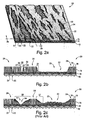
- FIGs. 2a-2b illustrates a flocked fabric 20 that is typical of the fabric that has been air embossed utilizing inventive air embossing systems and methods provided in accordance with the present disclosure.
- Air embossed features 22 are characterized by flattened or otherwise reoriented pile fibers. Adjacent to and separating embossed features 22 are unembossed portions 24 of the fabric surface, which are characterized by pile fibers 18 that extend essentially perpendicularly from adhesive layer 14.
- FIG. 2c illustrates a similar embossed pile fabric 30 typical of that produced according to conventional prior art air embossing systems and methods.
- a comparison of the inventive air embossed fabric 20 and the conventionally produced air embossed fabric 30 illustrates several important distinctions.
- the inventive air embossed fabrics can have embossed features wherein the smallest, most finely detailed embossed features have a characteristic dimension significantly less than that achievable with conventional systems and methods.
- embossed fabric 20 includes a smallest embossed feature 26 having a small characteristic dimension 28.
- a “characteristic dimension" of an embossed feature refers to the smallest cross-sectional dimension of the feature, as measured from a first edge 27 of an unembossed portion of pile layer 16 across the feature to a second edge 29 of another unembossed region on the opposite side of the feature.
- fabric 20 provided according to the present disclosure, has a significantly greater level of visual contrast between fibers in reoriented region 25 and the adjacent unembossed regions 24 of pile layer 16, when compared to fabric 30 produced according to conventional air embossing technology.
- the reoriented fibers in reoriented portion 25 are significantly more flattened onto the substrate in the inventive fabric 20.
- distance 31 separating the flattened fibers of reoriented portion 25 and the essentially perpendicular fibers of an adjacent unembossed portion 24 can be very small and significantly less than the equivalent distance 37 of fabric 30 typically achievable using conventional air embossing technology.
- air embossed fabrics produced by air embossing systems and methods as described herein can have an unprecedented level of fine detail and an unprecedented level of sharpness and visual contrast between embossed and unembossed portions of the pile fabric, yielding embossed patterns and visual effects previously unachievable by air embossing systems and producible only via utilization of more expensive roll embossing techniques.
- FIG. 3 illustrates a preferred method for forming and embossing a flocked pile fabric.
- the process for producing an embossed pile fabric for example similar to fabric 20 shown previously in FIG. 2a, can proceed as described below.
- Roll 102 of a substrate 12 can be conveyed, in the direction indicated by arrow 105, under tension from substrate roll 102 to take up roll 120 via conventional motor drive mechanisms for controllably driving one roll (i.e. take up roll 120) or both rolls.
- the fabric can be guided and supported along the path of the process via a series of support rollers 104.
- the fabric instead of, or in addition to, conveying the fabric via motor-driven rotation of the take up roll/substrate roll, the fabric may be moved through the system via a conventional conveying system, such as a belt or apron conveyor.
- An adhesive layer is then applied to substrate 12 by a conventional adhesive applicator 106, for example a roll coater, curtain coater, doctor blade, printing method etc.
- the adhesive is applied to the substrate by a doctor blade, although other methods such as printing, paint spraying and silk-screening may be used.
- an adhesive layer is applied to the entire upper surface of substrate 12.
- flocking chamber 108 which includes a pile applicator 110.
- a layer of flocking formed by a multiplicity of fibers 18 is applied to the adhesive. Conventionally, and as hereinafter described, this deposition may be achieved by conventional beater bar or electrostatic techniques in which the ends of the pile fibers 18 adhere substantially to the adhesive layer. Pile fibers 18, in preferred embodiments, are oriented essentially perpendicular to the adhesive layer.
- flocking chamber 108 may comprise an alternating current electrostatic flocking device having a variable frequency alternating electrostatic field that optimizes flocked fiber characteristics and processing efficiency, such as that described in commonly owned U.S. patent No. 5,108,777 to Laird.
- air embossing cylinder 112 After application of a pile layer, the flocked substrate 111 is passed under air embossing cylinder 112, which includes an air lance therein (shown and described in detail below) that is in fluid communication with pressurized air supply line 114.
- air embossing cylinder 112 typically comprises a cylindrical screen or stencil having perforations and solid areas therein.
- pressurized air from air supply line 114 is directed by the air lance through the apertures or perforations in the cylindrical screen or stencil of embossing cylinder 112, in order to form the embossed features within the pile layer of the fabric.
- An embossed pattern is formed by deflection of pile fibers 18 in the pile layer by air flowing through the apertures within the cylindrical screen or stencil of embossing cylinder 112.
- the air impinges upon pile fibers 18 and orients them in a direction that is dictated in part by the air velocity, direction of air flow, and size of the aperture in the stencil through which the air passes.
- those portions of the pile layer passing underneath apertures within the cylindrical stencil will become oriented to form the depressions in the embossed pattern, whereas those portions passing under solid areas of the stencil will not be subject to substantial air flow or reorientation of pile fibers 18 in the pile layer.
- the adhesive layer be in a wet, uncured state during the air embossing procedure, such that the pile fibers 18 are not rigidly held by the adhesive and are able to have their position and orientation changed by an impinging air flow.
- the velocity of the air flow impinging upon the pile layer should be sufficient to exert a force on pile fibers 18 in order to create a desired degree of reorientation of the fibers.
- the pile fabric After being embossed by embossing cylinder 112, the pile fabric is passed through a curing chamber 116 in order to cure the adhesive layer so that the embossed pattern becomes permanently set.
- Curing chamber 116 may be comprised of any conventional curing equipment that exposes the embossed, but uncured, pile fabric to radiation, or other means of temperature elevation, to effect curing of the adhesive layer.
- Typical curing chambers operate by exposing the flocked fabric to a source of radiation, such as infrared radiation or heat, or ultraviolet radiation.
- curing chamber 116 comprises a gas-fired air dryer, as is well known in the art, that exposes the flocked fabric to a flow of heated air to enable convective drying and curing of the adhesive.
- the embossed flocked fabric 118 exits the curing chamber and is wound onto take-up roll 120.
- the speed at which the fabric is conveyed through air embossing system 100 can vary depending on a number of operating factors, as apparent to those of ordinary skill in the art. For some typical embodiments, the speed would be in the range of about, for example, 25 to 150 ft/min.
- FIGs. 4a-4c show air embossing system 109 in greater detail.
- Air embossing system 109 comprises a modified version of a commercially available air embossing system (Aigle Equipment Model No. AP-1, Burgano Toninese, Italy).
- the inventive features described herein may be utilized with other commercial available air embossing systems or may be integrated into a custom built and designed air embossing system, as would be apparent to those of ordinary skill in the art.
- any particular dimensions, sizes, materials, etc. described below for the illustrated embodiments of the invention are purely exemplary and are based upon the physical and operational constraints of the particular illustrated embodiment of air embossing system 109.
- Embossing cylinder 112 includes a generally cylindrical central region, disposed above embossable surface 113 of unembossed fabric 111, comprising a generally cylindrical stencil 128, described in more detail below.
- Embossing cylinder 112 includes at each end thereof a reduced diameter stencil flange 130 (seen more clearly in FIG. 5) whereby it is attached to rotating bearings 132 of motorized drive unit 134.
- Stencil flanges 130 are attached to rotating bearings 132 utilizing stencil mounting clamps 136, which may be of any conventional design known to those of ordinary skill in the art.
- Motorized stencil drive unit 134 includes support structures 138 and 140 disposed on opposite sides of the width of fabric 111. At least one of support structures 138 and 140 includes therein a variable speed motor (not shown) which powers a conventional drive mechanism to rotate stencil 128 with respect to fabric 111.
- the drive mechanism for rotating the cylinder can be any suitable drive mechanism known in the art, including, but not limited to, belt-drive, gear-drive, friction and wheel-drive, inductive-drive, etc. mechanisms as apparent to those of ordinary skill in the art.
- the drive mechanism of the illustrated embodiment comprises a gear-drive mechanism in which a variable speed motor (not shown) within support structure 140 rotates a gear (not shown) which, in turn, is engaged with a circumferential gear (not shown) comprising an outer surface of rotating bearing 132 within support structure 138.
- variable speed embossing cylinder drive motor can be operated to rotate cylinder 112 in the direction of arrow 143 (i.e., in a direction opposite that of the motion 122 of fabric 111) or, more preferably, in the direction of arrow 142 (i.e., in the same direction as the direction 122 of fabric 111).
- embossing cylinder 112 is rotated in the direction of arrow 142 such that the speed of the surface of stencil 128 is essentially the same as the speed of fabric 111 passing under stencil 128.
- the rotational speed of apertures 144, within stencil 128 of embossing cylinder 112 is matched to the speed of fabric 111 passing underneath, resulting in embossed features 22 in the air embossed fabric 118 having an overall length, as measured in the direction of motion 122 which is essentially the same as the overall length of the aperture 144 in stencil 128, as measured along the direction of rotation 142, which forms the embossed feature.
- stencil 128 can be rotated, in some embodiments, at speeds that are different than the speed of the fabric passing under the stencil, in order to create a variety of embossed patterns on the fabric, which each have a different visual appearance, with a single, given stencil. For example, by rotating the stencil in direction 142 at a speed which is greater than that of the speed of the fabric passing under the stencil, the embossed features produced by air passing through apertures 144 are shortened as measured along a direction parallel to the direction of motion 122 of the fabric when compared to an equivalent embossed pattern produced by a stencil rotating at the same speed as the fabric.
- embossed features 122 can be relatively lengthened and the level of detail visually evident in the embossed feature can be increased when compared to features produced with a stencil rotated at the same speed as the speed of the fabric.
- the speed of the fabric differs from the speed of the rotating stencil by at least a factor of about 2, and in other embodiments differs from the speed of the fabric by at least a factor of about 4.
- Embossing cylinder 112 comprises a hollow cylinder having a centrally disposed stencil 128 defining an embossing region 146, which extends across the width of the fabric to be embossed.
- the embossing region is between about 54 inches and about 64 inches in length.
- the embossing cylinder 112, as illustrated, has a stencil region 128 having an outer circumference of about 635 mm (25 inches)
- the inner diameter of stencil region 128, in the illustrated embodiment is about 201.9 mm (7.95) inches, while the inner diameter of stencil flange 130 is about 139.7 mm (5.5 inches).
- Cylindrical stencil 128 can be conventionally formed from, for example, a cylindrical screen which has a series of solid, air impermeable regions 141 therein and a series of apertures 144 therein, which apertures permit air flow therethrough. Cylindrical stencil 128 can be formed in any manner conventionally used for forming such stencils. For example, in one embodiment, cylindrical stencil 128 can be formed using a well known lacquered screen ("Penta" screen) process, where a cylindrical screen, typically constructed from a metal such as nickel, is coated with a lacquer.
- the screen is first coated with an essentially uniform layer of lacquer, covered with a pattern template having regions that can block ultraviolet radiation, and exposed to ultraviolet radiation which tends to cure the lacquer.
- the regions of the screen beneath the pattern template regions that can block ultraviolet radiation will remain uncured after exposure and can be subsequently removed from the screen, thus leaving behind on the screen a lacquer coating, forming the stencil, having apertures therein with a pattern that is complementary to that of the pattern template.
- the stencil can be formed by coating a metal screen with a patterned metallic layer using a Galvano process well known in the art.
- cylindrical stencil 128 can be formed by directly covering a cylindrical screen with an air impermeable layer, such as a paper, plastic, or other air impervious layer, and then cutting out selected portions from the air impervious layer to form apertures 144. It is to be understood, of course, that regions corresponding to apertures 144 may be cut out of the air impervious layer prior to utilizing the layer to form cylindrical stencil 128.
- cylindrical stencil 128 may be formed from a stencil typically employed for use in rotary screen printing operations or by any other methods apparent to those of ordinary skill in the art for forming air embossing stencils.
- Apertures 144 in cylindrical stencil 128 result in the formation of embossed depressions 22 in embossed fabric 118 as air passes through the apertures and impinges upon fabric 111 as it passes under embossing cylinder 112.
- the embossed depressions 22 formed by apertures 144 can typically have a similar overall shape and orientation as the apertures in cylindrical stencil 128.
- cylindrical stencils e.g. 128, produced according to the above described methods, while preferably having a cylindrical shape which is essentially perfectly circular when sectioned in a plane perpendicular to the longitudinal axis of the stencil and while preferably having the longitudinal axis, which is centrally disposed within the stencil, being essentially co-linear to the longitudinal rotational axis of the embossing cylinder (e.g.
- run out refers to the difference between the distance separating the embossable surface of the fabric being embossed and the portion of the outer surface of the stencil positioned above and directly adjacent to the region of the fabric surface being embossed when the rotating stencil is in a rotational position such that the above-described separation distance is at its maximum value, and the distance separating the embossable surface of the fabric being embossed and the portion of the outer surface of the stencil positioned above and directly adjacent to the region of the fabric surface being embossed when the rotating stencil is in a rotational position in which the above-mentioned separation distance is at its minimum value.
- one aspect of the present invention involves stabilizing the rotation of the cylindrical stencil utilized for air embossing with one or more stencil stabilizers so that the stencil rotates substantially true about the rotational axis of the embossing cylinder so that there is a reduced variation in the distance separating the embossable surface of a fabric being embossed and the portion of the fabric-facing surface of the stencil directly adjacent to the embossable surface of the fabric during rotation of the stencil.
- support structures 138 and 140 also include mechanisms thereon for holding and positioning an air lance (shown and described in detail below), which air lance is configured and positioned to direct a stream of air through apertures 144 in stencil 128 and onto fabric 111 to produce embossed features 22 in embossed fabric 118.
- air lance shown and described in detail below
- FIGs. 4a and 4b in order to more clearly illustrate the air lance support and positioning mechanism, the air lance has been removed from the system and is not illustrated.
- the elongated air lance When assembled for operation, the elongated air lance is inserted into aperture 148 in rotating bearing 132 such that it is disposed within embossing cylinder 112, extends across the width of embossing cylinder 112, and is supported by air lance inlet cradle 150 and air lance outlet cradle 152 (shown more clearly in FIG. 4b) of system 109.
- Aperture 148 from which the inlet region of the air lance extends when installed in its operable configuration, has an internal diameter which is essentially equal to the internal diameter of stencil flange region 130 (i.e., about 5.5 inches as illustrated) of embossing cylinder 112.
- air lance inlet cradle region 154 is sized and shaped such that it is complementary to the size and shape of the inlet region of the air lance so that the inlet region of the air lance rests snuggly and securely within the air lance cradle region, when the system is in operation.
- Air lance inlet support arm 150 is pivotally attached to support structure 138 via spacer 156 and pivot bearing 158 so that the support arm can be pivoted up and down in the direction of arrows 160 in order to adjust the height of the air lance with respect to embossing cylinder 112 and in order to adjust the distance between the nozzle(s) in the air lance and the inside surface of stencil 128, as described in more detail below.
- Height adjustment of the air lance, supported by air lance inlet support arm 150, is effected by air lance inlet height adjuster 162.
- Height adjuster 162 comprises a main body 164 attached to the face of support structure 138 via mounting bracket 166.
- Height adjuster 162 further includes a reciprocating piston 168 connected to the air lance inlet support arm 150 via a nut 170 on a threaded end thereof.
- air lance inlet height adjuster 162 has a range of motion such that in a lower most position a nozzle of an air lance inserted into embossing cylinder 112 can contact the lowest portion of the internal surface of the embossing stencil, and an uppermost position providing a separation distance between the nozzle of the air lance and an internal surface of embossing stencil 128 that is at least as great as the maximum separation distance desired during operation the system.
- air lance inlet height adjuster 162 is pneumatically actuated via air line 172 to effect coarse up and down adjustment, and also includes a manually actuated fine height adjustment knob 174, which is utilized by an operator to make fine height adjustments.
- the height adjuster also, if desired, can include a scale 176, which can assist an operator to accurately and reproducibly position the inlet of the air lance.
- Air lance mounting shaft support arm 152 is similar in configuration to air lance inlet support arm 150 and is pivotally movable in order to adjust the height and position of the downstream end of the air lance via air lance downstream end height adjuster 178 which is essentially identical in design to inlet height adjuster 162.
- Height adjuster 162 and height adjuster 178 are adjusted to create an essentially uniform distance between the nozzle(s) of the air lance and an adjacent internal surface of embossing cylinder 112 that is essentially uniform across essentially the entire width of stencil region 128 of embossing cylinder 112.
- the height adjusters may be differentially adjusted such that some nozzles of the air lance are closer to the stencil than others, or some portions of a given nozzle provided by the air lance are closer to the internal surface of the stencil than other portions.
- the downstream ends of the illustrated air lances can include mounting shafts having outer diameters which are typically less than the outer diameters of the main body portions and inlet regions of the air lances.
- the mounting shaft of the air lance is supported and positioned by air lance mounting shaft support clamp 180 which is mounted to support arm 152 via bolt and nut fasteners 182.
- mounting shaft support clamp 180 is mounted within a slot 184 on a platform region 186 of support arm 152.
- mounting shaft support clamp 180 to be slidably movable in the direction of arrows 188, in order to adjust the lateral position of the downstream end of the air lance within embossing cylinder 112.
- the lateral position of the mounting shaft support clamp is adjusted so that the nozzle(s) of the air lance is positioned such that it is bisected by center line 190 of embossing cylinder 112.
- Mounting shaft support clamp 180 also includes an angular adjustment set screw and knob 192 which can be utilized to adjust the angular orientation of the air lance within embossing cylinder 112.
- Support clamp 180 also includes perpendicular alignment set screw 194, which is mateable with an alignment hole (see FIGs. 6-8) within the mounting shaft of the air lance.
- alignment set screw 194 When alignment set screw 194 is inserted into the alignment hole, it serves to fix the angular adjustment of the air lance so that the nozzle(s) is positioned to direct a stream of air essentially perpendicularly to the lowermost region of the internal surface of stencil 128 of embossing cylinder 112 (shown more clearly in FIG. 5 below).
- set screw 194 may be turned out so that it does not project into aperture 196 of mounting shaft support clamp 180, and the air lance may be positioned and secured utilizing angular adjustment set screw in knob 192 so as to position and secure the mounting shaft within aperture 196 at an orientation such that the nozzle(s) is not perpendicular and/or is not configured to direct an air stream essentially perpendicular to the lowermost internal surface of stencil 128 of embossing cylinder 112.
- the air lance may be positioned such that the air stream forms an angle of, for example, about 5 degrees to about 10 degrees with respect to center line 190.
- FIG. 4c illustrates a view of air embossing system 109 as seen by an observer positioned underneath fabric 111.
- system 109 includes a support surface 236 positioned directly beneath stencil 128 that is configured to support the underside of fabric 111 at a location where the adjacent embossable surface of the fabric is being impinged upon by an air stream emitted by the nozzle(s) of the air lance, when installed in the system during operation.
- the support surface may comprise a platform or other planar surface, it is preferred, as illustrated, that the support surface comprise a cylindrical, fabric support roller 104.
- fabric support roller 104 is mounted on roller mounting arms 198, which are supported by a roller support beam 200.
- roller mounting arms 198 may be configured so that the vertical position of fabric support roller 104 may be adjusted with respect to roller support beam 200, fabric 111 and stencil 128 in the direction of arrows 199.
- Fabric support roller 104 in preferred embodiments, is configured to be rotated, most preferably in a direction of motion 201 co-directional to fabric 111.
- fabric support roller 104 is driveably rotated via electric motor 202 and drive belt 204 located on motor support platform 203.
- fabric support roller 104 may be rotated by a wide variety of alternative mechanical means.
- a surface cleaning element 206 is provided in contact with an external surface 236 of fabric support roller 104.
- Surface cleaning element 206 serves to scrape off and remove any adhesive, pile fibers, or other debris which may collect on the surface 236 of fabric support roller 104, thus eliminating or reducing any buildup of debris under the surface of fabric 111 during operation, which buildup in prior art systems typically limits the length of time the system can be operated without shutdown and cleaning of the support surface.
- surface cleaning element 206 comprises a scraping blade positioned in contact with the outer cylindrical surface 236 of fabric support roller 104 along essentially the entire width of the fabric support roller positioned directly beneath stencil region 128 of embossing cylinder 112.
- the surface cleaning element is positioned to contact the support roller along substantially the entire length of the roller that is in contact with the underside of fabric 111.
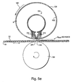
- FIG. 5a is a cross-sectional view of one embodiment of air embossing system 109.
- FIG. 5a illustrates a cross-sectional view of air embossing system 109 with one embodiment of an inventive air lance installed within the system and with certain details of the surrounding support structures not illustrated for clarity.
- Air lance 210 is somewhat similar in design to air lance 700 illustrated and discussed in greater detail in the context of FIGs. 8a-8g below. As discussed above, air lance 210, when installed in operable engagement with air embossing system 109, has an inlet region supported and positioned by air lance inlet support arm 150 and air lance inlet height adjuster 162, and has a mounting shaft at its downstream end that is supported and positioned by air lance mounting shaft support arm 152 and air lance mounting shaft height adjuster 178.
- Air lance 210 illustrates one embodiment for an air lance which enables the nozzle(s) of the air lance to be positioned in close proximity to or in direct contact with an internal surface of the stencil.
- Air lance 210 is shaped in the form of a tubular conduit and includes a main body portion 212 to which is attached a nozzle forming component 214.
- Nozzle forming component 214 includes at its end a nozzle 216 and is shaped and positioned to enable the nozzle to be placed in very close proximity to or in direct contact with a portion 218 of the inner surface 223 of stencil 128, which portion 218 of the inner surface faces and is adjacent to the nozzle and is disposed directly opposite the portion 233 of the outside surface of the stencil that is directly adjacent to fabric 111.
- a portion of an inner/outer surface of the stencil is "directly adjacent" to the fabric or the embossable surface of the fabric when such portion is positioned next to the fabric or the embossable surface at a distance, measured in a direction perpendicular to the fabric surface, less than the distance, measured in a direction perpendicular to the fabric surface, separating the fabric or embossable surface and any other portion of the inner/outer surface of the stencil.
- any separation distance(s) referred to herein between the fabric, or the embossable surface of the fabric, and the outer surface of the stencil, or the portion of the outer surface of the stencil directly adjacent the fabric or embossable surface of the fabric refer, unless otherwise indicated, to the perpendicular distance separating that portion of the outer surface of the cylinder that is positioned directly adjacent to the embossable surface of the fabric and that portion of the embossable surface of the fabric that is positioned directly adjacent thereto (i.e. the smallest separation distance between the outer surface of the cylindrical stencil and the embossable surface of the fabric measurable at any instant of time during rotation of the embossing cylinder).
- main body portion 212 preferably is essentially uniform in diameter along the entire length of the air lance through which air flows, when the air lance is in operation.
- the physical constraint of the air embossing system which prevents a nozzle formed directly in the side wall of a conventional air lance from being positioned in close proximity to or in contact with the inside of the stencil is due to the difference in internal diameter of stencil 128 and the smallest internal diameter 219 of stencil flange 130 and aperture 148 of the air embossing system.
- a distance 220 of about 1.2 inches exists between the inner surface 222 of aperture 148 and stencil flange 130 and the inner surface 223 of stencil 128.
- a nozzle formed in the side wall of the main body portion will be constrained by contact of the inlet portion of the air lance with surface 222, which contact will prevent the nozzle from being able to be positioned from the internal surface portion 218 of stencil 128 by a distance that is significantly less than distance 220.
- Nozzle forming component 214 which extends along a substantial fraction of the length of main body portion 212 but does not extend into the inlet portion of the main body, is able to bridge distance 220 to enable the nozzle 216 to be positioned as close to surface portion 218 of stencil 128 as desired or in contact with surface portion 218, if desired.
- Nozzle forming component 214 as described in more detail below in the context of FIGs. 8a-8g, preferably extends along the length of main body portion 212 across essentially the entire width of stencil 128 and fabric 111, but does not extend into regions of the main body portion adjacent to internal surface 222.
- main body portion 212 It is generally desirable to maximize the internal diameter of main body portion 212 in order to minimize any pressure drop along the length of air lance 210, when the system is in operation. It is also required to size nozzle forming component 214 so that it extends from the external surface of main body portion 212 by a distance that enables nozzle 216 in the nozzle forming component to be positioned at a desirable distance from surface portion 218 of stencil 128 and/or in contact with surface portion 218.
- nozzle forming component 214 is shaped and positioned to enable nozzle 216 to be separated from surface portion 218 by a distance, including in preferred embodiments a zero separation distance in contact with the inner surface, that is substantially less than the distance separating outlet opening 224 in main body portion 212, which outlet opening is in fluid communication with nozzle 216, and surface portion 218.
- “Substantially less than” when referring to the above discussed distance between nozzle 216 and surface portion 218 in comparison to the distance separating outlet opening 224 and surface portion 218 indicates that the distance separating nozzle 216 and surface portion 218 is no more than about 60% of the distance separating outlet opening 224 and surface portion 218, and may, in some preferred embodiments, be less than 1% of the distance separating the outlet opening in the main body of the air lance and surface portion 218 of the stencil.
- main body portion 212 of air lance 210 comprises an aluminum conduit having a wall thickness of about 3.175 mm (1/8 inch) and an outer diameter of about 101.6 mm (4 inches).
- air lance 210 may be constructed of a variety of other materials, for example, other metals, plastics, etc. and may have a wall thickness different than that above, which is selected to provide sufficient resistance to operating pressure for the chosen material, as would be apparent to those of ordinary skill in the art.
- the main body portion 212 includes an outlet opening 224 therein, which is in fluid communication with nozzle forming component 214.
- Outlet opening 224 may comprise a plurality of holes in the side wall of main body portion 212; however, in more preferred embodiments such as that illustrated, outlet opening 224 comprises an elongated slot extending along a substantial portion of the length of the main body portion, as illustrated more clearly in FIGs. 8a - 8g.
- Main body portion 212 may also be stabilized against internal pressure by including one or more internal support struts 226 along its length, which can be welded or otherwise attached to main body portion 212 and can extend across outlet slot 224 in order to resist expansion of main body portion 212 when the air lance is in operation.
- the inlet of air lance 210 is attached to an air supply 114, as shown above in FIG.
- Typical operating pressures within air lance 210 can range from about 25.4 mm H 2 O (1 inch H 2 O) to about 2540 mm H 2 O (100 inches H 2 O).
- Nozzle forming component 214 may be formed of any suitable material, as would be apparent to those of ordinary skill in the art, and, in preferred embodiments is formed of a rigid metal. Nozzle forming component 214 spans outlet slot 224 of main body portion 212 and includes an upper curved surface 225 shaped to conform to the contour of the outer surface of main body portion 212. Nozzle forming component 214 may be attached to main body portion 212 by any variety of means apparent to those of ordinary skill in the art. In the illustrated embodiment, nozzle forming component 214 is removably attached to main body portion 212 via a plurality of bolts 228 positioned along the length of the nozzle forming component on opposite sides of outlet slot 224.
- Nozzle forming component 214 includes an internal chamber 230 therein which extends along the length of the nozzle forming component coextensive with nozzle 216.
- Nozzle 216 can comprise a plurality of individual holes or ports within the lower surface of nozzle forming component 214; however, in order to avoid artifacts caused by the air impermeable spaces between nozzles comprising individual apertures or orifices, in preferred embodiments, nozzle 216 comprises an elongated rectangular slit extending along a substantial fraction of the length of nozzle forming component 214 and across the width of stencil 128 and the embossable width of fabric 111, when installed in the system.
- nozzle slit 216 extends along the length of nozzle forming component 214 so that it is co-extensive with outlet slot 224 in main body portion 212 and is aligned directly beneath and parallel with the outlet slot.
- nozzle forming component 214 extends away from main body portion 212 so that nozzle 216 is separated from outlet opening 224 by a distance of about 1.25 inches, which is sufficient to more than span the entirety of distance 220 separating surface portion 218 and surface 222, when the air lance is positioned in an operable configuration within the air embossing system.
- the illustrated combination for example, of a 4 inch external diameter main body portion 212 and a nozzle forming component 214 that extends away from the main body portion by a distance by about 1.25 inches, results in an overall effective diameter 232 of air lance 210 that is just sufficient to clear smallest diameter 219 of stencil flange 130 and aperture 148 of the air embossing system.
- the length of air stream 231 between its source at nozzle 216 and surface portion 218 is accordingly reduced, and the amount of dispersion of the air stream is significantly reduced or essentially eliminated, resulting in the ability to achieve much finer levels of detail and an improved appearance of the embossed features of embossed fabric 118.
- the close proximity of nozzle 216 to surface portion 218 of stencil 128, or contact between the nozzle and the surface combined with the ability of nozzle forming component 214 to effectively redirect airflow from a direction essentially parallel to longitudinal axis 320 of air lance 210 to a direction substantially perpendicular to the longitudinal axis can enable air stream 231 to be directed in a direction that is much more perpendicular to the surface of fabric 111 than is achievable in conventional air lance designs.
- the position of air lance 210 and the distance separating nozzle 216 from surface portion 218 of stencil 128 can be adjusted by an operator as desired via manipulation of height adjusters 162 and 178.
- the angular orientation of nozzle 216 with respect to center line 190 may be adjusted via angular adjustment set screw and knob 192 and perpendicular alignment set screw 194 (see in FIG. 4b).
- air lance 210 is positioned such that its alignment slot in its mounting shaft (see e.g. FIGs.
- nozzle 216 is positioned along the center line 190 of stencil 128 so as to direct air stream 231 essentially perpendicular to surface portion 218 and the embossable surface 113 of fabric 111.
- nozzle 216 is positioned such that it is separated from surface portion 218 of stencil 128 during operation by a distance not exceeding about 14.05 mm (0.75 inch), resulting in air stream 231 having a length between the nozzle 216 and surface portion 218 not exceeding about 19.05 mm (0.75 inch).
- the distance separating nozzle 216 and surface portion 218 does not exceed about 12.7 mm (0.5 inch), in other embodiments does not exceed about 6.35 mm (0.25 inch), in yet other embodiments does not exceed about 2.54 mm (0.1 inch), in other embodiments does not exceed about 1.27 mm (0.05 inch), in yet other embodiments does not exceed about 0.635 mm (0.025 inch), in other embodiments does not exceed about 0.318 mm (0.0125 inch) and in yet other embodiments does not exceed about 0.254 mm (0.01 inch).
- the nozzle 216 is placed in direct contact with surface portion 218 resulting in a zero separation distance.
- fabric-facing surface portion 233 of stencil 128 is positioned from the embossable surface of pile layer 16 by a distance not exceeding about 0.254 mm (0.01 inch), in other embodiments by a distance not exceeding 0.127 mm (0.005 inch) and yet in other embodiments by a distance not exceeding about 0.025 mm (0.001 inch).
- the distance between surface portion 233 and pile layer 16 be very small but without surface portion 233 actually making physical contact with pile layer 16, which would tend to distort the pile air and create undesirable visual artifacts.
- variation in the distance separating fabric surface 113 and surface portion 233 during rotation owing to irregularities in the shape or centering of stencil 128 causing "run out” can seriously impair or make impossible the achievement of the above mentioned desired separation distances without incurring artifacts due to contact of the stencil with the fabric.
- the disclosure also describes means for stabilizing the rotation of the stencil to overcome or reduce this problem. Such means are discussed in much greater detail below.
- support surface 236 of fabric support roller 104 be positioned such that its upper most surface portion 238 is aligned with center line 190 such that surface portion 238 is positioned directed beneath and spaced apart from nozzle 216 such that air stream 231 exiting the nozzle is directed to impinge upon fabric 111 at a location 241 where the fabric is adjacent to and in contact with support surface 236.
- This configuration prevents the fabric from being pushed away from the embossing surface of stencil 128 by air stream 231 and maintains the desired distance between stencil 128 and pile layer 16 of embossable fabric 111.
- a “characteristic orifice dimension" of a nozzle refers to the smallest cross-sectional dimension of the nozzle.
- the characteristic orifice dimension 240 comprises the width of the elongated slit forming nozzle 216.
- the characteristic dimension of each nozzle would be the diameter of the circular hole forming the nozzle.
- the characteristic dimension can be determined by measuring the smallest cross-sectional dimension of the particular shape comprising the nozzle (e.g., for a nozzle comprising an ellipse, the characteristic orifice dimension would comprise the length of the minor axis of the ellipse).
- the characteristic orifice dimension of the nozzles of air lances provided according to the invention is less than about 5.08 mm (0.2 inch).
- the characteristic orifice dimension of the nozzle does not exceed about 2.54 mm (0.1 inch), in other embodiments does not exceed about 1.27 mm (0.05 inch), in yet other embodiments does not exceed about 0.254 mm (0.01 inch), in other embodiments does not exceed about 0.127 mm (0.005 inch), and in yet other embodiments does not exceed about 0.0254 mm (0.001 inch).
- the total amount of open area of the nozzles, through which the air stream passes is a much smaller fraction of the cross-sectional internal area of the main body portion of the air lance supplying air to the nozzle.
- the inventive air lances having nozzles with small characteristic orifice dimensions, generally can have a much higher fraction of the total resistance to air flow provided by the nozzle(s) than is typical for conventional prior art air lance designs.
- the total open area provided by the nozzle(s) of the air lances provided by the invention does not exceed about 15% of the internal cross-sectional area of the main body portion of the air lance.
- the nozzle area does not exceed about 7.5%, in other embodiments does not exceed about 1.5%, and in yet other embodiments does not exceed about 0.1% of the total open cross-sectional area of the main body portion of the air lance.
- the pressure drop along the length of the air lance can be substantially reduced, and the air flow emitted from the nozzle(s) along the length of the air lance can be much more evenly distributed than in conventional air lance designs.
- the air flow velocity through the nozzle(s) of the air lance can be substantially constant along the portion of the length of the air lance along which the nozzle(s) is positioned. This uniformity of air flow velocity emitted from the air lance along its length can result in a high degree of uniformity in the embossed pattern across essentially the entire width of fabric 111.
- sufficient air flow is supplied so that the velocity of air exiting the nozzle(s) of the air lance is at least about 76.2 m/sec (15,000 feet per minute), in other embodiments at least about 101.6 m/sec (20,000 feet per minute) and in yet other embodiments at least about 127 m/sec (25,000 feet per minute).
- Such air flow velocities are substantially higher than those employed or achievable by typical prior art air embossing systems and enable the inventive system to produce extremely finely detailed embossed patterns.
- the air flow velocity through the nozzle(s) of the air lances can be easily determined by an operator of the system based upon the total open area of the nozzle(s), a measured inlet pressure of the air supply to the air lance, and performance charts typically supplied by the manufacture of the air blower utilized to supply air to the air embossing system. Such measurements and determinations are routine for those of ordinary skill in the art.
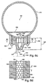
- FIG. 5b illustrates a first embodiment for providing stencil stabilizers for reducing variations in the distance separating embossable surface 113 of fabric 111 and the portion 233 of the fabric-facing surface of the stencil that is directly adjacent to the embossable surface of the fabric during rotation of the stencil.
- Stencil 128 in the embodiment illustrated in FIG. 5b comprises a stencil characterized by "run out,” as previously discussed, making the maintenance of a consistent distance separating surface 113 of the fabric and portion 233 of the outer surface of the stencil during rotation of the stencil and operation of the system essentially impossible. Without some form of stencil stabilization, such as that shown in FIG.
- the separation between the portion 233 of the outer surface of the stencil and surface 113 of the fabric directly adjacent portion 233 would vary during rotation of the stencil by an amount essentially equal to the degree of "run out" inherent in the stencil, which can be as much as 0.254 mm (0.1 inch) or more.
- the stencil stabilizers comprise end surfaces 250 and 251 of nozzle forming component 214, positioned on the upstream and downstream sides of nozzle 216 respectively.
- surfaces 250 and 251 are coated with an anti-friction material, for example polytetrafluoroethylene (PTFE), or other friction reducing coating known to those of ordinary skill in the art, in order to prevent wear and damage to inner surface 223 of stencil 128 during use.
- PTFE polytetrafluoroethylene
- nozzle 216 acts as stencil stabilizers upon being brought into direct contact with inner surface 223 of stencil 128. Also, in the configuration illustrated in FIG. 5b, nozzle 216 is separated from inner surface portion 218 of stencil 128 by a zero separation distance (i.e., is in direct contact with surface portion 218), which is also desirable, in many embodiments, for increasing the level of definition of the embossed pattern formed on surface 113 of fabric 111 by decreasing, or essentially eliminating, the degree of dispersion of the air stream emitted from nozzle 216 prior to contact with inner surface portion 218 of stencil 128.
- a zero separation distance i.e., is in direct contact with surface portion 218
- the stencil stabilizer(s) provided by the air embossing system is brought into contact with and forced against inner surface 223 of stencil 128 to an extent sufficient to apply a force to the stencil during operation of the system that is sufficient to reduce variations in the distance separating embossable surface 113 of fabric 111 at position 241 and portion 233 of the outer surface of the stencil directly adjacent to the embossable surface of the fabric during rotation of the stencil, and in even more preferred embodiments is sufficient to essentially eliminate variations in the above-mentioned separation distance.
- the stencil stabilizer(s) is brought into contact with the inner surface of the stencil and is forced against the inner surface to a degree sufficient to create a tension in the stencil, which tension is sufficient to reduce, and preferably eliminate the degree of "run out” of the stencil and create a consistent separation distance between portion 233 of the fabric-facing surface of stencil 128 and embossable surface 113 of the fabric during air embossing.
- the tension created in stencil 128 due to contact of the stencil stabilizers with the inner surface of the stencil can be sufficient to distort the unstressed shape of the stencil during rotation.
- the unstressed shape of stencil 128 illustrated in FIG. 5b is shown by phantom lines 252, which shape is distorted due to the tension created in stencil 218 during operation of the system.
- FIGs. 5d-5f the function of stencil stabilization provided according to some aspects of the invention is illustrated for a system including a stencil 128 having a somewhat irregular, elliptical shape, and displaying a substantial degree of "run out” during rotation.
- FIGs. 5d and 5e illustrate operation of the system configured to provide a desired separation distance ( d max ) between the embossable surface of the fabric and the portion of the external surface of the stencil directly adjacent to the embossable surface without a force applied to the stencil by a stencil stabilizer, and FIG.
- 5f illustrates operation of the same system as configured to provide a desired separation distance ( d max ) between the embossable surface of the fabric and the portion of the external surface of the stencil directly adjacent to the embossable surface including stabilization of the stencil during rotation.
- stencil stabilizer surfaces 250 and 251 of nozzle forming component 214 are not positioned in contact with inner surface 223 of stencil 128, and thus no force is applied to stencil 128 to stabilize its rotation.
- location (A) of stencil 128 is at the 12 o'clock position where the elliptically shaped stencil is rotationally positioned such that the separation distance between surface 113 of fabric 111 at position 241 and the portion 233 of the outer, fabric-facing surface of stencil 128 directly adjacent to position 241 is at its minimum value ( d min (no force) ).
- the degree of "run out" of stencil 128 is sufficient to cause the fabric-facing surface of the stencil to directly contact fabric 111 when the stencil is in the position illustrated in FIG.
- FIG. 5e illustrates the configuration of the system as illustrated in FIG 5d, except after stencil 128 has rotated in the direction of arrow 142 one quarter turn.
- the above-described separation distance between fabric surface 113 and portion 233 of the fabric-facing surface of stencil 128 is at its maximum value ( d max (no force) ).
- the "run out" of stencil 128 is defined as the difference d max (no force) - d min (no force) .
- FIG. 5f illustrates the system of FIGs. 5d and 5e, also configured to provide a desired separation distance ( d max ) between the embossable surface of the fabric and the portion of the external surface of the stencil directly adjacent to the embossable surface, except configured so that the stencil 128 and air lance 210 are positioned within the system such that stencil stabilizing surfaces 250 and 251 of nozzle forming component 214 are in contact with the inner surface 223 of stencil 128 so as to apply a force to the stencil during operation of the system sufficient to reduce, and preferably eliminate, variations in the above-mentioned separation distance between the outer surface of stencil 128 and surface 113 of fabric 111 during rotation of the stencil.
- d max desired separation distance
- Surfaces 250 and 251 comprising stencil stabilizers are preferably in contact with the inner surface of stencil 128 at at least one rotational position of stencil 128, and in particularly preferred embodiments, the stencil stabilizers provided by the system are in contact with the internal surface of stencil 128 continuously throughout its rotation.
- the maximum distance ( d max (force) ) separating embossable surface 113 at position 241 of fabric 111 from portion 233 of the outer surface of stencil 128 directly adjacent to the embossable surface of the fabric will be less than the maximum separation distance of the stencil equivalently configured within the system and positioned with respect to fabric 111 as illustrated in FIG 5f, except without having a force applied to the stencil by the stencil stabilizer(s) ( d max (no force) ) (i.e. with the longitudinal axes of stencil 128 and roller 104 equivalently spaced but without surfaces 250 and 251 being engaged in contact with inner surface 223 of the stencil).
- the stencil stabilizers are forced against the inner surface of the stencil so that variations in the separation distance between the portion of the outer surface of the stencil directly adjacent the fabric and the embossable surface of the fabric are essentially eliminated during rotation (i.e., d max (force) is essentially equal to d min (force) during rotation of the stencil).
- d max (no force) The extent to which the maximum above-mentioned separation distance between the stencil and the fabric with no force applied ( d max (no force) ) will exceed the maximum separation distance when the system is configured to apply a stabilizing force to the cylindrical stencil ( d max (force) ), as illustrated in FIG. 5f, will depend on the degree of "run out" of stencil 128 (i.e., d max (no force) - d min (no force) ). In typical embodiments, d max (no force) can exceed d max (force) by at least about 0.001 in., in other embodiments by at least about 0.01 in., in other embodiments by at least 0.05 in., and in yet other embodiments by at least about 0.1 in.
- d max (no force) - d max (force) is selected to essentially equal or slightly exceed d max (no force) minus d min (no force), in order to essentially eliminate "run out” and variation in the distance separating the embossable surface of the fabric and the portion of the outer surface of the stencil directly adjacent to the embossable surface during rotation of the stencil.
- the method for stabilizing the rotation of stencil 128, as illustrated in FIG 5f comprises first positioning a portion of the fabric-facing surface of the stencil directly adjacent to embossable surface 113 of fabric 111 at a first distance from the embossable surface of the fabric and then positioning the stencil stabilizers (surfaces 250 and 251) with respect to the inner surface of stencil 128 such that the stencil stabilizers are in contact with the inner surface of stencil 128.
- the stencil stabilizers are positioned within stencil 128 such that at least a portion thereof is in contact with the inner surface of stencil 128 during the entire rotation thereof and is pressed against the inside surface of the stencil with sufficient force during rotation to essentially eliminate "run out.”
- stencil 128 is installed into the system and rotationally positioned, as illustrated above in FIG. 5d, so that the distance separating embossable surface 113 of fabric 111 and that portion of the fabric-facing surface of stencil 128 directly adjacent thereto is minimized (i.e., d min (no force) ).
- the vertical position of roller 104 and/or stencil 128 is then adjusted such that d min (no force) essentially equals or slightly exceeds the desired separation distance between the portion of the fabric-facing surface of stencil 128 directly adjacent to the fabric and embossable surface 113 of the fabric.
- the stencil stabilizers are then subsequently positioned into engaging contact with inner surface 223 of stencil 128 (e.g., by positioning air lance 210 such that stencil stabilizing surfaces 250 and 251 are in engaging contact with the inner surface of stencil 128) and forced against the inner surface of the stencil, if necessary, until the portion of the fabric-facing surface of stencil 128 directly adjacent to the fabric and embossable surface 113 of the fabric are separated by the desired separation distance.
- FIG. 5c illustrates one preferred embodiment for providing a stencil stabilizer constructed to be positioned in contact with an inner surface of the stencil during operation of the system, while also providing a non-zero separation distance between nozzle 216 and inner surface 223 of stencil 128.
- surface 253 of the upstream side of nozzle forming component 214 forms the stencil stabilizer in contact with inner surface 223 of stencil 128 during rotation.
- surface 253 is preferably coated with a friction-reducing material to prevent wear and damage to stencil 128 during use.
- nozzle forming component 214 is formed from an upstream 256 and a downstream 257 subcomponent, each positioned on a separate side of opening 224 in conduit 212.
- Nozzle forming component 214 is formed by mounting separable components 256 and 257 on opposite sides of outlet opening 224 such that they are positioned adjacent and separated from each other on conduit 212 so that the distance between adjacent facing surfaces 258 and 259 of the separable components defines a slit forming nozzle 216.
- upstream separable component 256 of nozzle forming component 214 is mounted to conduit 212 with a series of spacers or shims 260 positioned between the outer surface of the conduit and contoured upper surface 225 of component 256.
- spacers or shims 260 is selected to be equal to the desired separation distance between the nozzle 216 and the inner surface portion 218 of the stencil.
- component 256 may simply be manufactured such that it extends away from opening 224 and conduit 212 by a greater distance than subcomponent 257, or, in yet other embodiments, one or more ridges, projections, etc., may be attached to or formed on subcomponent 256 such that they extend beyond nozzle 216 to contact the inner surface 223 of stencil 128.
- nozzle forming component 214 may be formed of a single, monolithic unit, instead of being formed as two separable components, as illustrated in FIG. 5c.
- downstream component 257 may be shimmed, etc., such that it extends away from opening 224 by a distance exceeding the maximum distance by which subcomponent 256 extends away from opening 224.
- surface 261 would comprise the stencil stabilizing surface, which surface is positioned downstream of nozzle 216. It is preferred, however, that a stencil stabilizer be positioned to contact the inner surface of the stencil upstream of the nozzle, as illustrated in FIG. 5c, in order to prevent buildup of debris and other material which tends to clog the nozzle.
- the stabilizer is constructed and positioned on the air lance to contact the inner surface of the stencil, when the air lance is configured in the system for operation, and is further constructed and positioned on the air lance so that the portion of the stencil stabilizer making contact with the inner surface of the stencil during operation is separated from the longitudinal central axis (e.g., axis 320 as shown in FIG. 5c) of the conduit by a distance that exceeds the distance separating the nozzle of the air lance from the longitudinal central axis of the conduit.
- the longitudinal central axis e.g., axis 320 as shown in FIG. 5c
- stencil stabilizing surface 253 is separated from longitudinal central axis 320 by a distance that exceeds the distance separating nozzle 216 from longitudinal central axis 320.
- a desired separation distance between nozzle 216 and inner surface portion 218 of stencil 128 is enabled by positioning upstream separable component 256 of nozzle forming component 214 such that the maximum separation distance separating the upstream component from longitudinal central axis 320 (i.e., the distance separating surface 253 from longitudinal axis 320) exceeds the maximum distance separating downstream separable component 257 from longitudinal central axis 320 (i.e., the distance separating surface 261 from longitudinal axis 320) by an amount essentially equal to the desired distance separating nozzle 216 from inner surface portion 218 of stencil 128.
- FIG. 6a illustrates an alternative embodiment of an air lance.
- Air lance 300 as shown in FIG. 6a, has a nozzle region 302 of main body portion 304 positioned so that it is facing the observer.
- FIG. 6b shows air lance 300 in a side view.
- Air lance 300 comprises a conduit having a main body portion 304 and includes an inlet opening 306 and a threaded inlet connector 308, allowing attachment of the air lance to air supply line 114 of the air embossing system when it is in operation.
- Main body portion 304 is essentially constant in diameter along its entire length.
- Main body portion 304 includes an inlet region 310 upstream of nozzle region 302 and may, optionally, include a small end region 312 downstream of nozzle region 302 and upstream of sealed end 314 of the main body portion.
- air lance 300 may, instead of having a single inlet opening for attachment to the air supply, have each of its ends open for fluid communication and attachable to an air supply.
- mounting shaft 316 Affixed to downstream end 314 of main body portion 304 is mounting shaft 316 including an alignment slot 318 (seen most clearly in FIG. 6b), which mounting shaft typically has a diameter that is smaller than the diameter of main body portion 304.
- inlet region 310 When mounted in an operable configuration within air embossing system 109, inlet region 310 is disposed upon air lance inlet cradle 154 (see FIG. 4a) such that at least inlet connector 308 extends beyond air lance inlet support 150, so as to be easily connectable to air supply line 114.
- Air lance 300 is disposed within embossing cylinder 112 and extends across the entire width of the embossing cylinder so that mounting shaft 316 is disposed within air lance mounting tube support clamp 180 of the air embossing system (see FIG. 4b), when the air lance is configured for operation.
- alignment slot 318 is configured to be engageable, when the air lance is in the above-described mounting position, with perpendicular alignment set screw 194, thus allowing the perpendicularly aligned position of the nozzle to be easily ascertained and securely maintained during operation.
- Nozzle region 302 of air lance 300 extends along main body portion 304 in a direction essentially parallel to longitudinal axis 320 of the air lance so that it is located within, and is essentially coextensive with, the width of stencil region 128 of embossing cylinder 112, when the air lance is installed in an operable configuration. Accordingly, nozzle region 302 is also configured to extend across essentially the entire width of the embossable surface 113 fabric 111, when in operation.
- nozzle region 302 is about 1371.6 mm (54 inches) to about 1625.6 mm (64 inches) in length
- inlet region 310 is about 609.6 mm (24 inches) to about 711.2 mm (28 inches) in length
- end region 312 is about 25.4 mm (1 inch) to about 101.6 mm (4 inches) in length
- mounting shaft 316 is about 330.2 mm (13 inches) to about 381 mm (15 inches) in length and is about 50.8 mm (2 inches) to about 76.2 mm (3 inches) in outer diameter.
- Nozzle region 302 includes therein a plurality of individual nozzles 324, which, in the illustrated embodiment comprise a plurality of circular holes within main body portion 304.
- nozzles 324 comprise holes bored directly into the side wall of main body portion 304; however, in alternative embodiments, nozzles 324 may be formed in a separable plate element, which is attachable by screws or other fasteners to main body portion 304.
- the holes 324 comprising the nozzles may be arranged of positioned differently within nozzle region 302 than that shown. For example, in one alternative embodiment, the nozzles may be arranged in a single row within the nozzle region.
- nozzle region 302 in the illustrated embodiment, includes nozzles 324 comprising of a plurality of individual holes separated by regions 325 of main body portion 304, which regions 325 are impermeable to air flow, it is preferred that nozzle region 302 be separated from inner surface 218 of stencil 128 (see FIG. 5) by at least about 19.05 mm (0.75 inch).
- the outer diameter of main body portion 304 is essentially constant (typically about 101.6 mm (4 inches) to about 133.35 mm (5 1 ⁇ 4 inches)), as previously discussed in the context of FIG. 5, it is not possible to position nozzles 324 any closer to inner surface 218 of stencil 128 than distance 120 (e.g., about 30.48 mm (1.2 in), as illustrated).
- main body portion 304 preferably includes flaps 326 installed on each side of nozzle region 302.
- the flaps are flexible, in some embodiments, and thus they do not tend to prevent insertion of the air lance through the flanged region 130 of the embossing cylinder 112, and so that after insertion into the embossing cylinder, they extend downward from main body portion 304 by a distance preferably approximately equal to the distance separating nozzles 324 from the internal surface of the stencil region of the embossing cylinder.
- one or both of flaps 326 can be replaced by a rigid component extending away from main body portion 304, forming a doctor blade positionable in contact with the inner surface of the air embossing stencil, when the air lance is positioned for operation.
- the overall, effective outermost diameter of the air lance-stabilizer combination cannot exceed distance 219 as illustrated in FIG. 4d.
- the rigid doctor blade(s) forming one or both of components 326 and providing stencil stabilization can be separable from main body component 304 and interchanged with other rigid components of different size or can be positioned on body 304 at varying distances (as measured along the circumference of body 304) from the nozzles, in order to change the separation distance between the nozzles and the inner surface of the stencil, when the air lance is positioned for operation with the stencil stabilizer(s) in contact with the inner surface of the stencil.
- nozzles 324 have a characteristic dimension, characterized by the diameter of the holes comprising nozzles 324, that does not exceed about 0.2 inch, as was discussed above in the context of air lance 210 illustrated in FIG. 5a.
- the characteristic dimension of nozzles 324 does not exceed about 2.54 mm (0.1 inch), in other embodiments does not exceed about 1.27 mm (0.05 inch), in yet other embodiments does. not exceed about 0.254 mm (0.01 inch), in other embodiments does not exceed about 0.127 mm (0.005 inch) and in yet other preferred embodiments does not exceed about 0.0254 mm (0.001 inch).
- Air lance 300 is shown in cross section in FIG. 6c.
- Nozzle region 302 is shown magnified in figure insert 328 of FIG. 6c.
- FIG. 6c illustrates one preferred embodiment for providing nozzles 324 having a characteristic nozzle length 330 which exceeds the characteristic orifice dimension 332 of the nozzle.
- characteristic nozzle length 330 is essentially equal to the wall thickness of main body portion 304.
- the diameter of nozzles 324 be no greater than, and preferably less than, the wall thickness of main body portion 304.
- the "characteristic nozzle length,” as used herein in the context of the air lances provided according to the invention, refers to the maximum dimension of the nozzle as measured in a direction that is essentially parallel to the overall direction of air flow within the nozzle (i.e., in a direction that is typically essentially perpendicular to the longitudinal axis of the air lance).
- the air lances can significantly reduce the proportion of the air stream that is emitted from the nozzle in a diagonal direction with respect to the inner surface of the stencil, the surface of the fabric, and the longitudinal axis of the air lance.
- the nozzles are in the form of circular holes having characteristic nozzle lengths approximately equal to the diameter of the holes forming the nozzle, it is apparent that essentially the entire stream of air directed towards the inner surface of the stencil through each nozzle will be directed through the nozzle at an angle of at least about 45 degrees with respect to the longitudinal axis of the air lance, when the system is in operation. Any component of the air stream forming an angle less than 45 degrees with respect to the longitudinal axis will impinge upon a side wall (e.g., walls 333 shown in FIG. 6c) and will be deflected towards the surface of the stencil at an angle with respect to the longitudinal axis of the air lance of at least about 45 degrees.
- a side wall e.g., walls 333 shown in FIG. 6c
- the characteristic length 332 of nozzles 324 exceeds the characteristic orifice diameter 332 by at least a factor of about 2, in more preferred embodiments by at least a factor of about 3, and in the most preferred embodiments, by at least a factor of about 4.
- FIG. 6d and FIG. 6e show cross sectional views of an alternative embodiment of air lance 300 that includes a plurality of air redirecting elements 340 that are shaped and positioned to intercept and deflect the air flow within main body portion 304 so that a greater fraction of the air flow is directed essentially perpendicular to longitudinal axis 320 and to the embossable surface 113 of fabric 111, when the air embossing system is in operation.
- air directing elements 340 preferably intercept and direct the air flow so that essentially all of the air flow exits from nozzles 324 toward the fabric in a direction making an angle of at least about 45 degrees with respect to longitudinal axis 320 of the air lance.
- Air redirecting elements 340 comprise a series of baffles that may be formed of a wide variety of materials and may comprise a variety of structures able to deflect and redirect air flow.
- An "air redirecting element”, “air flow redirecting element,” or “baffle” as used herein refers broadly to any element positioned within an air lance, which is shaped, positioned, and configured such that at least a portion of the flow of air supplied to the air lance impinges upon and is redirected by the element from an initial air flow direction forming an angle of less than about 45 degrees with respect to the longitudinal axis of the air lance to a subsequent air flow direction forming an angle greater than about 45 degrees with respect to the longitudinal axis of the air lance.
- air flow redirecting elements 340 comprise a plurality of tubular inserts positioned within outlet openings 341 of main body portion 304.
- Air redirecting elements 340 have an outer diameter that is equal to or slightly less than the diameter of outlet openings 341, such that they may fit snuggly and securely within outlet openings 341, when installed as shown in FIG. 6d.
- Air redirecting elements 340 can, in some embodiments, be press fit into outlet openings 341 or, for improved stability, may be welded to main body portion 304, once they are inserted into outlet openings 341.
- air redirecting elements 340 may be welded, or otherwise attached within main body portion 304 adjacent and in fluid communication with outlet openings 341, without actually being inserted into the outlet openings.
- Nozzles 324 as illustrated, have a characteristic orifice dimension 342 essentially equal to the internal diameter of air directing elements 340 and have a characteristic nozzle length 344 essentially equal to the length of air directing elements 340, as measured in a direction perpendicular to longitudinal axis 320 of the air lance.
- air directing elements 340 instead of being press fit within outlet openings 341 of main body portion 304, may have an inner diameter equal to or greater than the diameter of outlet openings 341 and may be attached to an inner surface of main body portion 304 above outlet openings 341, as described above, such that the characteristic nozzle length comprises the sum of the wall thickness of main body portion 304 plus the length of an air redirecting element 340, as measured along a direction perpendicular to longitudinal axis 320.
- a substantial fraction of both (i.e., at least about 50%) of the characteristic length of the nozzle be comprised of the length of the air redirecting element, as measured in a direction essentially perpendicular to the longitudinal axis of the main body.
- the length 344 of air redirecting elements 340 exceeds characteristic orifice dimension 342 of nozzles 324 by a factor of at least about 2, more preferably a factor of at least about 3, and most preferably by a factor of at least about 4.
- FIGs. 6f and 6g illustrate a cross-sectional view of another alternative embodiment of air lance 300 including a main body portion 304 including therein a single, monolithic air redirecting element 350.
- a "monolithic" air redirecting element refers to an air redirecting element having a plurality of surfaces for redirecting or deflecting air, wherein the surfaces are formed within a single, undivided piece of material, or comprise a plurality of physically distinct elements that are interconnected together so as to form a continuous structure.
- Air redirecting element 350 is preferably positioned within main body portion 304 and attached to an internal surface of the main body portion by welded attachments, or other means of fastening, as would be apparent to those of ordinary skill in the art.
- Air redirecting element 350 has an overall width and length sufficient to essentially completely cover and be coextensive with nozzle region 302 of air lance 300. Air redirecting element 350 performs an essentially equivalent function as that previously described for air redirecting elements 340 in the context of FIGs. 6d and 6e above. Air redirecting element 350 can comprise a wire or fabric mesh, screen, grate, or any other suitable structure, as would be apparent to those of ordinary skill in the art. Air redirecting element 350, as illustrated in FIG. 6g, can comprise a grate-like structure having a plurality of cells 352, which form air flow channels that are oriented essentially perpendicularly to longitudinal axis 320 of the air lance.
- Cells 352 are separated one from another by a series of walls of structure 350 forming dividers 354.
- Distance 356, is the characteristic dimension of channels 352.
- the "characteristic dimension" of a channel in a monolithic air redirecting element, as used herein, is defined as the largest cross-sectional dimension of the channel as measured along a direction essentially parallel to the longitudinal axis of the air lance.
- the monolithic baffle 350 illustrated in FIGs. 6f and 6g has channels 352 comprising a plurality of square conduits arranged in a grid pattern.
- the monolithic air redirecting element may have channels comprising a plurality of cells having cross-sectional shapes other than square.
- monolithic air redirecting element 350 comprises a honeycomb-like structure, described in more detail below in the context of FIG. 9, having a plurality of hexagonally shaped cells arranged in a honeycomb-like pattern.
- the height 358 of air redirecting element 350 exceeds characteristic dimension 356 by a factor of at least about 2, more preferably by a factor of at least about 3, and most preferably by a factor of at least about 4.
- Air redirecting element 350 when it is constructed and positioned as shown in FIGs. 6f and 6g functions to increase the fraction of air flow through nozzles 324 that is directed essentially perpendicularly to the longitudinal axis 320 of the air lance and essentially perpendicularly to the surface of the fabric being embossed, when the air embossing system is in operation.
- the monolithic air redirecting elements provided in the embodiment illustrated in FIGs. 6f and 6g, and in other embodiments of the air lances described below, increase the fractional amount the stream of air directed through apertures or openings in the stencil of the air embossing system that is oriented in a direction essentially perpendicular to the embossable surface of the fabric being embossed, when the air lance is in operation, when compared to the fractional amount of a stream of air directed through the openings in the stencil essentially perpendicular to the embossable surface of the fabric by an essentially equivalent air lance, but without the air redirecting element included therein.
- Air lance 500 illustrated in FIGS. 7a-7e represents an alternative embodiment for providing certain of the benefits of air lance 220, discussed above in the context of FIG. 5a, and air lance 700, discussed below in the context of FIGS. 8a-8g.
- air lance 500 is configured to provide a nozzle that can be positioned in close proximity to the internal surface of an embossing stencil and in close proximity to the surface of an embossable fabric.
- Air lance 500 when installed in air embossing system 109 similarly to the installation shown previously for air lance 220 in FIG. 5a, can be positioned with respect to interior surface portion 218 of stencil 128 (see FIG.
- Nozzle 502 may be positioned at distances with respect to surface portion 218 that are similar to the preferred distances separating surface 218 and nozzle 216 of air lance 210 described above in the context of FIG. 5a, or the nozzle may be positioned in direct contact with inner surface portion 218 of the stencil at a zero separation distance in some embodiments.
- Air lance 500 comprises a main body portion 504 including, in preferred embodiments, a single, slit-shaped nozzle 502 extending along a substantial fraction of the length of main body portion 504 and defining nozzle region 506.
- the air lance may include a plurality of nozzles comprising individual holes instead of a single, slit-shaped nozzle.
- the nozzle region preferably extends across essentially the entire width of embossing cylinder stencil region 128 and embossable surface 113 of fabric 111, when the air lance is positioned within air embossing system 109 for operation.
- Nozzle 502 in preferred embodiments, has a characteristic orifice dimension, defined by width 508 of the slit, that is less than about 5.08 mm (0.2 inch) and preferably falls within the preferred range discussed above for nozzle 216 of air lance 210.
- slit width 508 is essentially constant along the entire length of nozzle region 506.
- slit 502 may be tapered so that slit width 508 changes along the length of the nozzle.
- slit 502 may be wider at the end of the nozzle nearest offset inlet tube 510 than at the end nearest offset mounting shaft 512. Such a configuration, especially for nozzles having relatively large characteristic orifice dimensions, may improve the uniformity of air flow velocity along the length of nozzle region 506.
- FIG. 7b a side view of air lance 500 shows that inlet tube 510 and mounting shaft 512 have centers that are offset with respect to longitudinal axis 320 of the air lance.
- Inlet tube 510 also has a smaller diameter than main body portion 504 of air lance 500.
- Providing a reduced diameter inlet tube, which is offset with respect to longitudinal axis 320, enables the provision of an overhang region 514, which enables nozzle 502 to be positioned within embossing cylinder 112 so that it is able to be placed in a desirably close proximity to or in contact with the internal surface portion 218 of stencil 128 (see FIGs. 5a and 5b).
- air lance 500 can be configured, as in the illustrated embodiment, with a main body portion 504 having an outside diameter of about 133.35 mm (51 ⁇ 4 inches) (or somewhat smaller than 133.35 mm (51 ⁇ 4 inches) so as to permit clearance of optional stencil stabilizers 550 when in their fully collapsed configuration as explained below), and having an offset inlet tube, as illustrated, having an outside diameter of no more than about 71.12 mm (2.8 inches).
- This configuration provides an overhang distance 514 of at least about 30.48 mm (1.2 inches) sufficient to completely traverse distance 220 shown above in FIG. 5a.
- inlet tube 510 should be of sufficient length so that upstream surface 518 of main body portion 504 is positioned within embossing cylinder 112 so that it is completely contained within the large internal diameter portion of the embossing cylinder, when configured for operation.
- air lance inlet support arm 150 of air embossing system 109 should be configured so that air lance inlet cradle 154 is shaped and sized to conform to the smaller size of inlet tube 510 of air lance 500.
- FIGs. 7c, 7d, and 7e A cross-sectional view of a preferred embodiment of air lance 500 is shown in FIGs. 7c, 7d, and 7e.
- main body portion 504 is stabilized by one or more support struts 226, as described above in the context of air lance 210 in FIG. 5a.
- the lance also includes a monolithic air redirecting element or baffle 520 that can be essentially similar in configuration and function to air redirecting element 350 described above in the context of FIGs. 6f and 6g.
- nozzle 502 is positioned in close proximity to the internal surface of the embossing stencil (e.g., at distances of less than about 19.05 mm (0.75 inch) or in direct contact with the inner surface of the stencil, it is preferred that the thickness of the walls or dividers 522 of structure 520 separating each of the cells or channels 524 be less than the characteristic orifice dimension of nozzle 502. It has been found, in the context of the present invention, that if wall thickness 522 exceeds the characteristic orifice dimension of nozzle 502 that undesirable, visually apparent artifacts may be created in the embossed pattern of a fabric embossed using the air lance.
- the thickness of walls 522 of structure 520 be less than, and preferably substantially less than, the characteristic orifice dimension of nozzle 502.
- the thickness of walls 522 is preferably minimized such that it is as small as possible, while maintaining the structural integrity of baffle 520 in operation.
- the thickness of the walls may not exceed about 0.051 mm (0.002 inch)
- the wall thickness of walls forming a monolithic baffle comprising an aluminum honeycomb-like structure may be as small as about 0.0254 mm (0.001 inch) or less.
- Air lance 500 illustrated in FIG. 7a-7e also includes a plurality of optional stencil stabilizer components 550 attached to the conduit comprising main body portion 504 of the air lance.
- stencil stabilizing components 550 are positioned on both the upstream side and the downstream side of nozzle 502 on main body portion 504.
- the structure and position of stencil stabilizer components 550 is most clearly illustrated in FIGs. 7a, 7b, and 7e.
- stencil stabilizing components 550 include a base portion 553, which is attached to main body portion 504, and further include extending away from base portion 553 and main body portion 504 stencil contacting elements 554, aligned essentially parallel to the longitudinal axis 320 of air lance 500.
- Stencil contacting elements 554 of stencil stabilizer components 550 are preferably coated, as described previously, with a friction-reducing coating to prevent damage to the interior surface of the stencil during rotation of the stencil.
- Stencil contacting elements 554 are supported by and spaced from cylindrical bases 553 via shafts 555.
- base components 553 are sized and positioned such that end surfaces 559 do not extend substantially beyond line 556 lying within the plane of nozzle 502.
- stencil contacting elements 554 and connecting shafts 555 are biased by spring 557 within mounting portion 553 of stencil stabilizers 550 tending to force stencil contacting elements 554 in a direction extending away from main body 504. Accordingly, stencil stabilizers 550 are partially collapsible, by applying a force to stencil contacting elements 554 directed towards the main body of the air lance, enabling the distance separating nozzle 502 from the inner surface of an embossing stencil into which air lance 500 is mounted for operation to be adjustable, while maintaining stencil contacting elements 554 in contact with the inner surface of the embossing stencil.
- Spring actuated stencil stabilizers 550 thus enable air lance 500 to be positioned within embossing cylinder 112 during operation of the air embossing system 109 so that nozzle 502 can be separated from the inner surface portion 218 of the embossing stencil 128 by any distance less than or equal to distance 558, while maintaining stencil contacting elements 554 in contact with the inner surface of the embossing stencil during rotation of the stencil (see FIG.
- the distance separating nozzle 502 and the inner.surface portion 218 of the stencil can be varied from essentially zero to distance 558 while providing a stabilizing force to the inner surface of the stencil sufficient to reduce variations in the distance separating the embossable surface of the fabric and the portion of the fabric-facing surface of the stencil directly adjacent thereto during rotation of the stencil.
- Stencil contacting elements 554 are separated from longitudinal axis 320 of air lance 500 by a distance that is adjustable via applying a force to air lance 500 tending to move nozzle 502 closer to the inner surface of the embossing stencil when the air lance is mounted in the system so that stencil contacting elements 554 are in contact with the inner surface of the stencil.
- the level of force applied to the inner surface 223 of stencil 128 will therefore be inversely proportional to the distance separating nozzle 502 from inner surface portion 218 of the stencil, when stencil contacting elements 554 are in contact with the inner surface of the stencil.
- spring 557 may be replaced by any other element able to apply a restoring force tending to extend stencil contacting elements 554 from main body component 504 of the air lance 500 when compressed, which are known to those of ordinary skill in the art, for example, including, but not limited to, air bladders, various elastomeric components, etc.
- springs 557 may be replaced by hydraulic or pneumatic pistons, mechanical displacement actuators, or other such components known in the art, which are able to controllably extend, retract, and position stencil contacting elements 554 at a desired, predetermined distance with respect to main body component 504 of air lance 500.
- the degree of extension of stencil contacting elements 554 could be manually and/or automatically adjustable during operation to also provide a desired predetermined level of force applied to the embossing stencil created by elements 554 in contact with the inner surface of the embossing stencil for any desired separation distance.
- the level of force for such embodiments, can, therefore, be adjusted, independently of the separation distance between the nozzle and he inner surface of the stencil, to a selected desired value for any desired separation distance between nozzle 502 and the inner surface of the embossing stencil.
- FIGs. 8a-8g illustrate a preferred embodiment of an air lance 700 essentially similar in configuration to air lance 210 described previously in the context of FIG. 5a-5b, except including a nozzle forming component 702 configured to contain one or more air redirecting elements or baffles therein and including an optional stencil stabilizer 900 comprising a collapsible, hinged doctor blade thereon.
- Elements which are essentially identical to those described previously for air lance 210 are labeled in FIGs. 8a-8g using the same figure labels.
- components essentially equivalent to or similar to those illustrated and discussed in the context of air lance 300 shown in FIGs. 6a-6g are also labeled with the same figure labels as those used in FIGs. 6a-6g.
- nozzle forming component 702 includes, machined therein, a nozzle slit 216, which extends along the majority of its length except for regions 703 and 705 at its upstream and downstream ends respectively.
- Nozzle forming component 702 preferably is sized so that it projects beyond an outermost surface 707 (see FIG. 8b) of main body portion 212 by a distance 709 that is equal to or greater than distance 220 shown and discussed above in the context of FIG. 5a, thus, enabling nozzle 216 to be positioned as close to surface portion 218 of stencil 128 as is desired during operation or in contact with surface portion 218 of stencil 128, if desired.
- Nozzle slit 216 can be formed in nozzle forming component 702 by a variety of conventional machining methods, as would be apparent to those of ordinary skill in the art, including, but not limited to, cutting with a blade, water jet cutting, laser cutting, etc.
- nozzle forming component 702 instead of being formed of a unitary, monolithic structure having slit 216 machined therein, may instead comprise two separable components, each separable component being mounted on opposite sides of outlet opening 224 of main body portion 212 (see FIG.
- air lance 700 includes a nozzle region 704, having a length defined by the length of nozzle 216, which nozzle region extends across essentially the entire width of stencil 128 and embossable surface 113 of embossable fabric 111, when air lance 700 is positioned within air embossing system 109 for operation.
- FIGs. 8c and 8e present cross-sectional views of air lance 700 illustrating one preferred embodiment for providing an air redirecting element 800 within nozzle forming component 702.
- Nozzle forming component 702 includes a hollow chamber 708 therein for containing air directing element 800 and further includes, downstream of hollow chamber 708, a tapered chamber 710, which serves to further direct and focus air flow within the nozzle forming component toward slit nozzle 216.
- Main body portion 212 includes an outlet opening 224 comprising an elongated slot disposed along the length of the main body portion essentially coextensive with and parallel to slit nozzle 216.
- Hollow chamber 708 and tapered chamber 710 extend along the length of nozzle forming component 702 so that they are essentially coextensive with slit nozzle 216 and elongated slot 224 in main body portion 212.
- Air redirecting element 800 in the illustrated embodiment, comprises a monolithic aluminum honeycomb-like structure, shown in more detail in FIG. 9 and discussed above in the context of FIGs. 6 and 7. As shown most clearly in FIG. 8d and FIGs. 9a and 9b, air redirecting element 800 comprises a plurality of hexagonally shaped cells 802 with a characteristic dimension 804 and a height 806. In one embodiment, air redirecting element 800 comprises an aluminum honeycomb structure including a plurality of hexagonally shaped cells 802 each having a characteristic dimension of about 3.175 mm (1/8 inch) and a height of about 12.7 mm (1 ⁇ 2 inch).
- the thickness of the walls 808 of the structure separating cells 802 is less than the characteristic orifice dimension of nozzle 216.
- the thickness of walls 808 is about 0.051 mm (0.002 inch), and in another illustrative embodiment, the thickness is about 0.0254 mm (0.001 inch).
- hollow chamber 708 preferably is sized and shaped to snuggly accommodate monolithic air redirecting element 800 in order to prevent vibration and motion of the air redirecting element during operation of the air lance.
- air redirecting element 800 may be welded, or otherwise affixed to one or more internal surfaces of hollow chamber 708 in order to further prevent motion of the element during operation.
- hollow chamber 708 is preferably located within nozzle forming component 706 so that air redirecting element 800 is positioned as far upstream of nozzle 216 as possible.
- Positioning air redirecting element 800 as far upstream as possible from nozzle 216 further acts to reduce potential artifacts within an embossed pattern of a fabric, which artifacts may be due to the presence of walls 808 separating the cells 802 of the air redirecting element.
- Air redirecting element 800 is preferably installed in hollow chamber 708 so that channels 802 formed by the cells of the structure of the monolithic air redirecting element are aligned so that they are essentially perpendicular to longitudinal axis 320 of main body portion 212.
- air redirecting element 800 serves to redirect and deflect air flow within main body portion 212 so that a greater fraction of air flow emitted from nozzle 216 is directed essentially perpendicularly to longitudinal axis 320 and embossable surface 113 of fabric 111, as compared to that emitted from an essentially equivalent air lance but without air redirecting component 800 installed therein.
- Stencil stabilizer 900 constructed and positioned on the air lance to apply a force to the embossing stencil of the air embossing system in which the air lance is installed during operation of the system in order to reduce variations in the distance separating the embossable surface of the fabric being embossed and the portion of the fabric-facing surface of the stencil that is directly adjacent thereto during rotation of the stencil.
- Stencil stabilizer 900 comprises a spring-biased articulated arm assemblies 902 connected at its stencil-contacting end to a doctor blade 904 which, in the illustrated embodiment, comprises an elongated rod, bar, blade, etc.
- Doctor blade 904 is preferably coated, at least on its stencil-contacting surface 906, with a material, such as PTFE, effective to reduce friction caused by contact and relative motion between the stencil-contacting surface 906 and the inner surface of the stencil during operation.
- a material such as PTFE
- FIG. 8e which most clearly shows the articulated arm assemblies 902 of stencil stabilizer 900.
- three such articulated arm assemblies are included to support and position the doctor blade 904; however, more or fewer such structures may be utilized depending on the overall length of doctor blade 904, the force with which doctor blade is engaged with the inner surface of the stencil during operation, etc., as would be apparent to those of ordinary skill in the art.
- Stencil stabilizer 900 can be connected to air lance 700 via attachment to nozzle forming component 702.
- articulated arm assembly 902 includes a first extension arm 908 connected to nozzle forming component 702 via flange 910 and bolt 228.
- Arm 908 is pivotally connected at its other end 912 to arm 914, which includes, or is connected to, at end 916 to doctor blade 904.
- a spring 918 is connected to both arm 908 and 914 and is constructed to provide a biasing force tending to pivot arm 914 with respect to 908 in the direction of arrow 920 thus, similar to stencil stabilizers 550 illustrated in FIGs.
- stencil stabilizer 900 is constructed so that, when air lance 700 is installed in an operable configuration in air embossing system 109 the distance separating the nozzle 216 from the inner surface portion 218 of the stencil 128 in which the air lance is installed can be adjustable, while maintaining doctor blade 904 in contact with the inner surface of the stencil to provide a force thereon to stabilize the rotation of the stencil.
- the level of force applied to the inner surface of the stencil is inversely proportional to the distance separating nozzle 216 from the inner surface portion 218 of the stencil due to the increase in restoring force created by spring 918 upon the movement of doctor blade 904 closer to longitudinal axis 320 of the air lance in the direction of arrow 922.
- Stencil stabilizer 900 is configured to contact the inner surface of the embossing stencil in which air lance 700 is installed during operation with nozzle 216 positioned at any desired separation distance from the inner surface portion 218 of the stencil, ranging from a zero separation distance with nozzle 216 in direct contact with inner surface portion 218 of the stencil (i.e., when stencil stabilizer 900 is in a collapsed configuration) to a maximum separation distance 924 with stencil stabilizer 900 in its fully extended position.
- stencil stabilizer 900 can be positioned in its fully collapsed configuration to minimize the overall diameter of the air lance with the stencil stabilizer attached thereto.
- arm 908 may be further articulated to include an additional pivot point(s) therein enabling assembly 902 to be rotated towards main body portion 212 such that pivot point 912 lies against or in close proximity to surface 926 of nozzle forming component 702.
- a spring is illustrated as providing a biasing force
- alternative embodiments as discussed above in the context of stencil stabilizers 550, a variety of other known mechanisms and/or materials for providing a restoring force tending to extend doctor blade 904 may be utilized.
- biasing means 918 can, in alternative embodiments, be replaced with a mechanical, pneumatic, hydraulic, etc., actuating mechanism configured to controllably adjust the position of doctor blade 904 with respect to longitudinal axis 320 and nozzle 216 in order to controllably adjust the level of force applied to the inner surface of the embossing stencil when the air lance is configured for operation in the system and positioned with nozzle 216 separated from the inner surface of the stencil by any desired distance ranging from contact of the nozzle with the inner surface of the stencil to a maximum separation distance (e.g., distance 924 shown in FIG. 8e) dictated by the overall structure of the stencil stabilizer and range of motion of the controllable positioning actuator.
- a maximum separation distance e.g., distance 924 shown in FIG. 8e
- Nozzle forming component includes a hollow chamber 758 therein that contains a plurality of air redirecting elements 760 comprising a series of baffling vanes disposed along essentially the entire length of chamber 758 and spaced apart from each other at regular intervals defined by distance 762. Vanes 760 are preferably oriented within chamber 758 so that an air deflecting surface 764 of each vane is essentially perpendicular to longitudinal axis 320 of main body 212. As shown in FIG.
- nozzle forming component 756 preferably includes a plurality of spaced grooves 766 in side wall 768 of chamber 758 for positioning and securing the edges of vanes 760 therein.
- Grooves 766 should have a width that is essentially equal to or slightly less than thickness 770 of vanes 760, such that when inserted into grooves 766 vanes 760 are essentially immobilized during operation of the air lance.
- nozzle forming component 756 may include a chamber not including vane-mounting grooves therein, and the vanes may instead be secured to the side wall of the chamber by welding or other affixing means, as would be apparent to those of ordinary skill in the art.
- thickness 770 of each of vanes 760 is less than the characteristic orifice dimension of slit nozzle 216. In one illustrative . embodiment, thickness 770 of vanes 760 is less than about 0.02 inch, and in another illustrative embodiment is less than about 0.01 inch.
- each vane 760 exceeds the distance 762 between each of vane 760 by a factor of at least about 2, and, in more preferred embodiments exceeds the distance by a factor of at least about 3, and in the most preferred embodiments exceeds the distance by a factor of at least about 4. While several embodiments of air redirecting elements for redirecting air flowing within an air lance have been illustrated herein, those of ordinary skill in the art will readily envision a variety of other means and structures for providing air redirecting elements to perform the functions described herein, and each of such variations or modifications are deemed to be within the scope of the present invention.
- FIGs. 10a and 10b illustrate an alternative embodiment of air embossing system 109 including a stencil stabilizer 1002, which is not connected to any air lance installed in the system during operation.
- a doctor blade 1002 (seen most clearly in the insert of FIG. 10a) is supported at its ends by air lance inlet support arm 150 and air lance mounting shaft support arm 152.
- Stencil stabilizer 1002 comprises a first end 1006 supported in aperture 1000 of air lance inlet support arm 150.
- Stencil stabilizer 1002 includes a second end 1008, which is inserted at its end in aperture 1004 of mounting shaft support arm 152. End pieces 1006 and 1008 of stencil stabilizer 1002 are connected via connecting pieces 1010 and 1012 to doctor blade 1014, whose outer surface 1015 is positioned in contact with the inner surface of embossing stencil 128 during operation to stabilize the rotation of the stencil. End pieces 1006 and 1008 have a length that is sufficient to span reduced diameter stencil flange region 130 on each end of rotating embossing cylinder 112.
- Connecting arms 1010 and 1012 preferably have a length that is selected to enable doctor blade 1014 to come into direct contact with the inner surface of stencil 128 when inlet support arm 150 and outlet support arm 152 are positioned to provide a desirable spacing between the nozzle of the air lance and the inner surface of embossing stencil 128.
- apertures 1000 and 1004 may comprise elongated slots enabling the vertical position of stencil stabilizer 1002 to be adjusted as indicated by arrows 1016.
- Such a configuration enables the vertical position of doctor blade 1014 to be adjustable to accommodate a range of vertical positions of inlet support arm 150 and outlet support arm 152 corresponding to a variety of desired separation distances between the nozzle of an installed air lance and the inner surface of stencil 128 during operation.
- stencil stabilizer 1002 can be biased by a spring or other mechanism in a direction 1018 tending to engage doctor blade 1014 with the inner surface of stencil 128.
- the vertical position of stencil stabilizer 1002 can be manually and/or automatically controlled by including a mechanical, hydraulic, etc., actuating mechanism able to controllably adjust the vertical position of stencil stabilizer 1002 with respect to support arms 150 and 152 during operation of the system.
- each of the previously illustrated stencil stabilizing mechanisms is that essentially no portion of any of the previously described stencil stabilizers intercepts or obstructs the stream of air emitted from the nozzle of the air lance during rotation of the stencil and operation of the system. Accordingly, the stencil stabilizers previously described do not tend to create undesired artifacts in the embossed pattern due to obstruction of the fabric-embossing air stream. Such interception of the air stream by the stencil stabilizers is avoided in the previously described embodiments by constructing and positioning the stencil stabilizer with respect to embossing stencil 128 such that the stencil stabilizer does not rotate during rotation of the stencil.
- the stencil stabilizer can be configured so that it rotates with the stencil and crosses the path of the air stream emitted from the nozzle of the air lance installed in the system.
- the stencil stabilizers can comprise one or more substantially rigid bars attached to the inner surface of stencil 128, or positioned in engaging contact with the inner surface of stencil 128, and extending either longitudinally between reduced diameter stencil flanges 130 or extending circumferentially around at least a portion of the inner circumference of stencil 128.
- stencil stabilizers can be configured to apply a force to the outside, fabric facing surface of the stencil to stabilization instead of, or in addition to, applying a force to the inside surface of the stencil as shown and discussed previously.
- certain alternative embodiments of a stencil stabilizer within the scope of the invention, can be configured to apply a force to the stencil for stabilization of its rotation as discussed above without contacting any surface of the stencil.
- Such alternative stencil stabilizers can, for example, create a tension within the stencil by applying a force to one or both ends of the cylindrical stencil either directed inwardly, towards the center point of the stencil, so as to slightly reduce the unstressed length of the stencil and create a hoop stress in the stencil by expansion of its unstressed circumference, or directed outwardly, away from the center point of the stencil, so as to slightly increase the unstressed length of the stencil and create tension in the stencil by reduction of its unstressed circumference.
- a force may be applied to the stencil by a stencil stabilizer(s) without contact between the stabilizers) and the inner or outer surface of the stencil by configuring the stabilizer(s) to apply a force to the stencil by utilizing a magnetic and/or electric field.
- stencil stabilizing components for stabilizing the rotation of the air embossing stencil during rotation to reduce variations in the distance separating the embossable surface of the fabric being air embossed and the portion of the fabric-facing surface of the stencil directly adjacent thereto during rotation of the stencil have been illustrated herein, those of ordinary skill in the art will readily envision a variety of other means and structures for providing stencil stabilizers to perform the functions described herein, and each of such variations or modifications are deemed to be within the scope of the present invention.
Landscapes
- Engineering & Computer Science (AREA)
- Textile Engineering (AREA)
- Treatment Of Fiber Materials (AREA)
- Shaping Of Tube Ends By Bending Or Straightening (AREA)
- Application Of Or Painting With Fluid Materials (AREA)
Claims (34)
- System zum Prägen einer Oberfläche eines prägbaren Gewebes mittels Gas, mit einer zylindrischen Schablone (128), die eine Innenseite (223) und eine dem Gewebe zugewandte Seite (233) aufweist, und einer Lanze (210, 300, 500, 700), die mindestens eine Düse (216) enthält, die in Bezug auf die Innenseite der Schablone (128) so darauf angeordnet ist, dass sie einen Strom des Gases ausstoßen kann, so dass das Gas gelenkt wird, mindestens eine Öffnung (144) in der Schablone (112) zu durchlaufen und, wenn das System in Betrieb ist, auf die prägbare Oberfläche des Gewebes aufzutreffen, wobei der Gasstrom genug Geschwindigkeit und Bündelung hat, um in einem Muster, das einem die mindestens eine Öffnung in der Schablone kennzeichnenden Muster entspricht, sichtbare Prägevertiefungen in der Oberfläche des Gewebes zu erzeugen, dadurch gekennzeichnet, dass mindestens ein Schablonenstabilisator (250, 251, 550, 900) betreibbar ist, während des Betriebs des Systems eine Kraft auf die Innenseite der Schablone (128) auszuüben, um Veränderungen in einer Distanz, die die prägbare Oberfläche des Gewebes und einen direkt daran angrenzenden Abschnitt der dem Gewebe zugewandten Seite der Schablone (128) trennt, während der Drehung der Schablone (128) zu vermindern.
- System nach Anspruch 1, bei dem der mindestens eine Schablonenstabilisator (250, 251) betreibbar ist, während des Betriebs des Systems eine Kraft auf die Schablone (128) auszuüben, um Veränderungen in einer Distanz, die die prägbare Oberfläche des Gewebes und einen direkt daran angrenzenden Abschnitt der dem Gewebe zugewandten Seite (233) der Schablone (128) trennt, während der Drehung der Schablone (128) im Wesentlichen zu beseitigen.
- System nach Anspruch 1 oder 2, bei dem mindestens ein Abschnitt des oder jedes Schablonenstabilisators (250, 251) in Kontakt mit der Innenseite (223) der Schablone (128) angeordnet ist.
- System nach Anspruch 3, bei dem mindestens ein Abschnitt des oder jedes Schablonenstabilisators (250, 251) während der Gesamtheit ihrer Drehung in im Wesentlichen kontinuierlichem Kontakt mit der Innenseite (223) der Schablone (128) ist.
- System nach Anspruch 3 oder Anspruch 4, bei dem die von dem mindestens einen Schablonenstabilisator (250, 251) auf die Schablone (128) ausgeübte Kraft ausreicht, um eine Spannung in der Schablone (128) zu erzeugen.
- System nach Anspruch 5, bei dem die von dem mindestens einen Schablonenstabilisator (250, 251) auf die Schablone ausgeübte Kraft ausreicht, um die Gestalt der Schablone (128) während mindestens eines Abschnitts der Drehung der Schablone (128) zu verformen.
- System nach irgendeinem vorhergehenden Anspruch, bei dem kein Abschnitt des Schablonenstabilisators (250, 251) einen aus der Düse (216) ausgestoßenen Gasstrom während der Drehung der Schablone (128) aufhält.
- System nach irgendeinem vorhergehenden Anspruch, bei dem sich der Schablonenstabilisator (250, 251) während der Drehung der Schablone (128) nicht dreht.
- System nach irgendeinem vorhergehenden Anspruch, bei dem der Schablonenstabilisator (250, 251) mit der Lanze (210, 700) verbunden ist.
- System nach Anspruch 9, bei dem der Schablonenstabilisator (250, 251) mindestens einen Abschnitt einer düsenbildenden Komponente (214) der Lanze (210, 700) aufweist.
- System nach Anspruch 9 oder Anspruch 10, bei dem mindestens ein Abschnitt des Schabtonenstabitisators (250, 251) in einer Nulltrennungsdistanz in Kontakt mit der Innenseite (223) der Schablone (128) angeordnet ist und bei dem eine Distanz, die die Düse (216) von der Innenseite (223) der Schablone (128) trennt, gleich der Nulltrennungsdistanz ist oder sie übersteigt.
- System nach Anspruch 11, bei dem die Distanz, die die Düse (216) von der Innenseite (223) der Schablone (128) trennt, einstellbar ist.
- System nach Anspruch 12, bei dem das Niveau der auf die Innenseite (223) der Schablone (128) ausgeübten Kraft umgekehrt proportional zu der Distanz ist, die die Düse (216) von der Innenseite (223) der Schablone (128) trennt.
- System nach irgendeinem der Ansprüche 9 bis 13, bei dem mindestens ein Abschnitt des Schablonenstabilisators (250, 251) die Innenseite (223) der Schablone (128) an einem stromaufwärts von der Düse (216) liegenden Ort berührt.
- System nach irgendeinem der Ansprüche 1 bis 13, bei dem das System mindestens zwei Schablonenstabilisatoren (250, 251) enthält.
- System nach Anspruch 15, bei dem mindestens ein Abschnitt eines ersten Schablonenstabilisators (250) die Innenseite (223) der Schablone (128) an einem stromaufwärts von der Düse (216) liegenden Ort berührt und bei dem mindestens ein Abschnitt eines zweiten Schablonenstabilisators (251) die Innenseite (223) der Schablone (128) an einem stromabwärts von der Düse (216) liegenden Ort berührt.
- System nach Anspruch 1, bei dem eine maximale erste Distanz, die die prägbare Oberfläche des Gewebes von einem direkt daran angrenzenden Abschnitt der dem Gewebe zugewandten Seite (233) der Schablone (128) trennt, ohne die vom Schablonenstabilisator (250, 251) auf die Schablone (128) ausgeübte Kraft eine maximale zweite Distanz übersteigt, die die prägbare Oberfläche des Gewebes von dem direkt daran angrenzenden Abschnitt der dem Gewebe zugewandten Seite (233) der Schablone (128) trennt, wenn das System für Betrieb mit der vom Schablonenstabilisator (250, 251) auf die Schablone (128) ausgeübten Kraft eingerichtet ist.
- System nach Anspruch 17, bei dem die erste Distanz die zweite Distanz um mindestens 0,0254 mm (0,001 Inch) übersteigt.
- System nach Anspruch 18, bei dem die erste Distanz die zweite Distanz um mindestens 0,127 mm (0,005 Inch) übersteigt.
- System nach Anspruch 19, bei dem die erste Distanz die zweite Distanz um mindestens 0,254 mm (0,01 Inch) übersteigt.
- System nach Anspruch 20, bei dem die erste Distanz die zweite Distanz um mindestens 1,27 mm (0,05 Inch) übersteigt.
- System nach Anspruch 21, bei dem die erste Distanz die zweite Distanz um mindestens 2,54 mm (0,1 Inch) übersteigt.
- System nach irgendeinem vorhergehenden Anspruch, bei dem die Düse (216) so angeordnet ist, dass mindestens ein Abschnitt davon die Innenseite (223) der Schablone (128) berührt, wenn das System in Betrieb ist.
- System nach Anspruch 23, bei dem ein die Düse (216) bildender Abschnitt der Lanze (210, 300, 500, 700), der die Innenseite (223) der Schablone (128) berührt, eine Kraft auf die Innenseite (223) der Schablone (128) ausübt, die ausreicht, um Veränderungen in einer Distanz, die die prägbare Oberfläche des Gewebes und einen direkt daran angrenzenden Abschnitt der dem Gewebe zugewandten Seite (233) der Schablone (128) trennt, zu vermindern.
- System nach Anspruch 4, bei dem der die Düse (216) bildende Abschnitt der Luftlanze (210, 300, 500, 700), der die Innenseite (223) der Schablone (128) berührt, eine Kraft auf die Innenseite (223) der Schablone (128) ausübt, die ausreicht, um Veränderungen in einer Distanz, die die prägbare Oberfläche des Gewebes und einen direkt daran angrenzenden Abschnitt der dem Gewebe zugewandten Seite (233) der Schablone (128) trennt, im Wesentlichen zu beseitigen.
- System nach Anspruch 9, bei dem sich der mindestens eine Schablonenstabilisator (128) von der Lanze (210, 300, 500, 700) her erstreckt.
- System nach Anspruch 10, bei dem die düsenbildende Komponente (214) eine erste trennbare Komponente und eine zweite trennbare Komponente aufweist, wobei die erste trennbare Komponente und die zweite trennbare Komponente auf entgegengesetzten Seiten einer Auslassöffnung montiert sind, die in der Lanze (210, 300, 500, 700) angeordnet ist, so dass die Distanz zwischen angrenzenden einander zugewandten Oberflächen der ersten trennbaren Komponente und der zweiten trennbaren Komponente einen Schlitz definiert, der die Düse (216) bildet.
- System nach Anspruch 27, bei dem der Schablonenstabilisator (128) mindestens einen Abschnitt der ersten trennbaren Komponente aufweist und bei der eine maximale Distanz, die die erste trennbare Komponente von der Längsmittelachse der Lanze (210, 300, 500, 700) trennt, eine maximale Distanz übersteigt, die die zweite trennbare Komponente von der Längsmittelachse der Lanze (210, 300, 500, 700) trennt.
- System nach Anspruch 28, bei dem die erste trennbare Komponente auf einer Seite der Auslassöffnung montiert ist, die stromabwärts von der Düse (216) liegt, wenn das System in Betrieb ist.
- System nach irgendeinem vorhergehenden Anspruch, bei dem das Gas Luft ist.
- Verfahren zur Steuerung eines Prägesystems zum Prägen einer Oberfläche eines prägbaren Gewebes mittels Gas, mit einer zylindrischen Schablone (128), die eine Innenseite (223) und eine dem Gewebe zugewandte Seite (233) aufweist, und einer Lanze (210, 700), die mindestens eine Düse (216) enthält, die in Bezug auf die Innenseite der Schablone so darauf angeordnet ist, dass sie einen Gasstrom ausstoßen kann, wobei das Verfahren den Schritt umfasst, den Gasstrom durch mindestens eine Öffnung (144) in der Schablone (128) zu leiten, wenn das System in Betrieb ist, und den Gasstrom mit genug Geschwindigkeit und Bündelung auf die prägbare Oberfläche des Gewebes auftreffen zu lassen, um in einem Muster, das einem die mindestens eine Öffnung in der Schablone kennzeichnenden Muster entspricht, sichtbare Prägevertiefungen in der Oberfläche des Gewebes zu erzeugen, dadurch gekennzeichnet, dass das System einen Schablonenstabilisator (250, 251) enthält und das Verfahren den Schritt umfasst, mittels des Schabtonenstabilisators (250, 251) während des Betriebs des Systems eine Kraft auf die Innenseite (223) der Schablone (128) auszuüben, um Veränderungen in einer Distanz, die die prägbare Oberfläche des Gewebes und einen direkt daran angrenzenden Abschnitt der dem Gewebe zugewandten Seite (233) der Schablone (128) trennt, während der Drehung der Schablone (128) zu vermindern.
- Verfahren nach Anspruch 31, das den Schritt umfasst, die Düse (1-26) in Kontakt mit der Innenseite (223) der Schablone (128) anzuordnen.
- Verfahren nach Anspruch 31 oder 32, das den Schritt umfasst, mittels des Schablonenstabilisators (250, 251) während des Betriebs des Systems eine Kraft auf die Innenseite (223) der Schablone (128) auszuüben, um eine im Wesentlichen konstante Distanz zwischen der prägbaren Oberfläche des Gewebes und einem direkt daran angrenzenden Abschnitt der dem Gewebe zugewandten Seite (233) der Schablone (128) während der Drehung der Schablone (128) aufrechtzuerhalten.
- Verfahren nach irgendeinem der Ansprüche 31 bis 33, bei dem das Gas Luft ist.
Applications Claiming Priority (3)
| Application Number | Priority Date | Filing Date | Title |
|---|---|---|---|
| US22275200P | 2000-08-03 | 2000-08-03 | |
| US222752P | 2000-08-03 | ||
| PCT/US2001/024266 WO2002012608A2 (en) | 2000-08-03 | 2001-08-03 | Systems and methods for stabilizing the rotating stencils used for air embossing fabrics |
Publications (2)
| Publication Number | Publication Date |
|---|---|
| EP1305464A2 EP1305464A2 (de) | 2003-05-02 |
| EP1305464B1 true EP1305464B1 (de) | 2005-04-27 |
Family
ID=22833525
Family Applications (1)
| Application Number | Title | Priority Date | Filing Date |
|---|---|---|---|
| EP01955039A Expired - Lifetime EP1305464B1 (de) | 2000-08-03 | 2001-08-03 | Anordnungen und verfahren zum stabilisieren von drehbaren schablonen zum pneumatischen prägen von warenbahnen |
Country Status (8)
| Country | Link |
|---|---|
| US (1) | US6935229B2 (de) |
| EP (1) | EP1305464B1 (de) |
| AT (1) | ATE294272T1 (de) |
| AU (1) | AU2001277246A1 (de) |
| DE (1) | DE60110429T2 (de) |
| ES (1) | ES2239152T3 (de) |
| RU (2) | RU2235153C1 (de) |
| WO (1) | WO2002012608A2 (de) |
Families Citing this family (10)
| Publication number | Priority date | Publication date | Assignee | Title |
|---|---|---|---|---|
| US6770240B1 (en) | 1999-05-21 | 2004-08-03 | Microfibres, Inc. | System and method for air embossing fabrics utilizing improved air lances |
| PL354195A1 (en) | 1999-09-21 | 2003-12-29 | Microfibres, Inc.Microfibres, Inc. | Embossed and printed flocked fabrics and methods for making the fabrics |
| RU2235153C1 (ru) | 2000-08-03 | 2004-08-27 | Майкрофайбрс, Инк. | Способ стабилизации вращения шаблонов для тиснения и устройства для его осуществления, используемые для аэродинамического тиснения материалов |
| ITFI20030118A1 (it) * | 2003-04-28 | 2004-10-29 | Fabio Perini | Dispositivo e metodo per provocare lo strappo di nastri cartacei in macchine ribobinatrici |
| DE102004062666A1 (de) * | 2004-12-21 | 2006-07-06 | Fleissner Gmbh | Verfahren und Vorrichtung zur Bemusterung von gefärbten Stoffen mittels Wasserstrahlbehandlung |
| DE202007012699U1 (de) * | 2007-09-11 | 2009-02-12 | Heinz Walz Textilmaschinen-Handelsgesellschaft Mbh | Vorrichtung zum Beflocken von Gegenständen, insbesondere von textilen Werkstoffen |
| US20090269544A1 (en) * | 2008-04-28 | 2009-10-29 | Microfibres, Inc. | Glitter enhanced flock fabric |
| EP2646608B1 (de) * | 2010-11-30 | 2015-02-25 | Oerlikon Textile GmbH & Co. KG | Vorrichtung und verfahren zum erzeugen von verflechtungsknoten |
| JP6129175B2 (ja) * | 2011-08-30 | 2017-05-17 | エーリコン テクスティル ゲゼルシャフト ミット ベシュレンクテル ハフツング ウント コンパニー コマンディートゲゼルシャフトOerlikon Textile GmbH & Co. KG | 交絡結節点を形成する方法および装置 |
| CN112722912A (zh) * | 2020-12-18 | 2021-04-30 | 安徽本色印刷有限公司 | 一种酒盒加工用凹版印刷装置 |
Family Cites Families (56)
| Publication number | Priority date | Publication date | Assignee | Title |
|---|---|---|---|---|
| US774890A (en) | 1904-08-20 | 1904-11-15 | Leonhard G Mutterer | Covering for walls or like surfaces. |
| US1810328A (en) | 1927-05-03 | 1931-06-16 | Slater & Sons Inc S | Art of making pile fabrics |
| US1883535A (en) | 1929-10-07 | 1932-10-18 | Burnett Andre | Process for producing on paper or fabric alpha suede-like finish of waterproof property |
| US1802547A (en) | 1930-04-22 | 1931-04-28 | Du Pont Cellophane Co Inc | Decorative material and method of making same |
| US1912625A (en) | 1930-07-16 | 1933-06-06 | Dreyfus Camille | Pile fabric |
| US2076451A (en) | 1934-03-29 | 1937-04-06 | Fallscheer Fritz | Device for producing tubes or bobbins of the kind used in the textile industry for receiving the yarn |
| US2182321A (en) | 1937-02-09 | 1939-12-05 | Henry Dreyfus | Production of effect fabrics |
| US2221232A (en) | 1937-04-22 | 1940-11-12 | Farberei Und Appretur Ges Vorm | Production of crepelike textile webs |
| US2302020A (en) | 1937-05-19 | 1942-11-17 | Celotex Corp | Decorative tile |
| NL52647C (de) | 1938-09-29 | |||
| US2255615A (en) | 1939-03-22 | 1941-09-09 | Cedarhurst Machinery Corp | Apparatus for cleaning receptacles pneumatically |
| US2303202A (en) | 1939-09-27 | 1942-11-24 | Nat Automotive Fibres Inc | Carpet manufacture |
| US2384951A (en) | 1940-03-04 | 1945-09-18 | Nat Automotive Fibres Inc | Automotive trim |
| US2311850A (en) | 1941-05-01 | 1943-02-23 | United Merchants & Mfg | Flock printing |
| US2366926A (en) | 1942-01-05 | 1945-01-09 | Carborundum Co | Coating and treating material |
| US2368706A (en) | 1943-08-07 | 1945-02-06 | United Merchants & Mfg | Multicolor flock printed fabric |
| BE468354A (de) | 1945-10-08 | 1900-01-01 | ||
| US2491316A (en) | 1947-05-12 | 1949-12-13 | Nat Steel Corp | Safety device for metal sheet conveyers in tin-plating apparatus |
| US2774126A (en) | 1950-11-04 | 1956-12-18 | Kendall & Co | Process for making felt-like products |
| US2687384A (en) | 1952-04-16 | 1954-08-24 | Nat Dairy Res Lab Inc | Water paint containing enzymedigested protein |
| US2642835A (en) | 1952-04-25 | 1953-06-23 | Laminated Lumber Products Inc | Glue applying apparatus for lumber gluing machine |
| US2766720A (en) | 1952-12-11 | 1956-10-16 | Jagenberg Werke Ag | Air doctor for web coating machines |
| US2907721A (en) | 1954-06-14 | 1959-10-06 | Geigy Ag J R | Clear and pigmented oil-in-water resin emulsions containing pentaerythritol alkyd resins |
| US2848974A (en) | 1955-02-14 | 1958-08-26 | United Shoe Machinery Corp | Leather finish applying machines |
| US2900278A (en) | 1956-06-15 | 1959-08-18 | Scott Paper Co | Cellular product and method of making the same |
| US2981224A (en) | 1958-01-13 | 1961-04-25 | Black Clawson Co | Adjustable mounting for air doctor |
| US3079212A (en) | 1958-05-26 | 1963-02-26 | United Merchants & Mfg | Puckering and decorating fabrics or the like |
| US3050415A (en) | 1959-09-18 | 1962-08-21 | E L Bruce Co | Method and apparatus for applying a liquid to panels |
| US3339525A (en) | 1966-04-28 | 1967-09-05 | Frank D Roberts | Apparatus for the application of stain |
| US3508523A (en) | 1967-05-15 | 1970-04-28 | Plywood Research Foundation | Apparatus for applying adhesive to wood stock |
| US3916823A (en) * | 1972-12-22 | 1975-11-04 | United Merchants & Mfg | Pattern embossing of flocked fabric |
| US4255150A (en) | 1973-04-28 | 1981-03-10 | Girmes-Werke A.G. | Method of printing pile fabrics |
| AT340868B (de) | 1973-06-20 | 1978-01-10 | Mitter & Co | Gegendruckbalken fur siebdruckmaschinen mit umlaufender schablone |
| FR2346162A1 (fr) | 1976-03-29 | 1977-10-28 | Peintures Ind Ass | Procede de frappage et d'impression simultanes d'un support textile et installation pour sa mise en oeuvre |
| WO1979000926A1 (fr) | 1978-04-13 | 1979-11-15 | Teijin Ltd | Methode et appareil de fabrication d'un tissu a poil ayant l'aspect du suede |
| US4499637A (en) | 1979-12-14 | 1985-02-19 | Milliken Research Corporation | Method for the production of materials having visual surface effects |
| US4294577A (en) * | 1980-03-25 | 1981-10-13 | Pervel Industries, Inc. | Dyed flocked fabric and method of making the same |
| DE3034804C2 (de) | 1980-09-16 | 1983-12-08 | Mathias 4815 Schloss Holte Mitter | Vorrichtung zum Auftragen eines Mediums auf eine Siebschablone, insbesondere zum Drucken oder Färben |
| DE3128324C2 (de) | 1981-07-17 | 1985-02-14 | Mathias 4815 Schloss Holte Mitter | Rotierend angetriebe Zylinderschablone zum Drucken und Färben von flächigen Waren bzw. Warenbahnen |
| DE3238084A1 (de) | 1982-10-14 | 1984-04-26 | Mathias 4815 Schloss Holte Mitter | Vorrichtung zum gleichmaessigen zufuehren, verteilen und auftragen einer verschaeumten auftragsflotte auf eine vorzugsweise textile warenbahn od.dgl. |
| US5148583A (en) | 1983-01-07 | 1992-09-22 | Milliken Research Corporation | Method and apparatus for patterning of substrates |
| DE3419367A1 (de) * | 1983-05-27 | 1984-11-29 | Mathias 4815 Schloss Holte Mitter | Verfahren und vorrichtung zum auftragen stroemungsfaehiger medien auf durchlaufende substrate |
| US5180777A (en) * | 1985-07-09 | 1993-01-19 | Monsanto Company | Rubber-modified nylon composition |
| DE3905342A1 (de) | 1989-02-22 | 1990-08-23 | Volker Ludwig | Verfahren und vorrichtung zum auftragen von fluessigen, pastoesen oder plastischen substanzen auf ein substrat |
| SU1704509A3 (ru) * | 1989-07-26 | 1996-01-20 | С.Е. Косарев | Устройство для образования рисунка на полотне |
| CA2024768C (en) | 1989-09-06 | 2002-11-12 | David I. Walsh | Method and apparatus for impressing a pattern in flocked material |
| US5202077A (en) | 1990-07-10 | 1993-04-13 | Milliken Research Corporation | Method for removal of substrate material by means of heated pressurized fluid stream |
| US5108777A (en) * | 1990-11-30 | 1992-04-28 | Microfibres, Inc. | Electrostatic flocking method |
| EP0507028A1 (de) | 1991-04-04 | 1992-10-07 | Malden Mills Industries, Inc. | Behandlung von Velours-Imitaten-Geweben |
| MX9201435A (es) | 1992-03-30 | 1993-09-01 | Terpel S A De C V | Un aparato y procedimiento para la fabricacion de tela imitacion jacquard. |
| JPH10500460A (ja) | 1995-03-16 | 1998-01-13 | ミリケン・リサーチ・コーポレーション | 織物を選択的に刻印する方法および装置 |
| RU2147056C1 (ru) * | 1998-12-22 | 2000-03-27 | Центральный научно-исследовательский институт пленочных материалов и искусственной кожи | Многослойная кожа |
| US6770240B1 (en) | 1999-05-21 | 2004-08-03 | Microfibres, Inc. | System and method for air embossing fabrics utilizing improved air lances |
| CA2372958C (en) | 1999-05-21 | 2009-07-21 | Microfibres, Inc. | Systems and methods for air embossing fabrics utilizing improved air lances |
| PL354195A1 (en) | 1999-09-21 | 2003-12-29 | Microfibres, Inc.Microfibres, Inc. | Embossed and printed flocked fabrics and methods for making the fabrics |
| RU2235153C1 (ru) | 2000-08-03 | 2004-08-27 | Майкрофайбрс, Инк. | Способ стабилизации вращения шаблонов для тиснения и устройства для его осуществления, используемые для аэродинамического тиснения материалов |
-
2001
- 2001-08-03 RU RU2003105837/12A patent/RU2235153C1/ru not_active IP Right Cessation
- 2001-08-03 AT AT01955039T patent/ATE294272T1/de not_active IP Right Cessation
- 2001-08-03 WO PCT/US2001/024266 patent/WO2002012608A2/en not_active Ceased
- 2001-08-03 DE DE60110429T patent/DE60110429T2/de not_active Expired - Lifetime
- 2001-08-03 EP EP01955039A patent/EP1305464B1/de not_active Expired - Lifetime
- 2001-08-03 ES ES01955039T patent/ES2239152T3/es not_active Expired - Lifetime
- 2001-08-03 RU RU2004111504/12A patent/RU2337192C2/ru not_active IP Right Cessation
- 2001-08-03 AU AU2001277246A patent/AU2001277246A1/en not_active Abandoned
- 2001-08-03 US US09/923,250 patent/US6935229B2/en not_active Expired - Fee Related
Also Published As
| Publication number | Publication date |
|---|---|
| DE60110429T2 (de) | 2006-03-02 |
| ATE294272T1 (de) | 2005-05-15 |
| AU2001277246A1 (en) | 2002-02-18 |
| US6935229B2 (en) | 2005-08-30 |
| EP1305464A2 (de) | 2003-05-02 |
| RU2004111504A (ru) | 2005-09-20 |
| ES2239152T3 (es) | 2005-09-16 |
| WO2002012608A2 (en) | 2002-02-14 |
| DE60110429D1 (de) | 2005-06-02 |
| RU2337192C2 (ru) | 2008-10-27 |
| WO2002012608A3 (en) | 2002-04-11 |
| US20020043162A1 (en) | 2002-04-18 |
| RU2235153C1 (ru) | 2004-08-27 |
Similar Documents
| Publication | Publication Date | Title |
|---|---|---|
| EP1305464B1 (de) | Anordnungen und verfahren zum stabilisieren von drehbaren schablonen zum pneumatischen prägen von warenbahnen | |
| US6770240B1 (en) | System and method for air embossing fabrics utilizing improved air lances | |
| EP0541960B1 (de) | Vorrichtung zur Herstellung von Schlingen | |
| US6410100B1 (en) | Method of applying a coating medium on a traveling fiber material web | |
| EP1196648B1 (de) | Vorrichtungen und verfahren zum gaufrieren von geweben mittels verbaesserter luftdüsen | |
| US5858096A (en) | Application unit for the direct or indirect application of a liquid or pasty medium onto a moving material web | |
| US6814805B2 (en) | Film coating apparatus and method for coating using the same | |
| JP5280601B2 (ja) | 浮動ウェブ・プライベートを転回させるための非接触浮動装置 | |
| US4174664A (en) | Cylindrical screen having aperatures with geometric centers defined by arrays of equilateral triangles | |
| EP1429901A1 (de) | Vorrichtung und verfahren zur korrektur der krümmung in einem wabenextrudat | |
| US5491857A (en) | Method and apparatus for treatment of pile fabric | |
| US6024797A (en) | Method and apparatus for controlling coat-weight profile | |
| US5789022A (en) | Method and device for indirect coating of at least one side of a material web utilizing a free jet | |
| US20040093703A1 (en) | Method of hydroenhancing fabrics using a shaped orifice | |
| US20090269544A1 (en) | Glitter enhanced flock fabric | |
| JP2793406B2 (ja) | タイヤ製造装置 | |
| US5650009A (en) | Adustable rotary coater device for applying hot melt material to a moving web | |
| EP0285217A1 (de) | Einrichtung zum Verteilen eines Mediums auf einem Substrat, Verfahren zum Beschichten des Substrats mit dem Medium, mittels dieser Einrichtung beschichtetes Substrat | |
| US4222158A (en) | Pile fabric sculpturing apparatus | |
| TWI893055B (zh) | 用於將流體噴塗至材料網的噴塗施加器和包含噴塗施加器的噴塗單元 | |
| JP3652892B2 (ja) | 塗工装置 | |
| US4174555A (en) | Blade for sculpturing pile fabric | |
| JPH03224662A (ja) | ローラーカーテン塗装方法 | |
| JPH0889868A (ja) | 塗装装置 |
Legal Events
| Date | Code | Title | Description |
|---|---|---|---|
| PUAI | Public reference made under article 153(3) epc to a published international application that has entered the european phase |
Free format text: ORIGINAL CODE: 0009012 |
|
| 17P | Request for examination filed |
Effective date: 20030125 |
|
| AK | Designated contracting states |
Designated state(s): AT BE CH CY DE DK ES FI FR GB GR IE IT LI LU MC NL PT SE TR |
|
| AX | Request for extension of the european patent |
Extension state: AL LT LV MK RO SI |
|
| RIN1 | Information on inventor provided before grant (corrected) |
Inventor name: CROMPTON, KEVIN, R. Inventor name: LAIRD, WILLIAM |
|
| 17Q | First examination report despatched |
Effective date: 20040123 |
|
| GRAP | Despatch of communication of intention to grant a patent |
Free format text: ORIGINAL CODE: EPIDOSNIGR1 |
|
| GRAS | Grant fee paid |
Free format text: ORIGINAL CODE: EPIDOSNIGR3 |
|
| GRAA | (expected) grant |
Free format text: ORIGINAL CODE: 0009210 |
|
| AK | Designated contracting states |
Kind code of ref document: B1 Designated state(s): AT BE CH CY DE DK ES FI FR GB GR IE IT LI LU MC NL PT SE TR |
|
| PG25 | Lapsed in a contracting state [announced via postgrant information from national office to epo] |
Ref country code: LI Free format text: LAPSE BECAUSE OF FAILURE TO SUBMIT A TRANSLATION OF THE DESCRIPTION OR TO PAY THE FEE WITHIN THE PRESCRIBED TIME-LIMIT Effective date: 20050427 Ref country code: FI Free format text: LAPSE BECAUSE OF FAILURE TO SUBMIT A TRANSLATION OF THE DESCRIPTION OR TO PAY THE FEE WITHIN THE PRESCRIBED TIME-LIMIT Effective date: 20050427 Ref country code: CH Free format text: LAPSE BECAUSE OF FAILURE TO SUBMIT A TRANSLATION OF THE DESCRIPTION OR TO PAY THE FEE WITHIN THE PRESCRIBED TIME-LIMIT Effective date: 20050427 Ref country code: IT Free format text: LAPSE BECAUSE OF FAILURE TO SUBMIT A TRANSLATION OF THE DESCRIPTION OR TO PAY THE FEE WITHIN THE PRESCRIBED TIME-LIMIT;WARNING: LAPSES OF ITALIAN PATENTS WITH EFFECTIVE DATE BEFORE 2007 MAY HAVE OCCURRED AT ANY TIME BEFORE 2007. THE CORRECT EFFECTIVE DATE MAY BE DIFFERENT FROM THE ONE RECORDED. Effective date: 20050427 Ref country code: AT Free format text: LAPSE BECAUSE OF FAILURE TO SUBMIT A TRANSLATION OF THE DESCRIPTION OR TO PAY THE FEE WITHIN THE PRESCRIBED TIME-LIMIT Effective date: 20050427 Ref country code: BE Free format text: LAPSE BECAUSE OF FAILURE TO SUBMIT A TRANSLATION OF THE DESCRIPTION OR TO PAY THE FEE WITHIN THE PRESCRIBED TIME-LIMIT Effective date: 20050427 Ref country code: NL Free format text: LAPSE BECAUSE OF FAILURE TO SUBMIT A TRANSLATION OF THE DESCRIPTION OR TO PAY THE FEE WITHIN THE PRESCRIBED TIME-LIMIT Effective date: 20050427 |
|
| REG | Reference to a national code |
Ref country code: GB Ref legal event code: FG4D |
|
| REG | Reference to a national code |
Ref country code: CH Ref legal event code: EP |
|
| REG | Reference to a national code |
Ref country code: IE Ref legal event code: FG4D |
|
| REF | Corresponds to: |
Ref document number: 60110429 Country of ref document: DE Date of ref document: 20050602 Kind code of ref document: P |
|
| PG25 | Lapsed in a contracting state [announced via postgrant information from national office to epo] |
Ref country code: GR Free format text: LAPSE BECAUSE OF FAILURE TO SUBMIT A TRANSLATION OF THE DESCRIPTION OR TO PAY THE FEE WITHIN THE PRESCRIBED TIME-LIMIT Effective date: 20050727 Ref country code: DK Free format text: LAPSE BECAUSE OF FAILURE TO SUBMIT A TRANSLATION OF THE DESCRIPTION OR TO PAY THE FEE WITHIN THE PRESCRIBED TIME-LIMIT Effective date: 20050727 Ref country code: SE Free format text: LAPSE BECAUSE OF FAILURE TO SUBMIT A TRANSLATION OF THE DESCRIPTION OR TO PAY THE FEE WITHIN THE PRESCRIBED TIME-LIMIT Effective date: 20050727 |
|
| PG25 | Lapsed in a contracting state [announced via postgrant information from national office to epo] |
Ref country code: CY Free format text: LAPSE BECAUSE OF FAILURE TO SUBMIT A TRANSLATION OF THE DESCRIPTION OR TO PAY THE FEE WITHIN THE PRESCRIBED TIME-LIMIT Effective date: 20050803 Ref country code: IE Free format text: LAPSE BECAUSE OF NON-PAYMENT OF DUE FEES Effective date: 20050803 Ref country code: LU Free format text: LAPSE BECAUSE OF NON-PAYMENT OF DUE FEES Effective date: 20050803 |
|
| PG25 | Lapsed in a contracting state [announced via postgrant information from national office to epo] |
Ref country code: MC Free format text: LAPSE BECAUSE OF NON-PAYMENT OF DUE FEES Effective date: 20050831 |
|
| REG | Reference to a national code |
Ref country code: ES Ref legal event code: FG2A Ref document number: 2239152 Country of ref document: ES Kind code of ref document: T3 |
|
| PG25 | Lapsed in a contracting state [announced via postgrant information from national office to epo] |
Ref country code: PT Free format text: LAPSE BECAUSE OF FAILURE TO SUBMIT A TRANSLATION OF THE DESCRIPTION OR TO PAY THE FEE WITHIN THE PRESCRIBED TIME-LIMIT Effective date: 20051010 |
|
| REG | Reference to a national code |
Ref country code: CH Ref legal event code: PL |
|
| NLV1 | Nl: lapsed or annulled due to failure to fulfill the requirements of art. 29p and 29m of the patents act | ||
| ET | Fr: translation filed | ||
| PLBE | No opposition filed within time limit |
Free format text: ORIGINAL CODE: 0009261 |
|
| STAA | Information on the status of an ep patent application or granted ep patent |
Free format text: STATUS: NO OPPOSITION FILED WITHIN TIME LIMIT |
|
| 26N | No opposition filed |
Effective date: 20060130 |
|
| REG | Reference to a national code |
Ref country code: IE Ref legal event code: MM4A |
|
| PGFP | Annual fee paid to national office [announced via postgrant information from national office to epo] |
Ref country code: FR Payment date: 20070817 Year of fee payment: 7 |
|
| PGFP | Annual fee paid to national office [announced via postgrant information from national office to epo] |
Ref country code: ES Payment date: 20080826 Year of fee payment: 8 |
|
| REG | Reference to a national code |
Ref country code: FR Ref legal event code: ST Effective date: 20090430 |
|
| PG25 | Lapsed in a contracting state [announced via postgrant information from national office to epo] |
Ref country code: FR Free format text: LAPSE BECAUSE OF NON-PAYMENT OF DUE FEES Effective date: 20080901 |
|
| REG | Reference to a national code |
Ref country code: ES Ref legal event code: FD2A Effective date: 20090804 |
|
| PG25 | Lapsed in a contracting state [announced via postgrant information from national office to epo] |
Ref country code: ES Free format text: LAPSE BECAUSE OF NON-PAYMENT OF DUE FEES Effective date: 20090804 |
|
| PGFP | Annual fee paid to national office [announced via postgrant information from national office to epo] |
Ref country code: GB Payment date: 20120828 Year of fee payment: 12 |
|
| PGFP | Annual fee paid to national office [announced via postgrant information from national office to epo] |
Ref country code: TR Payment date: 20120906 Year of fee payment: 12 |
|
| PGFP | Annual fee paid to national office [announced via postgrant information from national office to epo] |
Ref country code: DE Payment date: 20120829 Year of fee payment: 12 |
|
| GBPC | Gb: european patent ceased through non-payment of renewal fee |
Effective date: 20130803 |
|
| PG25 | Lapsed in a contracting state [announced via postgrant information from national office to epo] |
Ref country code: DE Free format text: LAPSE BECAUSE OF NON-PAYMENT OF DUE FEES Effective date: 20140301 |
|
| REG | Reference to a national code |
Ref country code: DE Ref legal event code: R119 Ref document number: 60110429 Country of ref document: DE Effective date: 20140301 |
|
| PG25 | Lapsed in a contracting state [announced via postgrant information from national office to epo] |
Ref country code: GB Free format text: LAPSE BECAUSE OF NON-PAYMENT OF DUE FEES Effective date: 20130803 |
|
| PG25 | Lapsed in a contracting state [announced via postgrant information from national office to epo] |
Ref country code: TR Free format text: LAPSE BECAUSE OF NON-PAYMENT OF DUE FEES Effective date: 20130803 |