EP1305979B1 - Vibrator für knochenleitungs-hörhilfen - Google Patents
Vibrator für knochenleitungs-hörhilfen Download PDFInfo
- Publication number
- EP1305979B1 EP1305979B1 EP01937100A EP01937100A EP1305979B1 EP 1305979 B1 EP1305979 B1 EP 1305979B1 EP 01937100 A EP01937100 A EP 01937100A EP 01937100 A EP01937100 A EP 01937100A EP 1305979 B1 EP1305979 B1 EP 1305979B1
- Authority
- EP
- European Patent Office
- Prior art keywords
- vibrator
- coil
- vibrator according
- permanent magnets
- casing
- Prior art date
- Legal status (The legal status is an assumption and is not a legal conclusion. Google has not performed a legal analysis and makes no representation as to the accuracy of the status listed.)
- Expired - Lifetime
Links
Images




Classifications
-
- H—ELECTRICITY
- H04—ELECTRIC COMMUNICATION TECHNIQUE
- H04R—LOUDSPEAKERS, MICROPHONES, GRAMOPHONE PICK-UPS OR LIKE ACOUSTIC ELECTROMECHANICAL TRANSDUCERS; ELECTRIC HEARING AIDS; PUBLIC ADDRESS SYSTEMS
- H04R25/00—Electric hearing aids
- H04R25/60—Mounting or interconnection of hearing aid parts, e.g. inside tips, housings or to ossicles
- H04R25/604—Mounting or interconnection of hearing aid parts, e.g. inside tips, housings or to ossicles of acoustic or vibrational transducers
- H04R25/606—Mounting or interconnection of hearing aid parts, e.g. inside tips, housings or to ossicles of acoustic or vibrational transducers acting directly on the eardrum, the ossicles or the skull, e.g. mastoid, tooth, maxillary or mandibular bone, or mechanically stimulating the cochlea, e.g. at the oval window
-
- H—ELECTRICITY
- H04—ELECTRIC COMMUNICATION TECHNIQUE
- H04R—LOUDSPEAKERS, MICROPHONES, GRAMOPHONE PICK-UPS OR LIKE ACOUSTIC ELECTROMECHANICAL TRANSDUCERS; ELECTRIC HEARING AIDS; PUBLIC ADDRESS SYSTEMS
- H04R11/00—Transducers of moving-armature or moving-core type
- H04R11/02—Loudspeakers
-
- H—ELECTRICITY
- H04—ELECTRIC COMMUNICATION TECHNIQUE
- H04R—LOUDSPEAKERS, MICROPHONES, GRAMOPHONE PICK-UPS OR LIKE ACOUSTIC ELECTROMECHANICAL TRANSDUCERS; ELECTRIC HEARING AIDS; PUBLIC ADDRESS SYSTEMS
- H04R9/00—Transducers of moving-coil, moving-strip, or moving-wire type
- H04R9/02—Details
- H04R9/025—Magnetic circuit
-
- H—ELECTRICITY
- H04—ELECTRIC COMMUNICATION TECHNIQUE
- H04R—LOUDSPEAKERS, MICROPHONES, GRAMOPHONE PICK-UPS OR LIKE ACOUSTIC ELECTROMECHANICAL TRANSDUCERS; ELECTRIC HEARING AIDS; PUBLIC ADDRESS SYSTEMS
- H04R9/00—Transducers of moving-coil, moving-strip, or moving-wire type
- H04R9/06—Loudspeakers
- H04R9/066—Loudspeakers using the principle of inertia
-
- H—ELECTRICITY
- H04—ELECTRIC COMMUNICATION TECHNIQUE
- H04R—LOUDSPEAKERS, MICROPHONES, GRAMOPHONE PICK-UPS OR LIKE ACOUSTIC ELECTROMECHANICAL TRANSDUCERS; ELECTRIC HEARING AIDS; PUBLIC ADDRESS SYSTEMS
- H04R2460/00—Details of hearing devices, i.e. of ear- or headphones covered by H04R1/10 or H04R5/033 but not provided for in any of their subgroups, or of hearing aids covered by H04R25/00 but not provided for in any of its subgroups
- H04R2460/13—Hearing devices using bone conduction transducers
Definitions
- the present invention relates to a vibrator for hearing aid devices of the bone conduction type, i e hearing aid devices by which the sound information is mechanically transmitted via the skull bone directly to the inner ear of a person with impaired hearing.
- the vibrator can be used for traditional, bone anchored as well as implanted bone conduction hearing aid devices.
- the hearing aid devices which are mainly used today are those based on the principle that the sound is amplified and fed into the auditory meatus and stimulates the eardrum from the outside.
- the auditory meatus is almost completely plugged by a hearing plug or by the hearing aid device itself. This causes the user a feeling of pressure, discomfort, and sometimes even eczema. In some cases it even causes the user problems like running ears due to chronic ear inflammations or infections in the auditory canal.
- hearing aids which mechanically transmit the sound information to a persons inner ear via the skull bone by means of a vibrator.
- the hearing aid device is connected to an implanted titanium screw installed in the bone behind the ear and the sound is transmitted via the skull bone to the cochlea (inner ear), i e the hearing aid works whether there is a disease in the middle ear or not.
- the bone anchoring principle means that the skin is penetrated which makes the vibratory transmission very efficient.
- This type of hearing aid device has been a revolution for the rehabilitation of patients with certain types of impaired hearing. It is very convenient for the patient and almost invisible with normal hair styles. It can easily be connected to the implanted titanium fixture by means of a bayonet coupling or a snap in coupling.
- a bayonet coupling or a snap in coupling.
- BAHA ® bone anchored hearing aid marketed by Entific Medical Systems in Göteborg.
- a common feature for the hearing aid devices which have been described here is that vibratory generating means, vibrators, are required.
- vibrators are well known in the art.
- the vibrators should be powerful enough for transmitting the vibrations to the skull bone and forward the vibrations through the skull bone to the inner ear without any surgical operation in the bone. If a part of the hearing aid device is implantable onto the skull bone the vibrator should be as small and compact as possible.
- the vibrator device is based on the principle that the static and dynamic magnetic fields are separated as far as possible and that the dynamic field does not pass through the permanent magnets in the vibrator.
- the invention is mainly characterized by two permanent magnets which are working independently from each other in a magnetic circuit so that the static and dynamic magnetic fields are substantially separated from each other, whereby the static field is passing through only a part of the vibrator device and provides an axial force.
- the magnetic circuit is formed as a casing around the vibrator device which casing protects the vibrator and reduces magnetic leakage.
- FIG. 1 shows a cross-section through the centre axis 1a of a first embodiment of the vibrator.
- the vibrator comprises a coil 1 which is wound around a bobbin base 2 with a core 2a and two side walls 2c, 2d. In the two side walls there are two outer, peripherally located, annular recesses in which two axially magnetized annular permanent magnets 3a, 3b are attached.
- the entire coil and magnet arrangement is housed in a casing 4 which forms a part of the magnetic circuit and protects the vibrator and reduces magnetic leakage.
- the bobbin base and the casing are made of a material with high magnetic conductivity.
- Inner spring mechanisms 5a, 5b are arranged between the side walls of the bobbin base and the casing so that the coil and magnet arrangement is centered in the casing in its rest position with two air gaps 6a, 6b of the same size between the side walls and the casing. It is not necessary that the spring mechanisms are preloaded. In order to damp the vibratory movements of the coil arrangement the inner spacing of the vibrator can be filled with a suitable liquid.
- the vibrator coil could be centered magnetically by means of annular, repelling magnets arranged on the outer side of the bobbin wall and opposite side of the casing.
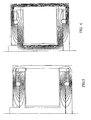
- the two permanent magnets 3a, 3b are working independent from each other and generates a static magnetic field which is illustrated in figure 2 . As shown in the figure the magnetic field is passing through only a part of the construction and the air gaps 6a, 6b, but not through the core 2a of the coil.
- a dynamic magnetic field is generated as illustrated in figure 3 .
- a substantial part of the vibrator is passed through only by the dynamic magnetic field, except from the permanent magnets, and as the dynamic magnetic field is small compared to the static field these parts of the vibrator can be made with smaller dimensions (thinner) as the required material thickness is proportional to the strength of the magnetic field. Furthermore these parts can be made of a material which is more suitable for alternating fields. Consequently a substantial part of the vibrator volume can be used for the power generating coil.
- the power is generated in the air gaps 6a, 6b between the bobbin and the casing when a current is passing through the coil.
- the air gaps have the same size; no static force is acting and the inner spring mechanism does not need to be pre-loaded.
- the coil 1 the bobbin 2 and the annular magnets 3a, 3b, i e the entire coil and magnet assembly, is moved relative to the casing so that an axial force is obtained as indicated by the arrow 7 in figure 1 .
- the inner spring mechanism 5a, 5b is chosen in such a way that a satisfacory resonant frequency is obtained from an audiological and effectiveness point of view.
- the dynamic and static magnetic fields are substantially separated from each other. However, they are coinciding in that part of the vibrator device where it is desirable for the power generation that the fields are coinciding, i e in the air gaps 6a, 6b.
- FIG 4 another example of a vibrator design is illustrated in which the annular permanent magnets 3a, 3b and the coil 1 instead are attached to the casing 4.
- the vibrator force is obtained through the bobbin 2 which is allowed to project out from the casing.
- the two annular permanent magnets 3a, 3b are working independent from each other and are generating a static magnetic field according to figure 5 .
- a dynamic field is generated as illustrated in figure 6 .
- the static and the dynamic magnetic fields are substantially separated from each other, but the fields are coinciding in that part of the vibrator where it is desired with such coinciding fields, i e in the air gaps.
- a third vibrator device which also comprises two permanent magnets like the first examples.
- annular permanent magnets illustrated in the two first embodiments in this case the axially magnetized permanent magnets 3a, 3b are located centrally. They are each arranged in its own centrally located recess in the outer side of the bobbin wall, adjacent to core 2a of the coil and they are disc-shaped (puck-shaped).
- the static and dynamic magnetic fields generated by this third embodiment are illustrated in figures 8 and 9 . Again, it should be clear that the magnetic fields are substantially separated, but they coincide where this is best needed, i. e. in the air gaps. Specifically, the static field only goes through a part of the construction and the dynamic field does not go through the permanent magnets.
- the permanent magnets are axially magnetized.
- FIG 10 there is an example where the permanent magnets 3a, 3b are radially magnetized.
- the magnets are annular and arranged on the end surfaces 8a, 8b of the side walls of the bobbin. Even in this case the static and dynamic fields are separated, as illustrated in figures 11 and 12 . Specifically, the static field does not in any case go through the core 2a of the coil.
- the casing 4 protects the entire construction.
- the vibrator is specifically intended to be used in connection with a bone conduction hearing aid device.
- the casing 4 of the vibrator is resting directly against the skull of the patient.
- bone conduction hearing aid coupling means are arranged on the casing for connection to an implant, for instance a titanium screw, a so-called fixture, anchored in the skull bone.
- an implanted bone conductor the vibrator is used with or without coupling means depending on the implant method.
Landscapes
- Physics & Mathematics (AREA)
- Engineering & Computer Science (AREA)
- Acoustics & Sound (AREA)
- Signal Processing (AREA)
- Health & Medical Sciences (AREA)
- General Health & Medical Sciences (AREA)
- Otolaryngology (AREA)
- Neurosurgery (AREA)
- Electromagnetism (AREA)
- Apparatuses For Generation Of Mechanical Vibrations (AREA)
- Electrostatic, Electromagnetic, Magneto- Strictive, And Variable-Resistance Transducers (AREA)
- Investigating Or Analyzing Materials By The Use Of Ultrasonic Waves (AREA)
Claims (18)
- Vibrator für Hörhilfen der Knochenleitungsbauart, das heißt Hörhilfevorrichtungen, durch welche die Toninformation mechanisch über den Schädelknochen direkt auf das Innenohr einer Person mit Schwerhörigkeit übertragen wird, wobei der Vibrator eine Spule (1) zum Erzeugen eines dynamischen Magnetfeldes und Permanentmagnetmittel (3a, 3b) zum Erzeugen eines statischen Magnetfeldes in einer Magnetschaltung aufweist, dadurch gekennzeichnet, dass die Permanentmagnetmittel zwei Permanentmagnete (3a, 3b) aufweisen, die unabhängig voneinander in der Magnetschaltung arbeiten und so angeordnet sind, dass das statische und das dynamische Magnetfeld im Wesentlichen voneinander getrennten sind, wodurch das statische Feld nur durch einen Teil der Magnetschaltung hindurchgeht und wodurch der Vibrator eine Axialkraft (7) bereitstellt.
- Vibrator nach Anspruch 1, dadurch gekennzeichnet, dass die gesamte Spulen- und Magnetanordnung in einem Gehäuse (4) eingeschlossen ist, das einen Teil der Magnetschaltung bildet und den Vibrator schützt und magnetische Streuung verringert.
- Vibrator nach Anspruch 2, dadurch gekennzeichnet, dass das statische und das dynamische Magnetfeld in den Luftspalten (6a, 6b), welche zwischen der Spulen- und Magnetanordnung und dem Gehäuse (4) ausgebildet sind, zusammentreffen.
- Vibrator nach Anspruch 3, dadurch gekennzeichnet, dass zwischen der Spulen- und Magnetanordnung und dem Gehäuse (4) innere Federmittel (5a, 5b) so angeordnet sind, dass die Spulen- und Magnetanordnung in ihrer Ruheposition in dem Gehäuse (4) zwischen zwei Luftspalten (6a, 6b) gleicher Größe zentriert ist.
- Vibrator nach Anspruch 3, dadurch gekennzeichnet, dass in der Spulen- und Magnetanordnung und in den gegenüberliegenden Teilen des Gehäuses (4) einander abstoßende Magnete angeordnet sind, so dass die Spulen- und Magnetanordnung in ihrer Ruheposition in dem Gehäuse (4) zwischen zwei Luftspalten (6a, 6b) gleicher Größe zentriert ist.
- Vibrator nach Anspruch 3, dadurch gekennzeichnet, dass der Vibrator mit einer Flüssigkeit gefüllt ist, um die Vibrationsbewegungen der Spulen- und Magnetanordnungen zu dämpfen.
- Vibrator nach Anspruch 1, dadurch gekennzeichnet, dass die Spule (1), um eine Spulenbasis (2) mit einem Kern (2a) und zwei Seitenwänden (2c, 2d) mit zwei äußeren Aussparungen, in welchen die zwei Permanentmagnete (3a, 3b) befestigt sind, gewickelt ist.
- Vibrator nach Anspruch 7, dadurch gekennzeichnet, dass die Permanentmagnete (3a, 3b) axial magnetisiert sind.
- Vibrator nach Anspruch 7, dadurch gekennzeichnet, dass die zwei Aussparungen für die Befestigung von zwei ringförmigen Permanentmagneten (3a, 3b) ringförmig sind und peripher angeordnet sind.
- Vibrator nach Anspruch 7, dadurch gekennzeichnet, dass die zwei Aussparungen für die Befestigung von zwei scheibenförmigen Permanentmagneten (3a, 3b) zentral gelegen sind.
- Vibrator nach Anspruch 1, dadurch gekennzeichnet, dass die Spule (1) und die Permanentmagnete (3a, 3b) an dem Gehäuse (4) befestigt sind, in welchem Fall die Axialkraft (7) vom Vibrator durch den Spulenkörper (2) erzielt wird, der an dem Gehäuse (4) vorsteht.
- Vibrator nach Anspruch 1, dadurch gekennzeichnet, dass die Spule (1) um eine Spulenbasis (2) mit einem Kern (2a) und zwei Seitenwänden (2c, 2d) gewickelt ist, in welchem Fall die zwei Permanentmagnete (3a, 3b) an den Endflächen (8a, 8b) der Seitenwände angeordnet sind.
- Vibrator nach Anspruch 12, dadurch gekennzeichnet, dass die Permanentmagnete (3a, 3b) ringförmig sind und radialmagnetisiert sind.
- Vibrator nach Anspruch 1, dadurch gekennzeichnet, dass die Magnetschaltung so angeordnet ist, dass das statische Magnetfeld nicht durch den Kern (2a) der Spule hindurch geht und dass das dynamische Magnetfeld nicht durch die Permanentmagnete (3a, 3b) hindurch geht.
- Vibrator nach Anspruch 1, dadurch gekennzeichnet, dass der Vibrator in einer Knochenleitungshörhilfevorrichtung von der Bauart enthalten ist, die einen externen Teil mit einem Mikrophon und einer elektronischen Schaltung und einen internen, implantierbaren Teil aufweist, der subkutan auf dem Schädelknochen zu Verankern ist, und in welchem Fall der Vibrator in dem implantierbaren Teil angeordnet ist.
- Vibrator nach Anspruch 15, dadurch gekennzeichnet, dass die erforderliche Energie für den Vibrator mittels Induktion bereitgestellt wird.
- Vibrator nach Anspruch 15, dadurch gekennzeichnet, dass die erforderliche Energie für den Vibrator mittels einer wiederaufladbaren Batterie bereitgestellt wird, die in dem implantierbaren Teil des Vibrators angeordnet ist.
- Vibrator nach Anspruch 15, dadurch gekennzeichnet, dass der Vibrator direkt mit einem in den Knochen integrierten Teil des implantierbaren Teils verbunden ist.
Applications Claiming Priority (3)
| Application Number | Priority Date | Filing Date | Title |
|---|---|---|---|
| SE0002073 | 2000-06-02 | ||
| SE0002073A SE514929C2 (sv) | 2000-06-02 | 2000-06-02 | Vibrator för benförankrade samt benledningshörapparater |
| PCT/SE2001/001227 WO2001093633A1 (en) | 2000-06-02 | 2001-05-31 | Vibrator for boneconducted hearing aids |
Publications (2)
| Publication Number | Publication Date |
|---|---|
| EP1305979A1 EP1305979A1 (de) | 2003-05-02 |
| EP1305979B1 true EP1305979B1 (de) | 2009-01-14 |
Family
ID=20279950
Family Applications (1)
| Application Number | Title | Priority Date | Filing Date |
|---|---|---|---|
| EP01937100A Expired - Lifetime EP1305979B1 (de) | 2000-06-02 | 2001-05-31 | Vibrator für knochenleitungs-hörhilfen |
Country Status (8)
| Country | Link |
|---|---|
| US (1) | US7319771B2 (de) |
| EP (1) | EP1305979B1 (de) |
| AT (1) | ATE421229T1 (de) |
| AU (1) | AU2001262865A1 (de) |
| DE (1) | DE60137429D1 (de) |
| DK (1) | DK1305979T3 (de) |
| SE (1) | SE514929C2 (de) |
| WO (1) | WO2001093633A1 (de) |
Cited By (1)
| Publication number | Priority date | Publication date | Assignee | Title |
|---|---|---|---|---|
| CN113691914A (zh) * | 2017-12-22 | 2021-11-23 | 谷歌有限责任公司 | 二维分布式模式致动器 |
Families Citing this family (27)
| Publication number | Priority date | Publication date | Assignee | Title |
|---|---|---|---|---|
| SE516270C2 (sv) * | 2000-03-09 | 2001-12-10 | Osseofon Ab | Elektromagnetisk vibrator |
| US7471801B2 (en) | 2002-05-10 | 2008-12-30 | Osseofon Ab | Device for the generation of or monitoring of vibrations |
| SE522164C2 (sv) * | 2002-05-10 | 2004-01-20 | Osseofon Ab | Anordning vid elektromagnetisk vibrator |
| SE525631C2 (sv) * | 2003-09-19 | 2005-03-22 | P & B Res Ab | Metod och anordning för att dämpa resonansfrekvens |
| US7376237B2 (en) * | 2004-09-02 | 2008-05-20 | Oticon A/S | Vibrator for bone-conduction hearing |
| SE528279C2 (sv) | 2005-02-21 | 2006-10-10 | Entific Medical Systems Ab | Vibrator för benledande hörapparat |
| US8246532B2 (en) | 2006-02-14 | 2012-08-21 | Vibrant Med-El Hearing Technology Gmbh | Bone conductive devices for improving hearing |
| SE0600843L (sv) | 2006-04-12 | 2007-10-13 | Osseofon Ab | Metod vid tillverkning av balanserad vibrator |
| SE531053C2 (sv) | 2007-05-24 | 2008-12-02 | Cochlear Ltd | Vibrator |
| US20100329485A1 (en) * | 2008-03-17 | 2010-12-30 | Temco Japan Co., Ltd. | Bone conduction speaker and hearing device using the same |
| US20090248085A1 (en) | 2008-03-31 | 2009-10-01 | Cochlear Limited | Tissue injection fixation system for a prosthetic device |
| US8144909B2 (en) | 2008-08-12 | 2012-03-27 | Cochlear Limited | Customization of bone conduction hearing devices |
| DE102009014770A1 (de) | 2009-03-25 | 2010-09-30 | Cochlear Ltd., Lane Cove | Schwingungserzeuger |
| USRE48797E1 (en) | 2009-03-25 | 2021-10-26 | Cochlear Limited | Bone conduction device having a multilayer piezoelectric element |
| DE102009014774A1 (de) | 2009-03-25 | 2010-09-30 | Cochlear Ltd., Lane Cove | Hörhilfevorrichtung |
| SE1000876A1 (sv) * | 2010-08-28 | 2011-12-27 | Osseofon Ab | Miniatyriserad variabel reluktansvibrator |
| US8565461B2 (en) | 2011-03-16 | 2013-10-22 | Cochlear Limited | Bone conduction device including a balanced electromagnetic actuator having radial and axial air gaps |
| US9479879B2 (en) | 2011-03-23 | 2016-10-25 | Cochlear Limited | Fitting of hearing devices |
| US9107013B2 (en) | 2011-04-01 | 2015-08-11 | Cochlear Limited | Hearing prosthesis with a piezoelectric actuator |
| JP5591314B2 (ja) * | 2012-12-18 | 2014-09-17 | 京セラ株式会社 | 骨伝導振動素子を具えた電子機器 |
| US9432782B2 (en) * | 2013-03-14 | 2016-08-30 | Cochlear Limited | Electromagnetic transducer with air gap substitute |
| US9716953B2 (en) | 2013-03-15 | 2017-07-25 | Cochlear Limited | Electromagnetic transducer with specific internal geometry |
| AT516871B1 (de) * | 2015-03-05 | 2018-03-15 | Bhm Tech Produktionsgesellschaft M B H | Elektromagnetischer Signalwandler für einen Knochenleitungshörer |
| US11778385B2 (en) | 2017-06-23 | 2023-10-03 | Cochlear Limited | Electromagnetic transducer with non-axial air gap |
| US11035830B2 (en) | 2017-06-23 | 2021-06-15 | Cochlear Limited | Electromagnetic transducer with dual flux |
| WO2020129021A1 (en) * | 2018-12-21 | 2020-06-25 | Cochlear Limited | Advanced bone conduction implant |
| EP3780654B1 (de) * | 2019-08-15 | 2025-05-14 | Oticon Medical A/S | Transkutanes, im knochen verankertes hörgerät mit reduzierter dicke |
Family Cites Families (23)
| Publication number | Priority date | Publication date | Assignee | Title |
|---|---|---|---|---|
| US905781A (en) | 1908-01-29 | 1908-12-01 | William Witt | Telephone-receiver. |
| US2500541A (en) * | 1945-07-18 | 1950-03-14 | Emil H Greibach | Inertia-type electromechanical sound transducing device |
| SE431705B (sv) | 1981-12-01 | 1984-02-20 | Bo Hakansson | Koppling, foretredesvis avsedd for mekanisk overforing av ljudinformation till skallbenet pa en horselskadad person |
| SE447947B (sv) | 1985-05-10 | 1986-12-22 | Bo Hakansson | Anordning vid en horapparat |
| SE447948B (sv) | 1985-05-15 | 1986-12-22 | Bo Hakansson | Anordning vid for en vibrator till en horapparat eller annan for ljudstimulering av ben anordnad vibrationsalstrare avsedd fjeder |
| US4606329A (en) * | 1985-05-22 | 1986-08-19 | Xomed, Inc. | Implantable electromagnetic middle-ear bone-conduction hearing aid device |
| US4988333A (en) | 1988-09-09 | 1991-01-29 | Storz Instrument Company | Implantable middle ear hearing aid system and acoustic coupler therefor |
| DE3940632C1 (en) | 1989-06-02 | 1990-12-06 | Hortmann Gmbh, 7449 Neckartenzlingen, De | Hearing aid directly exciting inner ear - has microphone encapsulated for implantation in tympanic cavity or mastoid region |
| US5176620A (en) | 1990-10-17 | 1993-01-05 | Samuel Gilman | Hearing aid having a liquid transmission means communicative with the cochlea and method of use thereof |
| US5282858A (en) | 1991-06-17 | 1994-02-01 | American Cyanamid Company | Hermetically sealed implantable transducer |
| SE9301406D0 (sv) * | 1993-04-27 | 1993-04-27 | Medevelop Ab | Foee implantation i benvaevnad avsett haallarorgan foer kontrollerad upptagning och laegesfixering av foeretraedesvis foer elektrisk informationsoeverfoering anvaendbar utrustning samt saett foer dess applicering i benvaevnaden |
| US5913815A (en) * | 1993-07-01 | 1999-06-22 | Symphonix Devices, Inc. | Bone conducting floating mass transducers |
| US5897486A (en) | 1993-07-01 | 1999-04-27 | Symphonix Devices, Inc. | Dual coil floating mass transducers |
| US5800336A (en) * | 1993-07-01 | 1998-09-01 | Symphonix Devices, Inc. | Advanced designs of floating mass transducers |
| US5615229A (en) * | 1993-07-02 | 1997-03-25 | Phonic Ear, Incorporated | Short range inductively coupled communication system employing time variant modulation |
| AU703061B2 (en) | 1995-09-02 | 1999-03-11 | New Transducers Limited | Vibration transducers |
| SE507336C2 (sv) | 1995-10-12 | 1998-05-18 | Nobel Biocare Ab | Hållarorgan för implantation i benvävnad |
| JP2000508844A (ja) * | 1996-03-25 | 2000-07-11 | エス ジョージ レジンスキー | 埋め込み可能な補聴器マイクロアクチュエータの取付け装置 |
| JPH1157066A (ja) * | 1997-08-19 | 1999-03-02 | Bridgestone Sports Co Ltd | ゴルフボール |
| KR19980063410A (ko) | 1997-08-19 | 1998-10-07 | 양승택 | 골도 및 기도 청각 겸용의 수화갑이 구비된 전화기 |
| US6217508B1 (en) | 1998-08-14 | 2001-04-17 | Symphonix Devices, Inc. | Ultrasonic hearing system |
| SE516270C2 (sv) | 2000-03-09 | 2001-12-10 | Osseofon Ab | Elektromagnetisk vibrator |
| SE523123C2 (sv) | 2000-06-02 | 2004-03-30 | P & B Res Ab | Hörapparat som arbetar med principen benledning |
-
2000
- 2000-06-02 SE SE0002073A patent/SE514929C2/sv not_active IP Right Cessation
-
2001
- 2001-05-31 US US10/296,977 patent/US7319771B2/en not_active Expired - Fee Related
- 2001-05-31 DE DE60137429T patent/DE60137429D1/de not_active Expired - Lifetime
- 2001-05-31 WO PCT/SE2001/001227 patent/WO2001093633A1/en not_active Ceased
- 2001-05-31 AT AT01937100T patent/ATE421229T1/de active
- 2001-05-31 DK DK01937100T patent/DK1305979T3/da active
- 2001-05-31 AU AU2001262865A patent/AU2001262865A1/en not_active Abandoned
- 2001-05-31 EP EP01937100A patent/EP1305979B1/de not_active Expired - Lifetime
Cited By (1)
| Publication number | Priority date | Publication date | Assignee | Title |
|---|---|---|---|---|
| CN113691914A (zh) * | 2017-12-22 | 2021-11-23 | 谷歌有限责任公司 | 二维分布式模式致动器 |
Also Published As
| Publication number | Publication date |
|---|---|
| SE0002073L (sv) | 2001-05-21 |
| EP1305979A1 (de) | 2003-05-02 |
| US7319771B2 (en) | 2008-01-15 |
| WO2001093633A1 (en) | 2001-12-06 |
| DK1305979T3 (da) | 2009-03-23 |
| SE514929C2 (sv) | 2001-05-21 |
| DE60137429D1 (de) | 2009-03-05 |
| AU2001262865A1 (en) | 2001-12-11 |
| SE0002073D0 (sv) | 2000-06-02 |
| US20040028249A1 (en) | 2004-02-12 |
| ATE421229T1 (de) | 2009-01-15 |
Similar Documents
| Publication | Publication Date | Title |
|---|---|---|
| EP1305978B1 (de) | Vibrator für knochenleitungs-hörhilfen | |
| EP1305979B1 (de) | Vibrator für knochenleitungs-hörhilfen | |
| EP1882386B1 (de) | Vibrator | |
| US20040032962A1 (en) | Bone conducting hearing aid | |
| US6735318B2 (en) | Middle ear hearing aid transducer | |
| EP2538700B1 (de) | Schwingungseinheit für Schädelknochen | |
| US6084975A (en) | Promontory transmitting coil and tympanic membrane magnet for hearing devices | |
| US7442164B2 (en) | Totally implantable hearing prosthesis | |
| EP1457090B1 (de) | Vibratordämpfung | |
| EP1483937A1 (de) | Hörgerätevorrichtung | |
| US8620015B2 (en) | Vibrator for bone conducting hearing devices | |
| EP1671514B1 (de) | Verfahren und anordnung zum dämpfen einer resonanzfrequenz | |
| CN121751066A (zh) | 一种可植入助听器系统 |
Legal Events
| Date | Code | Title | Description |
|---|---|---|---|
| PUAI | Public reference made under article 153(3) epc to a published international application that has entered the european phase |
Free format text: ORIGINAL CODE: 0009012 |
|
| 17P | Request for examination filed |
Effective date: 20021219 |
|
| AK | Designated contracting states |
Designated state(s): AT BE CH CY DE DK ES FI FR GB GR IE IT LI LU MC NL PT SE TR |
|
| AX | Request for extension of the european patent |
Extension state: AL LT LV MK RO SI |
|
| GRAP | Despatch of communication of intention to grant a patent |
Free format text: ORIGINAL CODE: EPIDOSNIGR1 |
|
| RIC1 | Information provided on ipc code assigned before grant |
Ipc: H04R 9/02 20060101ALN20080716BHEP Ipc: H04R 9/00 20060101ALN20080716BHEP Ipc: H04R 25/00 20060101AFI20080716BHEP Ipc: H04R 25/02 20060101ALN20080716BHEP |
|
| GRAS | Grant fee paid |
Free format text: ORIGINAL CODE: EPIDOSNIGR3 |
|
| GRAS | Grant fee paid |
Free format text: ORIGINAL CODE: EPIDOSNIGR3 |
|
| GRAA | (expected) grant |
Free format text: ORIGINAL CODE: 0009210 |
|
| AK | Designated contracting states |
Kind code of ref document: B1 Designated state(s): AT BE CH CY DE DK ES FI FR GB GR IE IT LI LU MC NL PT SE TR |
|
| REG | Reference to a national code |
Ref country code: GB Ref legal event code: FG4D |
|
| REG | Reference to a national code |
Ref country code: CH Ref legal event code: EP |
|
| REG | Reference to a national code |
Ref country code: IE Ref legal event code: FG4D |
|
| REF | Corresponds to: |
Ref document number: 60137429 Country of ref document: DE Date of ref document: 20090305 Kind code of ref document: P |
|
| REG | Reference to a national code |
Ref country code: CH Ref legal event code: NV Representative=s name: E. BLUM & CO. AG PATENT- UND MARKENANWAELTE VSP |
|
| REG | Reference to a national code |
Ref country code: DK Ref legal event code: T3 |
|
| PG25 | Lapsed in a contracting state [announced via postgrant information from national office to epo] |
Ref country code: NL Free format text: LAPSE BECAUSE OF FAILURE TO SUBMIT A TRANSLATION OF THE DESCRIPTION OR TO PAY THE FEE WITHIN THE PRESCRIBED TIME-LIMIT Effective date: 20090114 |
|
| REG | Reference to a national code |
Ref country code: CH Ref legal event code: PUE Owner name: OSSEOFON AB Free format text: P & B RESEARCH AB#SPLINTVEDSGATAN 7#416 80 GOETEBORG (SE) -TRANSFER TO- OSSEOFON AB#SPLINTVEDSGATAN 7#41680 GOETEBORG (SE) |
|
| NLV1 | Nl: lapsed or annulled due to failure to fulfill the requirements of art. 29p and 29m of the patents act | ||
| REG | Reference to a national code |
Ref country code: FR Ref legal event code: TP |
|
| REG | Reference to a national code |
Ref country code: GB Ref legal event code: 732E Free format text: REGISTERED BETWEEN 20090702 AND 20090708 |
|
| PG25 | Lapsed in a contracting state [announced via postgrant information from national office to epo] |
Ref country code: ES Free format text: LAPSE BECAUSE OF FAILURE TO SUBMIT A TRANSLATION OF THE DESCRIPTION OR TO PAY THE FEE WITHIN THE PRESCRIBED TIME-LIMIT Effective date: 20090425 Ref country code: FI Free format text: LAPSE BECAUSE OF FAILURE TO SUBMIT A TRANSLATION OF THE DESCRIPTION OR TO PAY THE FEE WITHIN THE PRESCRIBED TIME-LIMIT Effective date: 20090114 |
|
| PG25 | Lapsed in a contracting state [announced via postgrant information from national office to epo] |
Ref country code: PT Free format text: LAPSE BECAUSE OF FAILURE TO SUBMIT A TRANSLATION OF THE DESCRIPTION OR TO PAY THE FEE WITHIN THE PRESCRIBED TIME-LIMIT Effective date: 20090615 Ref country code: SE Free format text: LAPSE BECAUSE OF FAILURE TO SUBMIT A TRANSLATION OF THE DESCRIPTION OR TO PAY THE FEE WITHIN THE PRESCRIBED TIME-LIMIT Effective date: 20090414 |
|
| PG25 | Lapsed in a contracting state [announced via postgrant information from national office to epo] |
Ref country code: BE Free format text: LAPSE BECAUSE OF FAILURE TO SUBMIT A TRANSLATION OF THE DESCRIPTION OR TO PAY THE FEE WITHIN THE PRESCRIBED TIME-LIMIT Effective date: 20090114 |
|
| PLBE | No opposition filed within time limit |
Free format text: ORIGINAL CODE: 0009261 |
|
| STAA | Information on the status of an ep patent application or granted ep patent |
Free format text: STATUS: NO OPPOSITION FILED WITHIN TIME LIMIT |
|
| 26N | No opposition filed |
Effective date: 20091015 |
|
| PG25 | Lapsed in a contracting state [announced via postgrant information from national office to epo] |
Ref country code: MC Free format text: LAPSE BECAUSE OF NON-PAYMENT OF DUE FEES Effective date: 20090531 |
|
| REG | Reference to a national code |
Ref country code: CH Ref legal event code: PL |
|
| PG25 | Lapsed in a contracting state [announced via postgrant information from national office to epo] |
Ref country code: LI Free format text: LAPSE BECAUSE OF NON-PAYMENT OF DUE FEES Effective date: 20090531 Ref country code: CH Free format text: LAPSE BECAUSE OF NON-PAYMENT OF DUE FEES Effective date: 20090531 |
|
| PGFP | Annual fee paid to national office [announced via postgrant information from national office to epo] |
Ref country code: DK Payment date: 20091110 Year of fee payment: 9 |
|
| REG | Reference to a national code |
Ref country code: IE Ref legal event code: MM4A |
|
| PG25 | Lapsed in a contracting state [announced via postgrant information from national office to epo] |
Ref country code: IE Free format text: LAPSE BECAUSE OF NON-PAYMENT OF DUE FEES Effective date: 20090531 |
|
| PGFP | Annual fee paid to national office [announced via postgrant information from national office to epo] |
Ref country code: GB Payment date: 20091111 Year of fee payment: 9 |
|
| PG25 | Lapsed in a contracting state [announced via postgrant information from national office to epo] |
Ref country code: GR Free format text: LAPSE BECAUSE OF FAILURE TO SUBMIT A TRANSLATION OF THE DESCRIPTION OR TO PAY THE FEE WITHIN THE PRESCRIBED TIME-LIMIT Effective date: 20090415 |
|
| REG | Reference to a national code |
Ref country code: DK Ref legal event code: EBP |
|
| GBPC | Gb: european patent ceased through non-payment of renewal fee |
Effective date: 20100531 |
|
| PG25 | Lapsed in a contracting state [announced via postgrant information from national office to epo] |
Ref country code: IT Free format text: LAPSE BECAUSE OF FAILURE TO SUBMIT A TRANSLATION OF THE DESCRIPTION OR TO PAY THE FEE WITHIN THE PRESCRIBED TIME-LIMIT Effective date: 20090114 |
|
| PG25 | Lapsed in a contracting state [announced via postgrant information from national office to epo] |
Ref country code: LU Free format text: LAPSE BECAUSE OF NON-PAYMENT OF DUE FEES Effective date: 20090531 Ref country code: DK Free format text: LAPSE BECAUSE OF NON-PAYMENT OF DUE FEES Effective date: 20100531 |
|
| PG25 | Lapsed in a contracting state [announced via postgrant information from national office to epo] |
Ref country code: GB Free format text: LAPSE BECAUSE OF NON-PAYMENT OF DUE FEES Effective date: 20100531 |
|
| PG25 | Lapsed in a contracting state [announced via postgrant information from national office to epo] |
Ref country code: TR Free format text: LAPSE BECAUSE OF FAILURE TO SUBMIT A TRANSLATION OF THE DESCRIPTION OR TO PAY THE FEE WITHIN THE PRESCRIBED TIME-LIMIT Effective date: 20090114 |
|
| PG25 | Lapsed in a contracting state [announced via postgrant information from national office to epo] |
Ref country code: CY Free format text: LAPSE BECAUSE OF FAILURE TO SUBMIT A TRANSLATION OF THE DESCRIPTION OR TO PAY THE FEE WITHIN THE PRESCRIBED TIME-LIMIT Effective date: 20090114 |
|
| REG | Reference to a national code |
Ref country code: FR Ref legal event code: PLFP Year of fee payment: 16 |
|
| REG | Reference to a national code |
Ref country code: FR Ref legal event code: PLFP Year of fee payment: 17 |
|
| REG | Reference to a national code |
Ref country code: FR Ref legal event code: PLFP Year of fee payment: 18 |
|
| PGFP | Annual fee paid to national office [announced via postgrant information from national office to epo] |
Ref country code: DE Payment date: 20200507 Year of fee payment: 20 Ref country code: FR Payment date: 20200512 Year of fee payment: 20 |
|
| PGFP | Annual fee paid to national office [announced via postgrant information from national office to epo] |
Ref country code: AT Payment date: 20200507 Year of fee payment: 20 |
|
| REG | Reference to a national code |
Ref country code: DE Ref legal event code: R071 Ref document number: 60137429 Country of ref document: DE |
|
| REG | Reference to a national code |
Ref country code: AT Ref legal event code: MK07 Ref document number: 421229 Country of ref document: AT Kind code of ref document: T Effective date: 20210531 |