EP1306177A2 - Dispositif de pressage, en particulier pour le pressage de pièces moulées en matière céramique - Google Patents
Dispositif de pressage, en particulier pour le pressage de pièces moulées en matière céramique Download PDFInfo
- Publication number
- EP1306177A2 EP1306177A2 EP02023684A EP02023684A EP1306177A2 EP 1306177 A2 EP1306177 A2 EP 1306177A2 EP 02023684 A EP02023684 A EP 02023684A EP 02023684 A EP02023684 A EP 02023684A EP 1306177 A2 EP1306177 A2 EP 1306177A2
- Authority
- EP
- European Patent Office
- Prior art keywords
- press
- tool
- filling
- molded part
- pressing
- Prior art date
- Legal status (The legal status is an assumption and is not a legal conclusion. Google has not performed a legal analysis and makes no representation as to the accuracy of the status listed.)
- Granted
Links
Images



Classifications
-
- B—PERFORMING OPERATIONS; TRANSPORTING
- B30—PRESSES
- B30B—PRESSES IN GENERAL
- B30B15/00—Details of, or accessories for, presses; Auxiliary measures in connection with pressing
- B30B15/30—Feeding material to presses
- B30B15/302—Feeding material in particulate or plastic state to moulding presses
-
- B—PERFORMING OPERATIONS; TRANSPORTING
- B28—WORKING CEMENT, CLAY, OR STONE
- B28B—SHAPING CLAY OR OTHER CERAMIC COMPOSITIONS; SHAPING SLAG; SHAPING MIXTURES CONTAINING CEMENTITIOUS MATERIAL, e.g. PLASTER
- B28B5/00—Producing shaped articles from the material in moulds or on moulding surfaces, carried or formed by, in or on conveyors irrespective of the manner of shaping
- B28B5/04—Producing shaped articles from the material in moulds or on moulding surfaces, carried or formed by, in or on conveyors irrespective of the manner of shaping in moulds moved in succession past one or more shaping stations
-
- B—PERFORMING OPERATIONS; TRANSPORTING
- B30—PRESSES
- B30B—PRESSES IN GENERAL
- B30B11/00—Presses specially adapted for forming shaped articles from material in particulate or plastic state, e.g. briquetting presses, tabletting presses
- B30B11/02—Presses specially adapted for forming shaped articles from material in particulate or plastic state, e.g. briquetting presses, tabletting presses using a ram exerting pressure on the material in a moulding space
- B30B11/14—Presses specially adapted for forming shaped articles from material in particulate or plastic state, e.g. briquetting presses, tabletting presses using a ram exerting pressure on the material in a moulding space co-operating with moulds on a movable carrier other than a turntable or a rotating drum
Definitions
- the invention relates to a press arrangement for Pressing in particular ceramic or metallurgical Compacts with the generic characteristics of Claim 1.
- Ceramic articles for example deep salad bowls
- a tool With vertical presses, a tool is between two vertically movable towards or away from each other Press stamps stretched.
- the tool has at least two Molded parts, between which a molded part space which consists of a ceramic one before pressing Powder or granulate is filled.
- the filling takes place either through at least one filling channel from the outside assembled molded parts or before putting on a upper molding to a lower molding by filling of the lower molding.
- After clamping and pressing the Molded parts in the press are the powder or granules into one compacted ceramic compact or ceramic article.
- the post-processing exists in particular from deburring, grinding and one Sponged before the pellet burned in an oven becomes.
- the molded parts can be in the simplest embodiment be attached directly to the press dies, but what disadvantageously long downtimes when replacing Has molded parts. Therefore, the molded parts in the Usually provided as part of a tool, so that parts of the assembly work outside of the actual Press can be made and only a limited number of tool parts with molded parts attached to them in the Press must be installed permanently.
- the long filling times are in Comparison to the filling times with a vertical filling of the molded part space in a horizontal press disadvantageous, so that compared to horizontal presses only a low output or a lower press cycle is achievable.
- In the case of compacts with a higher upward running edge there is also the problem that in a sufficient density of pressed material can be achieved in the lower area is, however, towards the upper edge just as with very large dimensioned compacts in their central area Filling defects can be expected from segregation, for example is. This leads to shadows and streaks and one correspondingly high committee.
- Die casting systems are also used to manufacture ceramic articles known in the casting process with porous plastic molds.
- Due to the porous plastic molds Liquid from the molded part space through the molded parts escape so that a solid body or pellet or Ceramic article remains. This is then after a removed from the molded part for a correspondingly long waiting time and postprocessed.
- Die casting systems have an im Compared to the presses described above clearly lower piece output per unit of time and also Article design restrictions. In particular the body thickness and the dimension of the articles can only be freely selected to a limited extent.
- the Die casting systems pose the risk of deformation during demolding of the ceramic article from the molded parts, because of this of a remaining liquid content compared to pressed ceramic articles only have a lower strength having.
- roller systems For the production of deep jugs or vases, for example conventional casting or roller systems are also known, which, however, also only has a low unit output enable and also cannot be fully automated.
- roller systems a ceramic raw mass is placed on one rotating disc applied and similar in basic principle the pottery with a potter's wheel to a ceramic article shaped.
- DE 198 55 753 A1 describes one method and one Device for the hydraulic forming of workpieces known.
- This document is the use of Spacer elements in the form of flat metal cuboids between a tool part and an inner wall of a Removable upper part of the press.
- An example for such presses can be found in EP 0 388 721 A2.
- This Press has a die with a stamp carrier to carry and moving stamps within the die. at fully or partially lowered stamp carrier is the resulting space with a powdered material to be pressed fillable to then press a compact.
- a filling shoe according to DE 198 51 527 A1 be used.
- Such presses often have interchangeable tool frame or molding on like this is known from, for example, DE 196 24 298 A1.
- JP 09038796 A is an exchange system for various such tools or molds are known, a variety of tools in an arrangement rotating about an axis compared to one located outside of this arrangement Press device is pivotable. With a hydraulic The pusher system can push one mold into the press or withdrawn from this. This enables one quick mold change for the production of different types Compacts. The filling takes place in all these arrangements the molds with a powder to be pressed in the press instead of. The mold is located during the Filling in the later pressing position, d. H. With their usually horizontal top edge in one plane perpendicular to the pressing direction.
- the object of the invention is a To provide press arrangement, the one hand a short Cycle time with free design options the compacts or ceramic articles.
- a press arrangement for Pressing ceramic compacts an actual press and one or more tool supply or Tool processing facility outside of the actual Press on.
- Using a tool transfer device the tool between these two basic positions and be moved here.
- To make handling as easy as possible enable is the actual tool with the molded parts designed as an adapter.
- a such press arrangement the filling of the tool or free space between the molded parts in the tool outside the actual press and also in one compared to the press position at the level of the press force pivoted position of the tool or the molded parts.
- the Position adjustment option by the Position adjustment device and on the other hand the filling outside the actual press by means of the tool filling device, each in accordance with the features of claims 7 or 8 independently inventive and are characterized by the ideal Combination of both options connected according to the invention.
- a variety of such tooling facilities and corresponding tool relocation devices outside the actual press and the use of an adapter with inserted top and Bottoming offers a wide variety Variations.
- Via appropriate manual Measures or automatically by means of a control device performed motion sequences can, for example different tools for completely different Pellet molds are used on a press. this will by arranging all molded parts within one Adapters allows.
- Advantageously can also on a tool supply device in the corresponding adapter complex compacts for the Prepared pressing process or after the pressing process from the Tool can be removed while using the other adapters on the other tool supply facilities simple ceramic articles with a short cycle time be prepared or removed. This allows a press ideally utilized, since the downtimes are minimized can be.
- an adapter with the one used Tool and molded parts is especially the Provision of a tool filling device possible in addition to a holding device for holding the adapter or Tool with assembled moldings and a usual Filling device for filling the molded part space with a press item also a position adjustment device having. It is by means of the position adjustment device possible, the adapter or the tool in preferably bring any layers, so that for example one Arrangement of the molded parts for a vertical pressing process a pivoting of the entire arrangement for filling in a 90 ° offset position is possible.
- the position adjustment device the preferably a pivoting mechanism for the adapter or the tool has the advantages of facing both horizontal and vertical presses the filling of the molded part space and with a view of the Removal of the compact. In particular, it is also possible an adjustment of the position in different spatial directions between the two layers described above enable.
- an adapter with inserted tools and used molded parts enables easy handling, a quick exchange and especially the connection of supply lines from the adapter or tool during the time in the press and in the area of assigned tool provision device not must be removed.
- FIG. 1 there is a press arrangement a variety of individual components. These are in particular a central press 2, three delivery devices 3 with transfer devices 4, the subsequently as tool relocation or Tool moving devices 4 are referred to, and the Adapters 5 with tools and molded parts used therein. Furthermore, at least one powder silo 6 for receiving powdery and / or granular pressed material and at least one press hydraulic 7 part of the Press arrangement 1.
- the press 2 consists essentially of known Press elements, in particular with a press base plate a hydraulic arrangement and a lower press ram 22 and an upper press assembly with an upper one Press plate 21 and one directly or indirectly on it arranged upper press ram 23.
- a short press stroke is preferably sufficient for the production of ceramic Household items, such as plates and bowls.
- the Press arrangement 1 also a control device C.
- the Control device C in addition to controlling the actual Pressing process to control the other components of the Press arrangement 1.
- a drive 34 Arrangement of the carriage 32 together with the patch Adapter 5 between the press position within the press 2 and the processing position in the processing or Provision device 3 move.
- you can however also any other robot-like adjustment and Movement mechanisms are used.
- Removal robot 8 can be according to a special Control specification after lifting off the upper molded part 52 access the compact 61 in the lower molding 54. This is particularly a targeted article removal the lower part of the tool, so that special and complex optical detection systems or Visualization systems for aligning the compact 61 do not have to be provided.
- the removal robot 8 can optionally remove the pressed compact 61 directly onto a Place belt 81 for removal or the removed compact 61 previously one or more individual stations Feed postprocessing station 82.
- FIG. 1 a lifting device 9 is shown in FIG. 1, which is explained in more detail below with reference to FIGS. 3 and 6.
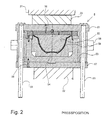
- FIGS. 2 and 3 there is an adapter 5 with a tool and molded parts from a variety of individual components.
- an adapter frame from an upper tool part 51 for fastening an upper one Molding 52, a lower tool part 53 for attaching one or more lower mold parts 54 and one Guide device or guide rods 55, the whole or partly by the upper tool part 51 and that Lower part of the tool are guided and a movement of this enable each other towards or away from each other.
- Attachment of the upper mold part or 52 on Tool upper part 51 serve fastening devices 56, in simplest embodiment simple screws from Tool upper part 51 are guided into the upper mold part 52.
- any other are common Fastening options can be used.
- this is actual tool lower part formed in several parts and consists, as shown, of the actual Lower tool part 53, which is essentially U-shaped Receiving housing designed for deep lower mold parts 54 and a tool base plate 57 on which the actual Lower tool part 53 is attached.
- the tool hangers 58 are in a particularly preferred embodiment as the side protruding bolts executed. This makes it possible to Holding and carrying devices 33 as U-shaped Arrange gripping devices upright on the carriage 32 and an adapter 5 simply from above with the Tool suspension bolt 58 in the U-shaped or fork-shaped Holding and carrying devices 33 to use. As shown, is the spatial suspension for stable suspension of the adapter 5 Location of the tool suspensions or bolts 58 from the Tool base plate 57 moved upwards educated.
- the holding and carrying device 33 consists in the illustrated embodiment in addition to the U- or fork-shaped Bearing 35 for the insertable bolt 58 Tool suspension from a piston rod 34, which Can raise or lower the pin bearing 35 up or down.
- a piston rod 34 which Can raise or lower the pin bearing 35 up or down.
- the lower end of the piston rod 34 is immersed in a cylinder-piston arrangement 36 a, which in turn on a guide 37 the corresponding guide rail 31 is seated.
- a such an arrangement enables the lifting or lowering of the entire adapter 5 used, so that the adapter 5 in inserted the press and there on the lower stamp 22 can be discontinued.
- the adapter via a rail system 31 in the Actual press 2 retract, and there the lower one Press stamp 22 so far before the actual pressing process lift that the tool base plate 57 on the bottom Press stamp 22 rests.
- the adapter 5 is removed from the Press 2 into the adapter 5 assigned Provisioning device 3 moved or brought. There then the upper tool part 51 with the upper mold part 52nd raised upwards so that the compact 61 by means of the Removal device 8 removed from the lower molded part 54 can be.
- Lifting devices are provided.
- A is shown Lifting device 9 with a lifting pin 91 or lifting gripper in a bore 92 in the outer circumference of the upper tool part 51 engages.
- a cylinder-piston arrangement 93 then the upper tool part 51 together with the upper mold part 52 in the predetermined by the guide device 55 Movement areas are raised.
- Guide device 55 for connecting or guiding the individual tool parts is provided for opening and closing Moving the upper tool part 51 in addition provide appropriate positioning mechanism.
- Lifting devices can be used, for example cylinder-piston arrangements or gear arrangements instead of one the guide rods 55 in the adapter frame of the adapter 5 are used. However, this then makes the connection of additional hydraulic lines to the adapter 5 required which is why the arrangement with an external lifting device 9 is particularly preferred.
- the adapter 5 or that Tool for removing the compact 61, but in particular for filling with a filling material in the intermediate space 59 can be brought into any position. It is shown next to the horizontal alignment of the molded parts 52, 54 and Molding space 59 in particular a vertical Arrangement, so that a filling of the molded part space 59 can be done from above. The filling takes place by means of a correspondingly attached to the adapter Filling hose that leads to a powder silo 6 or by means of a filling hose nozzle 62, which in the desired Filling position is briefly attached to the adapter, however, what appropriate robotic mechanisms required makes.
- a position adjustment device 64 in the area of the tool supply device 3 arranged. It is also possible to use a combined stroke and position adjustment device 9, 64.
- the illustrated embodiment takes one Gripping device 65 in the side of the adapter frame and here e.g. annular pin bearing 35 protruding Bolt 58.
- the gripping device 65 grips on the one hand in the bolt 58 such that the bolt rotates and thus a pivoting of the entire adapter frame is possible, and on the other hand is in with its other end a corresponding motorized drive.
- molded parts 52, 54 for manufacturing a deep bowl are shown as pellet 61 are 4 an upper molded part 52 and a lower molded part 54 ' shown being shaped for making a flat plate are.
- a spacer 66 is inserted between them.
- the lower molded part 54 ′ can be moved through the spacer 66 through with the lower tool part 53 or Tool base plate 57 are firmly connected. Is possible but e.g. also a direct connection of the lower molding 54 'with the protruding edge of the lower tool part 53, see above that the spacer 66 is loose between these two is used.
- Fig. 6 shows a lifting device 85, which in the arrangement Carriage 32 and the carrying and holding devices 33 is integrated.
- the led out of the side of the adapter Support pin 58 is complete in one of these encompassing support ring 35 '.
- the attachment of the Support ring 35 'on the slide is via guide linkage 86 formed such that a movement in the up and down direction is possible.
- One serves to lift the support ring 35 ' simple cylinder-piston arrangement 87.
Landscapes
- Engineering & Computer Science (AREA)
- Mechanical Engineering (AREA)
- Manufacturing & Machinery (AREA)
- Chemical & Material Sciences (AREA)
- Ceramic Engineering (AREA)
- Press-Shaping Or Shaping Using Conveyers (AREA)
Applications Claiming Priority (2)
| Application Number | Priority Date | Filing Date | Title |
|---|---|---|---|
| DE2001152114 DE10152114A1 (de) | 2001-10-23 | 2001-10-23 | Pressenanordnung, insbesondere zum Pressen von keramischen Presslingen |
| DE10152114 | 2001-10-23 |
Publications (3)
| Publication Number | Publication Date |
|---|---|
| EP1306177A2 true EP1306177A2 (fr) | 2003-05-02 |
| EP1306177A3 EP1306177A3 (fr) | 2005-04-13 |
| EP1306177B1 EP1306177B1 (fr) | 2008-03-26 |
Family
ID=7703318
Family Applications (1)
| Application Number | Title | Priority Date | Filing Date |
|---|---|---|---|
| EP20020023684 Expired - Lifetime EP1306177B1 (fr) | 2001-10-23 | 2002-10-22 | Dispositif de pressage, en particulier pour le pressage de pièces moulées en matière céramique |
Country Status (2)
| Country | Link |
|---|---|
| EP (1) | EP1306177B1 (fr) |
| DE (2) | DE10152114A1 (fr) |
Cited By (1)
| Publication number | Priority date | Publication date | Assignee | Title |
|---|---|---|---|---|
| EP4681898A1 (fr) * | 2024-07-18 | 2026-01-21 | SAMA Maschinenbau GmbH | Fabrication d'un composant céramique coulé sous pression |
Families Citing this family (2)
| Publication number | Priority date | Publication date | Assignee | Title |
|---|---|---|---|---|
| DE102005045244B3 (de) * | 2005-09-22 | 2007-01-04 | Sama Maschinenbau Gmbh | Vorrichtung zur Herstellung von unrunden Keramikgegenständen |
| DE102012016344B4 (de) * | 2012-08-20 | 2015-05-28 | Sama Maschinenbau Gmbh | Vorrichtung und Verfahren, insbesondere zum isostatischen Pressen oder zum Druckgießen |
Family Cites Families (7)
| Publication number | Priority date | Publication date | Assignee | Title |
|---|---|---|---|---|
| US1639081A (en) * | 1924-06-21 | 1927-08-16 | Jay Trading Corp De | Die-molding apparatus for making articles of plastic material |
| US2095299A (en) * | 1936-11-09 | 1937-10-12 | Lake Erie Engineering Corp | Molding press |
| DE3909757A1 (de) * | 1989-03-23 | 1990-09-27 | Dorst Masch & Anlagen | Presse mit einem in die presse einsetzbaren werkzeuggestell |
| DE19624298B4 (de) * | 1996-06-18 | 2008-04-17 | Laeis Gmbh | Verfahren zum Herstellen eines Formteils |
| DE19730980C1 (de) * | 1997-07-18 | 1998-10-01 | Reiner Welz | Vorrichtung und Verfahren zur Herstellung von Formlingen |
| DE19851527A1 (de) * | 1998-11-09 | 2000-05-11 | Dorst Masch & Anlagen | Füllvorrichtung für axiale Pulverpressen |
| DE19855753A1 (de) * | 1998-12-03 | 2000-06-08 | Kuka Werkzeugbau Schwarzenberg | Verfahren und Vorrichtung zum hydraulischen Umformen von Werkstücken |
-
2001
- 2001-10-23 DE DE2001152114 patent/DE10152114A1/de not_active Withdrawn
-
2002
- 2002-10-22 EP EP20020023684 patent/EP1306177B1/fr not_active Expired - Lifetime
- 2002-10-22 DE DE50211953T patent/DE50211953D1/de not_active Expired - Lifetime
Cited By (1)
| Publication number | Priority date | Publication date | Assignee | Title |
|---|---|---|---|---|
| EP4681898A1 (fr) * | 2024-07-18 | 2026-01-21 | SAMA Maschinenbau GmbH | Fabrication d'un composant céramique coulé sous pression |
Also Published As
| Publication number | Publication date |
|---|---|
| DE10152114A1 (de) | 2003-04-30 |
| EP1306177A3 (fr) | 2005-04-13 |
| EP1306177B1 (fr) | 2008-03-26 |
| DE50211953D1 (de) | 2008-05-08 |
Similar Documents
| Publication | Publication Date | Title |
|---|---|---|
| EP0387535B1 (fr) | Procédé et installation pour la fabrication de moules de fonderie | |
| EP0556363B1 (fr) | Presse verticale et son procede d'utilisation | |
| DE2930874A1 (de) | Formvorrichtung | |
| EP3167723A1 (fr) | Dispositif et procédé de manipulation de meules de fromage | |
| EP0416334B1 (fr) | Dispositif pour désempiler, remplir et empiler des conteneurs qui sont égaux entre eux | |
| DE3320234A1 (de) | Verfahren und vorrichtung zum trimmen von keramischer ware | |
| AT122171B (de) | Fördereinrichtung für Glasgefäße. | |
| EP1306177A2 (fr) | Dispositif de pressage, en particulier pour le pressage de pièces moulées en matière céramique | |
| DE1923236B2 (de) | Vorrichtung zum Herstellen eines Behälters aus thermoplastischem Kunststoff | |
| DE2144388C3 (de) | Preßformmaschine | |
| DE3736813A1 (de) | Fertigungsstrasse fuer scheibenbremsbelaege | |
| DE3337243A1 (de) | Einrichtung zur fertigung gepresster gegenstaende | |
| EP0327825B1 (fr) | Machine à mouler | |
| EP0662027A1 (fr) | Installation de moulage et procede de moulage sous pression de pieces ceramiques | |
| EP0960708B1 (fr) | Presse pour tuiles | |
| DE2822028A1 (de) | Anlage zum herstellen von giessformhaelften in formkasten | |
| DE4344636C1 (de) | Schwenkbalkenpresse zum Pressen keramischer Formteile | |
| DE2910267C3 (de) | Mündungswerkzeug für eine IS-Glasformmaschine | |
| DE939530C (de) | Glasformmaschine und Verfahren zum Formen nahtloser Glasgegenstaende | |
| DE1241047B (de) | Verfahren und Maschine zum Herstellen von Giessformen | |
| EP0690774B1 (fr) | Moule de compression isostatique pour la production d'articles en forme de pots a paroi abrupte a partir de granule ceramique | |
| DE1584330C3 (fr) | ||
| EP1074360B1 (fr) | Installation de coulage sous pression multiaxiale avec axe de pivotement | |
| DE3140500A1 (de) | "einrichtung zum herstellen von roemern aus stroh und verfahren zum betreiben dieser einrichtung" | |
| DE3214826A1 (de) | Vorrichtung an dachziegel-revolverpressen |
Legal Events
| Date | Code | Title | Description |
|---|---|---|---|
| PUAI | Public reference made under article 153(3) epc to a published international application that has entered the european phase |
Free format text: ORIGINAL CODE: 0009012 |
|
| AK | Designated contracting states |
Designated state(s): AT BE BG CH CY CZ DE DK EE ES FI FR GB GR IE IT LI LU MC NL PT SE SK TR |
|
| AX | Request for extension of the european patent |
Extension state: AL LT LV MK RO SI |
|
| RAP1 | Party data changed (applicant data changed or rights of an application transferred) |
Owner name: DORST TECHNOLOGIES GMBH & CO. KG |
|
| PUAL | Search report despatched |
Free format text: ORIGINAL CODE: 0009013 |
|
| AK | Designated contracting states |
Kind code of ref document: A3 Designated state(s): AT BE BG CH CY CZ DE DK EE ES FI FR GB GR IE IT LI LU MC NL PT SE SK TR |
|
| AX | Request for extension of the european patent |
Extension state: AL LT LV MK RO SI |
|
| 17P | Request for examination filed |
Effective date: 20051011 |
|
| AKX | Designation fees paid |
Designated state(s): CZ DE IT |
|
| RIC1 | Information provided on ipc code assigned before grant |
Ipc: B28B 17/00 20060101ALI20070302BHEP Ipc: B30B 11/14 20060101ALI20070302BHEP Ipc: B28B 5/04 20060101AFI20070302BHEP Ipc: B30B 15/30 20060101ALI20070302BHEP |
|
| GRAP | Despatch of communication of intention to grant a patent |
Free format text: ORIGINAL CODE: EPIDOSNIGR1 |
|
| GRAS | Grant fee paid |
Free format text: ORIGINAL CODE: EPIDOSNIGR3 |
|
| GRAA | (expected) grant |
Free format text: ORIGINAL CODE: 0009210 |
|
| AK | Designated contracting states |
Kind code of ref document: B1 Designated state(s): CZ DE IT |
|
| REF | Corresponds to: |
Ref document number: 50211953 Country of ref document: DE Date of ref document: 20080508 Kind code of ref document: P |
|
| PLBE | No opposition filed within time limit |
Free format text: ORIGINAL CODE: 0009261 |
|
| STAA | Information on the status of an ep patent application or granted ep patent |
Free format text: STATUS: NO OPPOSITION FILED WITHIN TIME LIMIT |
|
| 26N | No opposition filed |
Effective date: 20081230 |
|
| REG | Reference to a national code |
Ref country code: DE Ref legal event code: R082 Ref document number: 50211953 Country of ref document: DE Representative=s name: THIELE, THOMAS, DIPL.-GEOPHYS. DR.RER.NAT., DE Ref country code: DE Ref legal event code: R082 Ref document number: 50211953 Country of ref document: DE Representative=s name: MEISSNER BOLTE PATENTANWAELTE RECHTSANWAELTE P, DE |
|
| REG | Reference to a national code |
Ref country code: DE Ref legal event code: R082 Ref document number: 50211953 Country of ref document: DE Representative=s name: MEISSNER BOLTE PATENTANWAELTE RECHTSANWAELTE P, DE |
|
| PGFP | Annual fee paid to national office [announced via postgrant information from national office to epo] |
Ref country code: CZ Payment date: 20201021 Year of fee payment: 19 Ref country code: IT Payment date: 20201022 Year of fee payment: 19 Ref country code: DE Payment date: 20201030 Year of fee payment: 19 |
|
| REG | Reference to a national code |
Ref country code: DE Ref legal event code: R119 Ref document number: 50211953 Country of ref document: DE |
|
| PG25 | Lapsed in a contracting state [announced via postgrant information from national office to epo] |
Ref country code: DE Free format text: LAPSE BECAUSE OF NON-PAYMENT OF DUE FEES Effective date: 20220503 Ref country code: CZ Free format text: LAPSE BECAUSE OF NON-PAYMENT OF DUE FEES Effective date: 20211022 |
|
| PG25 | Lapsed in a contracting state [announced via postgrant information from national office to epo] |
Ref country code: IT Free format text: LAPSE BECAUSE OF NON-PAYMENT OF DUE FEES Effective date: 20211022 |