EP1306265A1 - Hebebühne für einen Lastkraftwagen - Google Patents
Hebebühne für einen Lastkraftwagen Download PDFInfo
- Publication number
- EP1306265A1 EP1306265A1 EP02079371A EP02079371A EP1306265A1 EP 1306265 A1 EP1306265 A1 EP 1306265A1 EP 02079371 A EP02079371 A EP 02079371A EP 02079371 A EP02079371 A EP 02079371A EP 1306265 A1 EP1306265 A1 EP 1306265A1
- Authority
- EP
- European Patent Office
- Prior art keywords
- portions
- loading platform
- platform
- parts
- platform according
- Prior art date
- Legal status (The legal status is an assumption and is not a legal conclusion. Google has not performed a legal analysis and makes no representation as to the accuracy of the status listed.)
- Withdrawn
Links
- 230000008878 coupling Effects 0.000 claims abstract description 13
- 238000010168 coupling process Methods 0.000 claims abstract description 13
- 238000005859 coupling reaction Methods 0.000 claims abstract description 13
- 230000002787 reinforcement Effects 0.000 claims description 21
- 230000000694 effects Effects 0.000 claims description 5
- 238000005452 bending Methods 0.000 claims description 2
- 238000003466 welding Methods 0.000 description 5
- 239000004411 aluminium Substances 0.000 description 4
- 229910052782 aluminium Inorganic materials 0.000 description 4
- XAGFODPZIPBFFR-UHFFFAOYSA-N aluminium Chemical compound [Al] XAGFODPZIPBFFR-UHFFFAOYSA-N 0.000 description 4
- 239000007787 solid Substances 0.000 description 3
- 238000001125 extrusion Methods 0.000 description 2
- 238000000034 method Methods 0.000 description 2
- 229910000831 Steel Inorganic materials 0.000 description 1
- 238000009825 accumulation Methods 0.000 description 1
- 238000006073 displacement reaction Methods 0.000 description 1
- 239000000463 material Substances 0.000 description 1
- 229910052751 metal Inorganic materials 0.000 description 1
- 239000002184 metal Substances 0.000 description 1
- 230000003287 optical effect Effects 0.000 description 1
- 239000010959 steel Substances 0.000 description 1
Images

Classifications
-
- B—PERFORMING OPERATIONS; TRANSPORTING
- B60—VEHICLES IN GENERAL
- B60P—VEHICLES ADAPTED FOR LOAD TRANSPORTATION OR TO TRANSPORT, TO CARRY, OR TO COMPRISE SPECIAL LOADS OR OBJECTS
- B60P1/00—Vehicles predominantly for transporting loads and modified to facilitate loading, consolidating the load, or unloading
- B60P1/44—Vehicles predominantly for transporting loads and modified to facilitate loading, consolidating the load, or unloading having a loading platform thereon raising the load to the level of the load-transporting element
- B60P1/4492—Design or construction of the moving platform itself
-
- B—PERFORMING OPERATIONS; TRANSPORTING
- B62—LAND VEHICLES FOR TRAVELLING OTHERWISE THAN ON RAILS
- B62D—MOTOR VEHICLES; TRAILERS
- B62D33/00—Superstructures for load-carrying vehicles
- B62D33/02—Platforms; Open load compartments
- B62D33/023—Sideboard or tailgate structures
Definitions
- This invention relates to a loading platform for a truck and such.
- the invention relates to a loading platform which comprises at least two platform parts connected to each other by means of coupling means and which is made in aluminium or another light-weight metal.
- Such aluminium loading platforms can be manufactured by means of profiles which are obtained, for example, by an extrusion process. These profiles must be connected to each other in such a manner that a solid unit is obtained which is suspended in a hingeable manner at the loading opening of the truck.
- loading platforms are known which are constructed of platform parts which are connected to each other by means of coupling means, more particularly by having the platform parts engage after each other behind their edges.
- this type of loading platform it is also known that, at some distance from the edges, elements may be slid into the hollow platform parts, whereby through these elements and the bottom wall of the platform parts, a connection is realized with reinforcement profiles situated at the underside of the loading platform.
- the present invention aims at a loading platform of the type which comprises platform parts with edges engaging into each other and which in many aspects is improved in comparison to the embodiments known up to now.
- the invention consists of a loading platform which comprises at least two platform parts coupled to each other by means of coupling means, whereby said coupling means at least consist in the combination of, on one hand, profiled portions provided at the edges of the platform parts, which portions engage into each other, and, on the other hand, one or more securing elements which are provided at said edges.
- the securing element, securing elements, respectively cooperate with both platform parts coupled by means of the engagement, more particularly cooperate with the profiled portions, engaging one behind the other, of the edges of both platform portions.
- the securing elements cooperate directly with both platform parts, as well as with the mutually engaging profiled portions, the additional advantage is offered that a particularly solid coupling is created.
- the aforementioned profiled portions are realized such that the successive platform parts can be coupled laterally to each other by bringing them with their edges towards each other.
- the successive platform parts can be connected to each other in a more simple manner than this is the case when, for example, a platform part must be slid into another platform part according to a direction parallel to the edges to be coupled.
- this latter way of mounting requires more space.
- the profiled portions are realized such that, in their mutually engaged condition, they offer a locking between two successive platform parts which is free of play or approximately free of play, horizontally as well as vertically, such that the locking becomes even stronger.
- the profiled portions are realized such that the platform parts can be fixed by snapping them into each other at their edges. This offers the advantage that the platform parts are locked in mutual respect already by themselves. Therefore, together with the securing elements, so to speak, a double securing is created. Due to the snap-on effect, it is already known during mounting whether platform parts are fitted faultlessly into one another, and a faulty mounting is excluded.
- the profiled portions are realized such that the platform parts can be inserted into each other by means of a turning movement, which allows for an easy mounting.
- profiled portions are provided which fit into each other exclusively by means of a turning movement, whereas at the lower side of these edges, profiled portions are provided with locking portions which engage behind each other by means of a turning movement, more particularly, snap on.
- the profiled portions comprise portions engaging elastically one behind the other, more particularly lips, and the securing element, securing elements, respectively, prevents, prevent, respectively, the movement of said portions, as a result of which a solid securing is obtained.
- the platform parts, together with the securing elements are attached, by means of fixation means, such as bolts, rivets or such, through a bottom wall of the platform parts, to one or more reinforcement profiles, such that a reinforcement is obtained which is better than in the case that only the platform parts are attached to the reinforcement profiles.
- fixation means such as bolts, rivets or such
- the securing elements consist of elements which can be slid in longitudinal direction between the edges of the platform parts, more particularly in the shape of one or more profiles.
- the platform parts are extruded aluminium profiles.
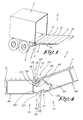
- a truck 1 is represented which is equipped with a loading platform 2 according to the invention.
- this loading platform 2 is fixed at the truck 1 by means of a hinge connection 3.
- driving cylinders which can be controlled by means of a control panel 4
- the loading platform 4 can be lifted and lowered.
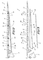
- the loading platform 2 apart from a portion 5 comprising the hinge connection 3, comprises, in this case, five platform parts 6, 7, 8, 9 and 10. Underneath the five platform parts 6-10, at a distance from each other, two hollow reinforcement profiles 11 are attached which, as represented, are closed off preferably by means of a cover 12.
- Figure 3 represents the loading platform 2, whereby the platform parts 6 to 10 thereof, one of the reinforcement profiles 11 and the pertaining cover 12 are dismounted.
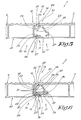
- the edge portions of two successive platform parts, more particularly of the platform parts 7 and 8, are represented in cross-section for different positions, including coupling means 13, by which the platform parts 7-8 are connected.
- These coupling means 13 consist, on one hand, of coupling means which are realized in one piece with the platform parts 7 and 8 and globally are indicated by reference 14, and, on the other hand, one or more securing elements 15.
- the aforementioned coupling parts 14 form a connection between the edges 16 and 17, which are situated against each other, of the platform parts 7 and 8 and are formed by profiled portions 18 and 19 on the upper side of edge 16, the lower side thereof, respectively, as well as profiled portions 20 and 21, on the upper side of edge 17, the lower side thereof, respectively.
- the profiled portion 18 on the upper side of edge 16 of the platform portion 7 consists of laterally protruding lips 22 and 23 which are situated at an interspace and one above the other, the lowermost lip 23 of which comprises an upwardly directed locking portion 24.
- the profiled portion 20 on the upper side of edge 17 of the platform part 8 consists of a lip 25 which fits between the two lips 22 and 23 of the profiled portions 18 and which comprises a downwardly directed locking portion 26 which can cooperate with said upwardly directed locking portion 24.
- the profiled portion 19 at the lower side of the edge 16 of the platform part 7 consists of a laterally protruding lip 27 with a hook-shaped locking portion 28.
- the profiled portion 21 at the lower side of edge 17 of the platform part 8 consists of a laterally protruding lip 29 comprising a hook-shaped locking part 30. Both locking portions 28 and 30 can snap on and engage behind each other, due to the elastic bending of at least one of the aforementioned lips 27 or 29.
- the securing elements 15 comprise locking portions 31 which provide for an engagement behind both edges 16 and 17 of the coupled platform parts 7 and 8, as a result of which a locking in the plane of the loading platform 2 is obtained.
- These locking portions 31 comprise a collar 32 which, in mounted condition, is situated behind a downwardly protruding portion 33 of the lip 23, as well as a protruding portion 34 which cooperates with a transverse wall portion 35 at the height of lip 29.
- the securing element 15 comprises an edge 36 which, in mounted condition, is seated in a recess 37 in the edge 17 of the platform part 8.
- the securing elements 15, as explained in the following, preferably comprise one or more portions which realize a securing effect according to a direction perpendicular to the plane of the loading platform 2.
- One of the lips 27 or 29, lip 27 in the example of the figures is realized thicker or, more generally spoken, more rigid than the other, such that, when snapping on the respective profiled portions 19 and 21 behind each other, the least rigid lip 29 performs an elastic displacement.
- the portion of the securing element 15 which delivers a securing effect according to a direction transverse to the plane of the loading platform 2, consists of a portion which, in mounted condition, prevents the movement of the least rigid lip 29 and, in this case, is formed by the basic body 38 of the securing element 15 and by the collar 32 formed thereon, which are dimensioned such that they are precisely seated between the lip 23 and the elastically bendable lip 29.
- the securing and the locking are performed by means of one and the same securing element 15, however, it is clear that to this end, several securing elements 15 can be used.
- securing element 15 consists of a profile extending over the entire width, or approximately the entire width, of the loading platform 2.
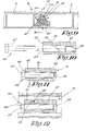
- fixation elements 39 are rivets, more particularly rivets of the type which can be provided by means of blind riveting, however, it is clear that to this end, other fixation elements can be applied as well, such as bolts, screws and the like.
- the reinforcement profiles 11 substantially are U-shaped with an open side 41 which is directed away from the platform parts 6 to 10. In this manner, the rivets or other fixation elements 39 can easily be applied.
- the aforementioned open side 41 of such reinforcement profile 11 is covered by means of the aforementioned cover 12.
- the cover 12 may be omitted, without leaving the scope of the invention.
- such loading platform 2 can easily be composed as follows.
- the platform parts 6 to 10 are coupled laterally to each other by bringing them with their edges 16 and 17 towards each other. Hereby, respectively two successive platform parts 6 to 10 are snapped-on into each other by means of a turning movement.
- the lip 25 of a platform part 7 to 10 respectively becomes situated between the lips 22 and 23 of the preceding platform part 6 to 9, such that the downwardly directed locking portion 26 of the lip 25 and the upwardly directed locking portion 24 of the lip 23 cooperate with each other.
- the hook-shaped locking portion 28 of the lip 27 and the hook-shaped locking portion 30 of the lip 29 snap on, as the less rigid lip 29 is elastically bent by the more rigid lip 27.
- connection is realized between the platform part 6 and the portion 5, which connection can be of any kind.
- the securing elements 15 respectively are slid between two subsequent platform parts 6 to 10. Thereafter, the reinforcement profile 11 is attached against the lower walls 38 of the platform parts 6 to 10, after which, by means of fixation elements 39, the securing elements 15, the platform parts 6 to 10 and the reinforcement profiles 11 are attached to each other. Finally, the covers 12 are provided over the reinforcement profiles 11 and attached thereto, for example, by means of not-represented screws.
- a variant is represented whereby use is made of a securing element 15 which is realized as an expansible element, with which a tensioning force between different portions of the edges 16-17 of the platform parts, in this case, 6-7, can be realized.
- such securing element 15 consists of at least two portions 42-43 and tensioning means 44 with which these portions 42-43 can be drawn towards each other, whereby said two portions 42-43 are provided with contact planes 45-46 which provide for that the portions 42-43, when tensioning the tensioning means 44, are forced away from each other in transverse direction, such as indicated by arrows Z1 and Z2 in figure 11, respectively.
- the tensioning means 44 consist of a bolt 47, the bolt body of which fits freely through a spaciously dimensioned opening 48 in the portion 42 and which engages in the portion 43, in an opening 49 provided with screw thread.
- the platform parts 6 to 10 may, for example, be obtained by extrusion.
- the reinforcement profiles 11 may be manufactured of steel or another material.
Landscapes
- Engineering & Computer Science (AREA)
- Transportation (AREA)
- Mechanical Engineering (AREA)
- Chemical & Material Sciences (AREA)
- Combustion & Propulsion (AREA)
- Body Structure For Vehicles (AREA)
Applications Claiming Priority (2)
| Application Number | Priority Date | Filing Date | Title |
|---|---|---|---|
| IE20010956A IE20010956A1 (en) | 2001-10-25 | 2001-10-25 | Loading Platform for a Truck |
| IE20010956 | 2001-10-25 |
Publications (1)
| Publication Number | Publication Date |
|---|---|
| EP1306265A1 true EP1306265A1 (de) | 2003-05-02 |
Family
ID=11042852
Family Applications (1)
| Application Number | Title | Priority Date | Filing Date |
|---|---|---|---|
| EP02079371A Withdrawn EP1306265A1 (de) | 2001-10-25 | 2002-10-21 | Hebebühne für einen Lastkraftwagen |
Country Status (2)
| Country | Link |
|---|---|
| EP (1) | EP1306265A1 (de) |
| IE (1) | IE20010956A1 (de) |
Cited By (1)
| Publication number | Priority date | Publication date | Assignee | Title |
|---|---|---|---|---|
| EP1621397A1 (de) * | 2004-07-27 | 2006-02-01 | A.V.I. Accessori Veicoli Industriali S.R.L. | Hubladebühne |
Citations (7)
| Publication number | Priority date | Publication date | Assignee | Title |
|---|---|---|---|---|
| US3319543A (en) * | 1965-05-05 | 1967-05-16 | Dow Chemical Co | Structural unit |
| DE1993812U (de) * | 1968-06-19 | 1968-09-12 | Aluminium Walzwerke Singen | Bordwand fuer lastwagenbruecken. |
| DE3538188A1 (de) * | 1985-03-28 | 1986-10-09 | Aluminium-Walzwerke Singen Gmbh, 7700 Singen | Verbundelement aus zwei aneinander festliegenden profilelementen |
| US5664826A (en) * | 1996-04-12 | 1997-09-09 | Wilkens; Arthur L. | Light weight trailer walls with smooth surfaces |
| DE19632725A1 (de) * | 1996-08-03 | 1998-02-05 | Alusuisse Lonza Services Ag | Plattform, insbesondere Ladebordwand für Fahrzeuge |
| DE29917627U1 (de) * | 1999-10-06 | 2000-01-13 | Fa. Otto Fuchs, 58540 Meinerzhagen | Plattform für ein Nutzfahrzeug |
| DE20013693U1 (de) * | 2000-08-09 | 2000-11-23 | Dautel GmbH, 74211 Leingarten | Hubladebühne |
-
2001
- 2001-10-25 IE IE20010956A patent/IE20010956A1/en not_active IP Right Cessation
-
2002
- 2002-10-21 EP EP02079371A patent/EP1306265A1/de not_active Withdrawn
Patent Citations (7)
| Publication number | Priority date | Publication date | Assignee | Title |
|---|---|---|---|---|
| US3319543A (en) * | 1965-05-05 | 1967-05-16 | Dow Chemical Co | Structural unit |
| DE1993812U (de) * | 1968-06-19 | 1968-09-12 | Aluminium Walzwerke Singen | Bordwand fuer lastwagenbruecken. |
| DE3538188A1 (de) * | 1985-03-28 | 1986-10-09 | Aluminium-Walzwerke Singen Gmbh, 7700 Singen | Verbundelement aus zwei aneinander festliegenden profilelementen |
| US5664826A (en) * | 1996-04-12 | 1997-09-09 | Wilkens; Arthur L. | Light weight trailer walls with smooth surfaces |
| DE19632725A1 (de) * | 1996-08-03 | 1998-02-05 | Alusuisse Lonza Services Ag | Plattform, insbesondere Ladebordwand für Fahrzeuge |
| DE29917627U1 (de) * | 1999-10-06 | 2000-01-13 | Fa. Otto Fuchs, 58540 Meinerzhagen | Plattform für ein Nutzfahrzeug |
| DE20013693U1 (de) * | 2000-08-09 | 2000-11-23 | Dautel GmbH, 74211 Leingarten | Hubladebühne |
Cited By (1)
| Publication number | Priority date | Publication date | Assignee | Title |
|---|---|---|---|---|
| EP1621397A1 (de) * | 2004-07-27 | 2006-02-01 | A.V.I. Accessori Veicoli Industriali S.R.L. | Hubladebühne |
Also Published As
| Publication number | Publication date |
|---|---|
| IE20010956A1 (en) | 2003-04-30 |
Similar Documents
| Publication | Publication Date | Title |
|---|---|---|
| CN102442357B (zh) | 加固的车门槛板结构 | |
| US5749407A (en) | Folding garage door with reinforcing struts | |
| MXPA01003651A (es) | Ensambles de pared lateral de seccion delgada para camionetas y remolques. | |
| US7354088B2 (en) | Slidable room assembly and method of installation | |
| US4803821A (en) | Tiled wall structure | |
| US2753018A (en) | Panel assembly | |
| JP5108463B2 (ja) | 鉄道車両の屋根構体構造 | |
| KR100827716B1 (ko) | 고정 브라켓 | |
| GB2047317A (en) | Metal scaffolding boards | |
| EP1306265A1 (de) | Hebebühne für einen Lastkraftwagen | |
| JP6341715B2 (ja) | 折板葺きの屋根構造 | |
| EP1189793A1 (de) | Anschluss für fussbodenbelag in tür- und übergangsbereichen von fahrzeugen, insbesondere schienenfahrzeugen | |
| US20050072053A1 (en) | Seal and molding assembly | |
| GB2378478A (en) | Tiltable shoe for mounting a glazing bar | |
| EP1705327B1 (de) | Tragschiene für Schiebetore | |
| KR20060109341A (ko) | 도어 내측 강판 및 캐리어 요소로 이루어진 조립 유닛 | |
| NL1021799C2 (nl) | Kozijn met afdekprofiel. | |
| RU226648U1 (ru) | Узел крепления грузов магистрального полуприцепа | |
| JP3827689B2 (ja) | 壁パネルの補修構造 | |
| KR200358871Y1 (ko) | 케이블 트레이 커버 체결구조 | |
| JPH08443Y2 (ja) | 組立家屋 | |
| JP2879731B2 (ja) | 荷室構造 | |
| JP2605325Y2 (ja) | サンルーフのフレーム構造 | |
| KR100528159B1 (ko) | 건물의 천정판 지지구조 | |
| JPH046461Y2 (de) |
Legal Events
| Date | Code | Title | Description |
|---|---|---|---|
| PUAI | Public reference made under article 153(3) epc to a published international application that has entered the european phase |
Free format text: ORIGINAL CODE: 0009012 |
|
| AK | Designated contracting states |
Designated state(s): AT BE BG CH CY CZ DE DK EE ES FI FR GB GR IE IT LI LU MC NL PT SE SK TR |
|
| AX | Request for extension of the european patent |
Extension state: AL LT LV MK RO SI |
|
| 17P | Request for examination filed |
Effective date: 20030905 |
|
| AKX | Designation fees paid |
Designated state(s): AT BE BG CH CY CZ DE DK EE ES FI FR GB GR IE IT LI LU MC NL PT SE SK TR |
|
| STAA | Information on the status of an ep patent application or granted ep patent |
Free format text: STATUS: THE APPLICATION IS DEEMED TO BE WITHDRAWN |
|
| 18D | Application deemed to be withdrawn |
Effective date: 20050503 |