EP1306479A2 - Machine à laver - Google Patents
Machine à laver Download PDFInfo
- Publication number
- EP1306479A2 EP1306479A2 EP02023820A EP02023820A EP1306479A2 EP 1306479 A2 EP1306479 A2 EP 1306479A2 EP 02023820 A EP02023820 A EP 02023820A EP 02023820 A EP02023820 A EP 02023820A EP 1306479 A2 EP1306479 A2 EP 1306479A2
- Authority
- EP
- European Patent Office
- Prior art keywords
- washing machine
- washing
- machine according
- drum
- laundry
- Prior art date
- Legal status (The legal status is an assumption and is not a legal conclusion. Google has not performed a legal analysis and makes no representation as to the accuracy of the status listed.)
- Granted
Links
Images





Classifications
-
- D—TEXTILES; PAPER
- D06—TREATMENT OF TEXTILES OR THE LIKE; LAUNDERING; FLEXIBLE MATERIALS NOT OTHERWISE PROVIDED FOR
- D06F—LAUNDERING, DRYING, IRONING, PRESSING OR FOLDING TEXTILE ARTICLES
- D06F37/00—Details specific to washing machines covered by groups D06F21/00 - D06F25/00
- D06F37/02—Rotary receptacles, e.g. drums
- D06F37/04—Rotary receptacles, e.g. drums adapted for rotation or oscillation about a horizontal or inclined axis
- D06F37/06—Ribs, lifters, or rubbing means forming part of the receptacle
Definitions
- This invention relates to washing machines. More particularly, it relates to washing machines having improved washing performance and easier laundry removal.
- Washing machines operate by revolving a vessel that holds laundry, water, and detergent such that friction, water current, and chemical action clean the laundry. While there are various types of washing machines, common types include drum type washing machines and pulsator type washing machines.
- a drum washing machine includes a cabinet 1 having a front door 2, a tub 3 inside the cabinet 1 that retains wash water, and a rotating drum 4 inside the tub 3 that retains laundry.
- a motor 5 behind the tub 3 is coupled by a driving shaft 6 to the drum 4.
- a suspension system 7 retains the tub 3 within the cabinet 1 such that the position of the tub 3 can fluctuate slightly.
- the driving shaft 6 is coupled to the drum 4 by a spider 8 (which can be tripod-shaped). Additionally, as shown, a number of lifters 10 are mounted on a wall of the drum 4. When the motor 5 rotates the drum 4, the lifters 10 also rotate. Laundry is lifted upward by the lifters 10 until the laundry freely falls down. Continuous rotation causes the laundry to continuously move up and down. Such laundry movement produces a good laundry cleaning action.
- FIG. 2 illustrates a typical lifter 10 in more detail.
- the lifter 10 includes a pair of protrusions 11 that have different heights and that are separated by a valley 12. Coupling hooks 13 at the bottom of the lifter 10 can couple the lifter 10 to the drum 4.
- the lifters 10 While generally successful, the lifters 10 do not provide optimal washing performance. One reason for this is that the lifters 10 generally have flat (or at least smooth) surfaces that fail to maximize laundry friction. Thus, friction-induced cleaning is limited. Such limited cleaning action occurs not only in drum type washing machines, but also in pulsator type washing machines. The pulsator type cleans both by water flow and by laundry friction. Yet, the widely used pulsator type washing machine also uses generally flat (or at least smooth) contact surfaces. Again, this limits the attainable cleaning action.
- a modification to the standard drum type washing machine is the slant-drum washing machine.
- the drum 4 In such a machine the drum 4 is tilted downward. This reduces the difficulty of inserting and removing laundry.
- the laundry tends to gather toward the rear of the drum 4 such that the lifters 10 fail to smoothly move the laundry. Thus, cleaning performance is reduced.
- washing machines having improved washing performance obtained by increasing the friction of lifters with laundry would be beneficial. Also beneficial would be a washing machine having easy laundry removal after dehydration cycles. Also beneficial would be a slant-drum washing machine having a reduced tendency for laundry to congregate at the back of the drum. Even more beneficial would be a drum washing machine with improved laundry friction and ease of laundry removal.
- the present invention is directed to a washing machine that substantially obviates one or more problems due to limitations and disadvantages of the related art.
- An object of the present invention is to provide a washing machine with improved washing performance caused by increased laundry friction.
- Another object of the present invention is to provide a washing machine enabling easy laundry removal after dehydration.
- Another object of the present invention is to provide a slant-drum washing machine having a reduced tendency to congregate laundry at the rear of the drum.
- a washing machine includes a cabinet having a door and a rotatable internal vessel inside the cabinet for retaining laundry.
- the internal vessel which is coupled with a motor, can be located within a water-retaining vessel.
- a friction member inside the internal vessel generates water current when the internal vessel is rotated.
- a friction enhancer which is part of the friction member, increases the friction between the friction member and the laundry.
- the friction member is a lifter, when the washing machine is a drum or a slant-drum type washing machine, or a pulsator when the washing machine is a pulsator type washing machine.
- the friction enhancer includes washing protrusions or washing balls that protrude from the friction member toward the middle of the internal vessel.
- a washing machine in another aspect of the present invention, includes a cabinet having a front door, a tub inside the cabinet that retains wash water and that includes an opening that confronts the door.
- a drum located inside the tub, is coupled with a driving part (such as by a shaft) that rotates the drum.
- Lifters inside the drum protrude toward the center of the drum. As the drum rotates, the lifters move the laundry upward until the laundry freely falls downward. Friction between the laundry and the lifters help clean the laundry.
- the lifters include friction enhancers, such as protrusions or washing balls, that increase the friction between the lifters and the laundry, thus improving cleaning. Additionally, the friction enhancers reduce adhesion between the laundry and the drum/lifters after a dehydration cycle, which makes the laundry easier to remove.
- a washing machine includes a cabinet having a door, a water storage vessel (tub) inside the cabinet for retaining water, and a rotating laundry vessel (drum) inside the water storage vessel for holding laundry.
- the laundry vessel is coupled to a driving part (motor) that rotates the laundry vessel.
- the washing machine further includes a friction member inside the laundry vessel that produces water current and that contacts (rubs) laundry in the laundry vessel so as to induce cleaning.
- the friction member includes a friction enhancer that increases laundry friction.
- the friction enhancer can include washing protrusions that protrude inward from the friction member.
- the friction enhancer can include washing balls that protrude inward.
- the friction enhancers increase cleaning friction with the laundry. Additionally, the friction enhancers reduce the difficulty of removing laundry from the washing machine.
- the friction member is either a pulsator or a lifter, depending on the type of washing machine. Namely, a pulsator type washing machine uses a pulsator, while a drum type washing machine uses a lifter.
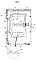
- FIG. 3 illustrates a sectional view of a drum type washing machine according to a first embodiment of the present invention.
- FIG. 3 includes a magnified sectional view of a portion of a lifter.
- a washing machine according to a first embodiment includes a cabinet 21 having a front door 22, and a tub 23 inside the cabinet 21 that includes an opening 23a that confronts the door 22. Inside the tub 23 is a rotating drum 24. The tub 23 retains wash water, while the drum 24 retains laundry.
- a driving part 25 (motor) behind the tub 23 is coupled to the drum 24 by a driving shaft 26. The driving part 25 (motor) induces a rotational force that turns the drum 24.
- the drum 24 is parallel with the tub 23, which, in turn, is parallel with the ground.
- each lifter 100 includes a plurality of washing protrusions 120 that protrude into the drum 24 from protruding faces 110.
- the washing protrusions 120 increase the contact area of the lifter 100 with the laundry, and thus act as friction enhancers.
- the washing protrusions 120 may be integral features of the lifters 100, or they may be discrete elements that are coupled with the protruding faces 110.
- the washing protrusions 120 are beneficially hemispherical. This reduces laundry damage while increasing laundry friction.
- the washing protrusions 120 also reduce adhesion between the laundry and the lifters 100 following a dehydration cycle. This is because the centrifugal forces that push the laundry against the drum wall during the dehydration cycle will seldom be sufficient to eliminate all spaces between the lifters 100 and the laundry. Such spaces significantly reduce the adherence of the laundry to the lifters 100, making the laundry easier to remove.
- washing protrusions 120 do not have to be hemispherical. Other shapes can increase the laundry contact area while leaving spaces between the lifters 100 and the laundry.
- the lifters 100 include a number of drain holes 130.
- the drain holes 130 are formed through the washing protrusions 120.
- the drain holes 130 enable wash water to flow between the lifters 100 and the drum 24. Wash water that has flowed through the drain holes 130 to the lifters 100 is free to fall as the lifters 100 rotate. The falling wash water soaks and impacts the laundry, thus improve washing.
- the operation of the first embodiment washing machine is as follows. First, a user selects a proper washing sequence through a control panel 29. With laundry and soap in the drum 24, the drum 24 is supplied with wash water through a supply pipe. After the correct amount of water is added, electric power is applied to the driving part 25 (motor), which then turns the drum 24. As the drum 24 rotates, the lifters 100 lift the wash water and laundry until they fall free. Significantly, the washing protrusions 120 increase the frictional forces against the laundry. Additionally, wash water flows into the lifters 100 as they dip into the wash water. As the lifters 100 rotate upward the wash water in the lifters drops through the drain holes 130, impacting on the laundry, and improving performance. The process is vigorously repeated to rub the laundry, thereby carrying out cleaning. Subsequently, rinsing and dehydration cycles are performed. Water falling from the drain holes 130 also improves rinsing during the rinsing cycles.
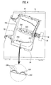
- FIG. 4 illustrates a sectional view of a slant type washing machine according to a second embodiment of the present invention.
- FIG. 4 also includes a magnified view of a portion of a lifter.
- a washing machine according to the second embodiment is a slant-drum type washing machine. That machine includes a cabinet 31 having a door 22 at a slanted face. A tub 33 inside the cabinet retains wash water. The tub 33 includes an opening 33a that confronts the door 32. Inside the tub 33 is a drum 34. A driving part 35 (motor) located behind the tub 33 is coupled to the drum 34 by a driving shaft 36. The tub 33 is installed at an incline such that the front of the tub 33 (having the opening 33a) is higher than the rear.
- a number of lifters 200 are installed on a wall of the drum 34. Those lifters 200, which inwardly protrude toward the rotational axis of the drum 34, are elongated along the rotational axis.
- the lifters 200 each have washing protrusions 220 on protruding faces 210. Beneficially, the washing protrusions 220 are hemispherical.
- the lifters 200 each include a number of drain holes 230 through the washing protrusions 220.
- the second embodiment enables improved washing by providing increased friction between the washing protrusions 220 and the laundry, and by providing free falling wash water through the drain holes 230.
- the washing protrusions (220) reduce adhesion between the laundry and the lifters 200, thereby enabling easy removal of laundry from the washing machine.
- the height of the lifters 200 increases from the front of the drum 34 to the rear. This compensates for the inclination of the tub 33 and the drum 34 so that the protruding faces 210 of the lifters 200 are more parallel with the ground. This reduces the tendency for laundry to concentrate at the rear of the drum 34. Furthermore, even if laundry does concentrate at the rear, the shape of the lifters 200 tends to move the laundry forward. Thus, the lifters 200 act to distribute the laundry evenly in the drum 34. This also tends to improve washing performance.
- FIG. 5 illustrates a cross-sectional view of a drum type washing machine according to a third embodiment of the present invention.
- the third embodiment drum type washing machine is very similar to the first embodiment washing machine, the following is specifically directed at the lifters 300 (which are different).
- a number of lifters 300 are installed on the wall of the drum 24. Those lifters 300 each beneficially extend parallel to the axis of the drum 24 and protrude from the drum wall toward the center of the drum 24.
- Each lifter 300 includes a number of washing balls 320 that protrude from faces of the lifters 300.
- the washing balls 320 act as friction enhancing devices. The washing balls 320 rotate in the lifters 300 by the friction with the laundry.
- FIG. 6 illustrates a cross-sectional view of a lifter 300.
- each lifter 300 includes a lifter body 310 that is coupled to the wall of the drum 24.
- a ball support structure 330 is installed inside the lifter body 310.
- the ball support structure 330 supports, retains, and separates the washing balls 320 such that they are free to rotate in ball sockets 315.
- the ball sockets 315 are formed such that a portion of each washing ball 320 extends from the lifter body 310. In practice the diameter of the washing balls 320 should be such that they do not fall into the drum 24 or lifter 300.
- the ball support structure 330 takes the form of a platelike support cover that is coupled with the rear of a protruding face 311 of the lifter body 310.
- a plurality of locking bosses 317 is formed at the protruding face 311.
- a plurality of locking grooves 337 is formed at a support cover 330 in positions that correspond to the locking bosses 317. Therefore, the support cover 330 can be coupled with the lifter body 310 by locking bolts 319.
- a plurality of support grooves 335 are formed in the support cover 330 at positions that correspond to the washing ball sockets 315 so as to enable the washing balls 320 to rotate.
- Each of the support grooves 335 is beneficially concave so as to correspond to the curvature of the washing balls 320.
- auxiliary protrusions 325 can be formed on the washing balls 320.
- the auxiliary protrusions 325 induce greater friction with the laundry. This enables improved washing performance.
- the auxiliary protrusions 325 are preferably formed so as to define the angle through which the washing balls 320 can rotate.
- the lifters 300 move laundry as the drum 24 rotates during washing and rinsing cycles.
- the washing balls 320 rotate in the washing ball sockets 315 and the support groves 335 due to laundry friction.
- the washing balls 320 increase the friction area between the lifters 300 and the laundry, producing vigorous cleaning. If present, the auxiliary protrusions 325 increase laundry friction even more, thereby improving laundry performance.
- centrifugal forces produced by the rotation of the drum 24 during a dehydration cycle cause the laundry to be forced toward the wall of the drum 24 and the lifters 300.
- the washing balls 320 induce gaps between the lifter body 310 and the laundry, thereby reducing the difficulty of removing the laundry from the washing machine. Furthermore, since the washing balls 320 can rotate, separating the laundry from the lifters 300 is even easier.
- the auxiliary protrusions 325 further reduce adhesion between the laundry and the lifters 300. Therefore, after dehydration, the laundry is withdrawn with less difficulty.
- FIG. 7 illustrates a cross-sectional view of a slant-drum washing machine according to a fourth embodiment of the present invention.
- the fourth embodiment is very similar to the second embodiment, only the lifters (which are different) are discussed in detail.
- a plurality of lifters 400 is installed on the wall of a slant drum 34. Those lifters 400 extend along the axis of rotation of the drum 34 and protrude toward the center of the drum 34.
- a plurality of washing balls 420 are installed at protruding faces of the lifters 400. The washing balls 420 are free to rotate when contacted by laundry.
- Each lifter 400 is formed to have a gradually increasing height as one proceeds from the front to the rear. This causes the protruding face of the lifter 400 to be substantially parallel to the ground.
- FIG. 8 illustrates a cross-sectional view of a lifter 400 used in the slant type washing machine of FIG. 7. That lifter is similar to that shown in FIG. 6.
- each lifter 400 includes a lifter body 410 that is coupled with a wall of the drum 34, and a support cover 430 that is installed inside the lifter body 410 so as to support and retain the washing balls 420 such that they can rotate.
- a plurality of washing ball sockets 415 are formed at protruding faces 411 of the lifter body 410, and support grooves 435 are formed in the support cover 430 at positions that correspond to the washing ball sockets 415.
- a plurality of optional auxiliary protrusions 425 is formed on each washing ball 420.
- locking bosses 417 and locking bolts 419 are used to couple the support cover 430 with the lifter body 410.
- the protruding height of the lifter body 410 at the rear of the drum 34 is greater than at the front. Therefore, the lifters 400 reduce the tendency of the laundry to concentrate at the rear of the drum 34. Even if laundry does concentrate toward the rear, the lifters 400 reduce the difficulty of removing laundry.
- FIG. 9 illustrates a cross-sectional view of a lifter 500 that is used in a drum type washing machine according to a fifth embodiment of the present invention. As the fifth embodiment is similar to the first embodiment (see FIG. 3), only the lifters 500 are discussed in detail.
- a plurality of washing balls 520 are installed at protruding faces 511 of each lifter 500.
- the washing balls 520 are rotatable and protrude from the lifter 500 so as to increase laundry friction.
- Each lifter 500 is coupled with a wall of a drum and is elongated along the axis of rotation of the drum.
- Each lifter 500 includes a lifter body 510 that protrudes from the drum wall toward the center of the drum.
- a support means 530 inside the lifter body 510 supports the washing balls 520 such that the washing balls can rotate.
- FIG. 10 illustrates a detailed diagram of section A illustrated in FIG. 9.
- a washing ball 520 passes through an insertion hole 515 in the protruding face 511 of the lifter body 510. A portion of the washing ball 520 is thus exposed in the drum.
- the diameter of the washing ball 520 is somewhat greater than the diameter of the insertion hole 515.
- the support protrusions 530 extend into the lifter body 510 near the insertion hole 515.
- Each washing ball 520 is beneficially shaft-coupled with support protrusions 530 that are installed around the washing balls 520 by a rotational shaft 521.
- Holding sills 531 are located at ends of the support protrusions 530 so as to retain the rotational shafts 521.
- FIG. 11 illustrates the coupling relationship between the washing balls 520, the rotational shafts 521, the support protrusions 530, and the holding sills in more detail.
- the holding sills 531 are at ends of pairs of support protrusions 530.
- the rotational shaft 521 is located in the holding sills 531 (such as by pressing the rotation shaft to force the holding sills 531 apart) such that the washing balls 520 can rotate.
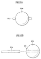
- FIG. 12A and FIG. 12B illustrate washing balls 520a and 520b that are suitable for use in the structure of FIG. 9.
- rotational shafts 521a extend from a washing ball 520a so as to define a centerline of the washing ball 520a.
- a rotational shaft 521b passes through a penetrating hole 523 through the center of a washing ball 520b.
- the lifter body 510 further includes a curved surface 511 that directs laundry to the center of the drum.
- a friction part 512 increases the coupling adherence of the lifter 500 to the drum.
- a locking part 513 provides the actual coupling force.
- the curved surface 511 forms a protruding face having the washing ball insertion holes 515.
- the protruding height of the curved part 511 increases from the front to the rear of the lifter 500.
- the lifter body 510 tends to move laundry toward the center of the drum, thereby improving washing performance.
- the friction part 512 also has a curved surface, thereby enabling the lifter body 510 to adhere more closely with the drum.
- the locking part 513 is located at a concave portion at the rear of the lifter body 510.
- a bracket 541 and a finishing member 542 are inserted, in order, into the concave portion.
- a locking bolt 543 penetrates the drum, finishing member 542, and bracket 541 such that the lifter body 510 is fastened to the drum.
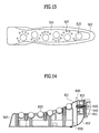
- FIG. 13 illustrates a specific configuration of a lifter body 510 that is suitable for use in the lifter of FIG. 9.
- the lifter body 510 has convex portions along a streamlined, elongated shape. Additionally, the lifter body 510 is gradually tapered from the bottom to the curved surface part 511. This reduces drag with the washing water. Furthermore, a plurality of drain holes 517 is formed through the curved surface 511. The drain holes 517 enable the wash water to freely flow between the lifter 500 and the drum, thereby improving the washing performance more greatly.
- FIG. 14 illustrates a cross-sectional view of a lifter 600 in a drum type washing machine according to a sixth embodiment of the present invention.
- the lifters 600 include a plurality of washing balls 620 that extend from a protruding face 611. The washing balls 620, which are free to rotate, increase friction between the lifter 600 and laundry.
- the lifters 600 are coupled with the wall of drum.
- the lifters 600 are elongated along a shaft direction.
- Each lifter includes a lifter body 610 that has a predetermined profile such that the lifter body is higher at the rear than at the front.
- a ball housing 630 inside the lifter body 610 supports the washing balls 620 such that the washing balls 620 can rotate.
- FIG. 15 illustrates a cross-sectional view of a lifter body 610 and a ball housing 630 that are suitable for use in the embodiment of FIG. 14.
- a plurality of washing ball insertion holes 615 are formed along the protruding face 611 of the lifter body 610.
- the washing ball insertion holes 615 are fabricated such that portions of the washing balls 620 are exposed inside the drum.
- a plurality of support grooves 635 is formed in an upper face of the ball housing 630 such that the washing balls 620 can rotate. When assembled, the washing ball insertion holes 615 and support grooves 635 are positioned so as to confront each other. The washing balls 620 rotate in a space between the washing ball insertion holes 615 and the support grooves 635.
- the lifter body 610 includes a locking portion 613.
- a bracket 641 and a finishing member 642 are inserted, in order, into the locking portion 613.
- a locking bolt 643 penetrates the drum, the finishing member 642, and the bracket 641 such that the lifter body 610 is fastened to the drum.
- the lifter body 610 has a streamlined shape similar to that of the lifter body 510 (see above) and thus includes convex portions along its length.
- the washing ball insertion holes 615 differ in height such that the ones in the rear are higher than the one in the front.
- the ball housing 631 is preferably formed with steps.
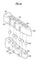
- FIG. 16 shows how a ball housing 630 is coupled with the lifter body 610 using a fit system such that the washing balls 620 are disposed between the lifter body 610 and the ball housing 630.
- a plurality of locking slots 619 is formed in a coupling face of the lifter body 610, and a corresponding plurality of locking protrusions 639 are formed at a coupling face of the ball housing 630.
- the locking slots 619 and locking protrusions 639 are vertically formed with matching rectangular cross-sections.
- the locking slots 619 are relieved to receive ribs that retain the locking protrusions 639 to the ball housing 630 (the ribs have T-cross-sections). Therefore, when the ball housing 630 is mated inside the lifter body 610, the locking protrusions 639 slide into the locking slots 619 so as to fix the ball housing 630 to the lifter body 610.
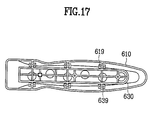
- FIG. 17 illustrates a bottom view of a lifter 600 according to FIG. 14.
- FIG. 17 shows the fit between the locking slots and protrusions 619 and 639.
- the lifter body 610 includes a plurality of drain holes 617 through the curved surface 611.
- the drain holes 617 have the same function as the previously described drain holes.
- the operation of the lifter 600 in a washing machine according to the sixth embodiment is similar to that of the third embodiment. Therefore, a detailed description will not be specifically provided.
- the present invention has various advantages.
- the friction enhancers such as washing protrusions and washing balls, improve laundry friction, thereby improving washing performance.
- the friction enhancers reduce adherence of laundry to the lifters, thereby reducing the difficulty of removing laundry.
- the protruding height of the lifters in slant-drum washing machine the tendency of laundry to congregate at the rear of the drum is reduced, thus enabling a more even distribution of laundry in the drum, which improves washing performance and which reduces the difficulty of removing laundry.
- the invention relates to washing machines having improved frictional forces with laundry.
- Those machines include a cabinet with a door, a tub inside the cabinet for retaining wash water, and an internal vessel inside the tub that is coupled with a motor that rotates the internal vessel.
- a friction member inside the internal vessel rubs against laundry.
- the frictional member includes a friction enhancer, such as a spherical structure or a freely rotating ball, that enhances laundry friction during washing and reduces adhesion of laundry after a dehydration cycle.
Landscapes
- Engineering & Computer Science (AREA)
- Textile Engineering (AREA)
- Main Body Construction Of Washing Machines And Laundry Dryers (AREA)
- Accessory Of Washing/Drying Machine, Commercial Washing/Drying Machine, Other Washing/Drying Machine (AREA)
Applications Claiming Priority (8)
| Application Number | Priority Date | Filing Date | Title |
|---|---|---|---|
| KR2001065458 | 2001-10-23 | ||
| KR1020010065458A KR100797463B1 (ko) | 2001-10-23 | 2001-10-23 | 드럼세탁기의 리프터 |
| KR1020010065459A KR100765273B1 (ko) | 2001-10-23 | 2001-10-23 | 드럼세탁기의 리프터 |
| KR2001065459 | 2001-10-23 | ||
| KR10-2002-0001293A KR100465689B1 (ko) | 2002-01-09 | 2002-01-09 | 드럼 세탁기의 리프터 |
| KR2002001292 | 2002-01-09 | ||
| KR10-2002-0001292A KR100452352B1 (ko) | 2002-01-09 | 2002-01-09 | 드럼 세탁기의 리프터 |
| KR2002001293 | 2002-01-09 |
Publications (3)
| Publication Number | Publication Date |
|---|---|
| EP1306479A2 true EP1306479A2 (fr) | 2003-05-02 |
| EP1306479A3 EP1306479A3 (fr) | 2003-10-22 |
| EP1306479B1 EP1306479B1 (fr) | 2006-12-13 |
Family
ID=27483533
Family Applications (1)
| Application Number | Title | Priority Date | Filing Date |
|---|---|---|---|
| EP02023820A Expired - Lifetime EP1306479B1 (fr) | 2001-10-23 | 2002-10-23 | Machine à laver |
Country Status (6)
| Country | Link |
|---|---|
| US (1) | US7096695B2 (fr) |
| EP (1) | EP1306479B1 (fr) |
| JP (1) | JP3772821B2 (fr) |
| CN (1) | CN1201043C (fr) |
| AU (1) | AU2002301489B2 (fr) |
| DE (1) | DE60216699T2 (fr) |
Cited By (14)
| Publication number | Priority date | Publication date | Assignee | Title |
|---|---|---|---|---|
| EP1502982A2 (fr) | 2003-07-28 | 2005-02-02 | Lg Electronics Inc. | Machine à laver |
| WO2006126814A3 (fr) * | 2005-05-23 | 2007-02-22 | Lg Electronics Inc | Lave-linge de type a tambour et methode de fabrication du tambour correspondant |
| DE102005032045B4 (de) * | 2004-07-08 | 2007-11-22 | Lg Electronics Inc. | Trommelwaschmaschine |
| WO2008000593A1 (fr) * | 2006-06-27 | 2008-01-03 | BSH Bosch und Siemens Hausgeräte GmbH | Système modulaire pour des tambours à linge d'appareils d'entretien du linge |
| WO2009109526A1 (fr) * | 2008-03-03 | 2009-09-11 | BSH Bosch und Siemens Hausgeräte GmbH | Tambour de machine à laver |
| US7690227B2 (en) | 2005-06-30 | 2010-04-06 | Lg Electronics Inc. | Drum type washer |
| EP2476790A1 (fr) * | 2011-01-16 | 2012-07-18 | Samsung Electronics Co., Ltd | Machine à laver et son pulsateur |
| EP2339060A4 (fr) * | 2008-08-28 | 2013-03-13 | Daewoo Electronics Corp | Séchoir équipé d'un dispositif de levage hybride |
| DE102007027547B4 (de) * | 2006-06-15 | 2013-03-28 | Lg Electronics Inc. | Waschmaschine |
| EP3190220A3 (fr) * | 2016-01-05 | 2017-09-27 | Lg Electronics Inc. | Dispositif de levage pour appareil de traitement de linge |
| EP3690108A1 (fr) * | 2019-02-01 | 2020-08-05 | LG Electronics Inc. -1- | Appareil de traitement du linge |
| EP3875664A1 (fr) * | 2020-03-06 | 2021-09-08 | LG Electronics Inc. | Appareil de traitement du linge |
| US11268229B2 (en) | 2019-02-01 | 2022-03-08 | Lg Electronics Inc. | Laundry treating apparatus |
| US11414802B2 (en) | 2019-02-01 | 2022-08-16 | Lg Electronics Inc. | Laundry treating apparatus |
Families Citing this family (55)
| Publication number | Priority date | Publication date | Assignee | Title |
|---|---|---|---|---|
| KR100451747B1 (ko) * | 2002-09-25 | 2004-10-08 | 엘지전자 주식회사 | 드럼세탁기의 리프트 |
| KR100465724B1 (ko) * | 2002-12-26 | 2005-01-13 | 엘지전자 주식회사 | 드럼세탁기의 리프트 |
| KR100464054B1 (ko) | 2002-12-27 | 2005-01-03 | 엘지전자 주식회사 | 일체형 캐비넷/터브를 구비한 드럼 세탁기 |
| EP2305874B1 (fr) | 2002-12-27 | 2017-08-23 | LG Electronics Inc. | Machine à laver à tambour |
| JP2005000480A (ja) * | 2003-06-13 | 2005-01-06 | Sharp Corp | 洗濯乾燥機 |
| US7627960B2 (en) * | 2003-06-30 | 2009-12-08 | General Electric Company | Clothes dryer drum projections |
| KR20050006328A (ko) * | 2003-07-08 | 2005-01-17 | 엘지전자 주식회사 | 드럼세탁기 |
| KR20050045256A (ko) * | 2003-11-10 | 2005-05-17 | 삼성전자주식회사 | 드럼세탁기 |
| EP1529866A1 (fr) * | 2003-11-10 | 2005-05-11 | Samsung Electronics Co., Ltd. | Machine à laver à tambour |
| US20050132755A1 (en) * | 2003-12-18 | 2005-06-23 | General Electric Company | Apparatus for reducing retained moisture content of articles and method of fabricating |
| US20050204785A1 (en) * | 2004-03-19 | 2005-09-22 | Lg Electronics Inc. | Drum-type washing machine |
| US7299665B2 (en) * | 2004-03-19 | 2007-11-27 | Lg Electronics Inc. | Lift for drum-type washing machine |
| KR101054408B1 (ko) * | 2004-04-19 | 2011-08-05 | 엘지전자 주식회사 | 세탁기 |
| KR100634802B1 (ko) | 2004-07-20 | 2006-10-16 | 엘지전자 주식회사 | 드럼 세탁기 |
| JP4419750B2 (ja) * | 2004-08-17 | 2010-02-24 | パナソニック株式会社 | ドラム式洗濯機または洗濯乾燥機 |
| DE102004043716A1 (de) * | 2004-09-09 | 2006-03-16 | BSH Bosch und Siemens Hausgeräte GmbH | Verfahren zum Befestigung von Kunststoffmitnehmern in Wäschetrommeln |
| JP4301128B2 (ja) * | 2004-09-13 | 2009-07-22 | パナソニック株式会社 | ドラム式洗濯機 |
| KR100686017B1 (ko) * | 2005-05-11 | 2007-02-26 | 엘지전자 주식회사 | 세탁기 |
| KR101275198B1 (ko) | 2005-05-23 | 2013-06-18 | 엘지전자 주식회사 | 드럼세탁기 및 그에 적용되는 드럼 제조방법 |
| US7841220B2 (en) | 2005-09-30 | 2010-11-30 | Lg Electronics Inc. | Drum-type washing machine |
| KR100664290B1 (ko) | 2006-02-27 | 2007-01-04 | 엘지전자 주식회사 | 의류 건조기의 건조 드럼 |
| US7536882B2 (en) | 2006-03-29 | 2009-05-26 | Lg Electronics Inc. | Drum type washing machine |
| EP1876280B1 (fr) * | 2006-07-06 | 2010-09-22 | Candy S.p.A. | Tambour pour lave-linge, sèche-linge et similaires |
| JP4652306B2 (ja) * | 2006-09-27 | 2011-03-16 | パナソニック株式会社 | 洗濯機 |
| KR100808204B1 (ko) * | 2007-04-10 | 2008-03-03 | 엘지전자 주식회사 | 드럼세탁기 |
| KR20080095502A (ko) * | 2007-04-24 | 2008-10-29 | 삼성전자주식회사 | 드럼세탁기 및 이를 이용한 세탁방법 |
| KR101367112B1 (ko) | 2007-06-07 | 2014-02-26 | 삼성전자주식회사 | 회전조 바디와 이를 갖춘 드럼세탁기 |
| DE102007028213A1 (de) * | 2007-06-20 | 2008-12-24 | BSH Bosch und Siemens Hausgeräte GmbH | Waschmaschine und Verfahren zur Behandlung von Wäsche mit Schaum |
| KR200464409Y1 (ko) | 2007-09-17 | 2013-01-02 | 삼성전자주식회사 | 드럼세탁기 |
| EP2372010B1 (fr) * | 2010-04-01 | 2016-09-21 | Electrolux Home Products Corporation N.V. | Tambour rotatif pour machines à laver et procédé d'assemblage du tambour rotatif |
| JP5147088B2 (ja) * | 2010-07-27 | 2013-02-20 | 株式会社ハッピー | 洗濯装置 |
| US8701451B2 (en) | 2010-12-08 | 2014-04-22 | Whirlpool Corporation | Laundry treating appliance with balancing system |
| US8713977B2 (en) | 2010-12-08 | 2014-05-06 | Whirlpool Corporation | Laundry treating appliance with balancing system |
| US8991223B2 (en) | 2010-12-08 | 2015-03-31 | Whirlpool Corporation | Laundry treating appliance with balancing system |
| US8695383B2 (en) | 2010-12-08 | 2014-04-15 | Whirlpool Corporation | Laundry treating appliance with balancing system |
| US9003838B2 (en) | 2010-12-08 | 2015-04-14 | Whirlpool Corporation | Laundry treating appliance with balancing system |
| USD664727S1 (en) * | 2011-10-06 | 2012-07-31 | Samsung Electronics Co., Ltd. | Lifter for washing machine |
| JP6050633B2 (ja) * | 2012-08-10 | 2016-12-21 | シャープ株式会社 | 洗濯機 |
| KR101715768B1 (ko) * | 2014-07-09 | 2017-03-13 | 동부대우전자 주식회사 | 세탁장치 및 방법 |
| KR101696898B1 (ko) * | 2014-07-09 | 2017-01-16 | 동부대우전자 주식회사 | 세탁 장치 및 세탁 방법 |
| CN105696248B (zh) * | 2014-11-27 | 2019-08-20 | 青岛海尔滚筒洗衣机有限公司 | 一种节水滚筒洗衣机 |
| KR102557928B1 (ko) * | 2016-08-04 | 2023-07-21 | 삼성전자주식회사 | 리프터 및 이를 가지는 세탁기 |
| US10767301B2 (en) * | 2017-02-24 | 2020-09-08 | Talar Terzian | Spin cycle mobile washer |
| CN107675433A (zh) * | 2017-11-29 | 2018-02-09 | 鹿寨卡森洗涤服务有限公司 | 洗衣机用衣物护理支架 |
| EP3690106B1 (fr) | 2019-02-01 | 2021-03-31 | LG Electronics Inc. | Appareil de traitement du linge |
| KR20200096048A (ko) * | 2019-02-01 | 2020-08-11 | 엘지전자 주식회사 | 세탁물 처리기기 |
| KR102810496B1 (ko) * | 2019-02-01 | 2025-05-23 | 엘지전자 주식회사 | 세탁물 처리기기 |
| KR102789565B1 (ko) | 2019-02-01 | 2025-04-01 | 엘지전자 주식회사 | 세탁물 처리기기 |
| EP3690105B1 (fr) | 2019-02-01 | 2021-03-10 | LG Electronics Inc. | Appareil de traitement du linge |
| EP3690107A1 (fr) * | 2019-02-01 | 2020-08-05 | LG Electronics Inc. -1- | Appareil de traitement du linge |
| CN112391786A (zh) * | 2019-08-19 | 2021-02-23 | 青岛海尔滚筒洗衣机有限公司 | 一种洗衣机 |
| KR102491392B1 (ko) * | 2020-03-06 | 2023-01-27 | 엘지전자 주식회사 | 세탁물 처리기기 |
| KR102422407B1 (ko) * | 2020-03-06 | 2022-07-18 | 엘지전자 주식회사 | 세탁물 처리기기 |
| CN115679628B (zh) * | 2021-07-21 | 2026-03-20 | 合肥海尔洗衣机有限公司 | 一种洗衣机的洁桶装置及洗衣机 |
| CN116084136A (zh) * | 2021-11-08 | 2023-05-09 | 无锡小天鹅电器有限公司 | 一种搓洗机构及衣物处理设备 |
Family Cites Families (14)
| Publication number | Priority date | Publication date | Assignee | Title |
|---|---|---|---|---|
| US408797A (en) * | 1889-08-13 | Washing-machine | ||
| US1389182A (en) | 1920-03-31 | 1921-08-30 | Binder Gottlob | Rotary washing-machine |
| DE537758C (de) | 1930-10-15 | 1931-11-06 | Simon Mook | Waschmaschine |
| US2480929A (en) * | 1947-12-30 | 1949-09-06 | Sam M Hyman | Button protector pad for drying machines |
| SE351878B (fr) * | 1971-08-23 | 1972-12-11 | Ctc Ab | |
| SE359584B (fr) * | 1972-01-14 | 1973-09-03 | Z Horowitz | |
| JPS5125970B2 (fr) | 1972-10-21 | 1976-08-03 | ||
| US4546625A (en) * | 1984-07-30 | 1985-10-15 | Norrell William L | Dry cleaning machine |
| SU1390275A1 (ru) * | 1986-10-08 | 1988-04-23 | Ленинградский институт текстильной и легкой промышленности им.С.М.Кирова | Стиральна машина |
| SU1601250A2 (ru) * | 1988-12-26 | 1990-10-23 | Предприятие П/Я М-5612 | Стиральна машина |
| US4971449A (en) * | 1989-12-19 | 1990-11-20 | American Laundry Machinery Inc. | Drum type agitating and mixing machine |
| KR200156821Y1 (ko) | 1995-05-16 | 1999-09-01 | 구자홍 | 세탁기의 세탁날개 |
| JPH09215894A (ja) | 1996-02-15 | 1997-08-19 | Matsushita Electric Ind Co Ltd | 洗濯機 |
| DE29717594U1 (de) | 1997-10-02 | 1997-11-20 | Hapke, Heinz, 63477 Maintal | Einclipsbare Bürsten in Waschmaschinentrommeln |
-
2002
- 2002-10-09 JP JP2002295692A patent/JP3772821B2/ja not_active Expired - Fee Related
- 2002-10-16 AU AU2002301489A patent/AU2002301489B2/en not_active Ceased
- 2002-10-18 US US10/272,910 patent/US7096695B2/en not_active Expired - Fee Related
- 2002-10-22 CN CNB021470170A patent/CN1201043C/zh not_active Expired - Fee Related
- 2002-10-23 EP EP02023820A patent/EP1306479B1/fr not_active Expired - Lifetime
- 2002-10-23 DE DE60216699T patent/DE60216699T2/de not_active Expired - Lifetime
Cited By (38)
| Publication number | Priority date | Publication date | Assignee | Title |
|---|---|---|---|---|
| EP1502982A3 (fr) * | 2003-07-28 | 2006-10-11 | Lg Electronics Inc. | Machine à laver |
| EP1502982A2 (fr) | 2003-07-28 | 2005-02-02 | Lg Electronics Inc. | Machine à laver |
| DE102005032045B4 (de) * | 2004-07-08 | 2007-11-22 | Lg Electronics Inc. | Trommelwaschmaschine |
| WO2006126814A3 (fr) * | 2005-05-23 | 2007-02-22 | Lg Electronics Inc | Lave-linge de type a tambour et methode de fabrication du tambour correspondant |
| DE102006030020B4 (de) * | 2005-06-30 | 2013-10-02 | Lg Electronics Inc. | Trommeltyp-Wäscher und Heber in einem Wäscher |
| US7690227B2 (en) | 2005-06-30 | 2010-04-06 | Lg Electronics Inc. | Drum type washer |
| DE102007027547B4 (de) * | 2006-06-15 | 2013-03-28 | Lg Electronics Inc. | Waschmaschine |
| US9506179B2 (en) | 2006-06-27 | 2016-11-29 | BSH Hausgeräte GmbH | Modular system for drums of laundry care devices |
| RU2431006C2 (ru) * | 2006-06-27 | 2011-10-10 | Бсх Бош Унд Сименс Хаусгерете Гмбх | Модульная система для бельевых барабанов техники для ухода за бельем |
| WO2008000593A1 (fr) * | 2006-06-27 | 2008-01-03 | BSH Bosch und Siemens Hausgeräte GmbH | Système modulaire pour des tambours à linge d'appareils d'entretien du linge |
| WO2009109526A1 (fr) * | 2008-03-03 | 2009-09-11 | BSH Bosch und Siemens Hausgeräte GmbH | Tambour de machine à laver |
| CN101960066B (zh) * | 2008-03-03 | 2012-10-10 | Bsh博施及西门子家用器具有限公司 | 洗衣机的滚筒 |
| EA017135B1 (ru) * | 2008-03-03 | 2012-10-30 | Бсх Бош Унд Сименс Хаусгерете Гмбх | Барабан стиральной машины |
| EP2339060A4 (fr) * | 2008-08-28 | 2013-03-13 | Daewoo Electronics Corp | Séchoir équipé d'un dispositif de levage hybride |
| EP2476790A1 (fr) * | 2011-01-16 | 2012-07-18 | Samsung Electronics Co., Ltd | Machine à laver et son pulsateur |
| US12416113B2 (en) | 2016-01-05 | 2025-09-16 | Lg Electronics Inc. | Lifter for laundry treating apparatus |
| AU2020201332B2 (en) * | 2016-01-05 | 2021-09-09 | Lg Electronics Inc. | Lifter for laundry treating apparatus |
| US10633779B2 (en) | 2016-01-05 | 2020-04-28 | Lg Electronics Inc. | Lifter for laundry treating apparatus |
| EP3190220A3 (fr) * | 2016-01-05 | 2017-09-27 | Lg Electronics Inc. | Dispositif de levage pour appareil de traitement de linge |
| AU2019206106B2 (en) * | 2016-01-05 | 2021-08-12 | Lg Electronics Inc. | Lifter for laundry treating apparatus |
| AU2019206107B2 (en) * | 2016-01-05 | 2021-08-12 | Lg Electronics Inc. | Lifter for laundry treating apparatus |
| US11603617B2 (en) | 2016-01-05 | 2023-03-14 | Lg Electronics Inc. | Lifter for laundry treating apparatus |
| AU2016385265B2 (en) * | 2016-01-05 | 2019-07-11 | Lg Electronics Inc. | Lifter for clothing treatment device |
| US11982038B2 (en) | 2016-01-05 | 2024-05-14 | Lg Electronics Inc. | Lifter for laundry treating apparatus |
| AU2021202854C1 (en) * | 2016-01-05 | 2023-09-14 | Lg Electronics Inc. | Lifter for laundry treating apparatus |
| AU2020103802B4 (en) * | 2016-01-05 | 2022-03-10 | Lg Electronics Inc. | Lifter for laundry treating apparatus |
| AU2020103804B4 (en) * | 2016-01-05 | 2022-03-10 | Lg Electronics Inc. | Lifter for laundry treating apparatus |
| AU2021202854B2 (en) * | 2016-01-05 | 2023-04-20 | Lg Electronics Inc. | Lifter for laundry treating apparatus |
| US11319655B2 (en) | 2016-01-05 | 2022-05-03 | Lg Electronics Inc. | Lifter for laundry treating apparatus |
| US11384469B2 (en) | 2016-01-05 | 2022-07-12 | Lg Electronics Inc. | Lifter for laundry treating apparatus |
| US11401645B2 (en) | 2016-01-05 | 2022-08-02 | Lg Electronics Inc. | Lifter for laundry treating apparatus |
| EP3690108A1 (fr) * | 2019-02-01 | 2020-08-05 | LG Electronics Inc. -1- | Appareil de traitement du linge |
| US11414802B2 (en) | 2019-02-01 | 2022-08-16 | Lg Electronics Inc. | Laundry treating apparatus |
| US11286606B2 (en) | 2019-02-01 | 2022-03-29 | Lg Electronics Inc. | Laundry treating apparatus |
| US11268229B2 (en) | 2019-02-01 | 2022-03-08 | Lg Electronics Inc. | Laundry treating apparatus |
| AU2020200653B2 (en) * | 2019-02-01 | 2021-10-07 | Lg Electronics Inc. | Laundry treating apparatus |
| US12227890B2 (en) | 2019-02-01 | 2025-02-18 | Lg Electronics Inc. | Laundry treating apparatus |
| EP3875664A1 (fr) * | 2020-03-06 | 2021-09-08 | LG Electronics Inc. | Appareil de traitement du linge |
Also Published As
| Publication number | Publication date |
|---|---|
| DE60216699D1 (de) | 2007-01-25 |
| CN1201043C (zh) | 2005-05-11 |
| US20030074932A1 (en) | 2003-04-24 |
| JP3772821B2 (ja) | 2006-05-10 |
| CN1414163A (zh) | 2003-04-30 |
| US7096695B2 (en) | 2006-08-29 |
| EP1306479A3 (fr) | 2003-10-22 |
| JP2003126595A (ja) | 2003-05-07 |
| EP1306479B1 (fr) | 2006-12-13 |
| DE60216699T2 (de) | 2007-10-11 |
| AU2002301489B2 (en) | 2005-03-03 |
Similar Documents
| Publication | Publication Date | Title |
|---|---|---|
| EP1306479B1 (fr) | Machine à laver | |
| US20050022565A1 (en) | Washing machine | |
| EP1433887A1 (fr) | Machine à laver à tambour comprenant une pluralité d'éléments entraíneurs | |
| KR100219267B1 (ko) | 드럼식 세탁기 | |
| JPH10328468A (ja) | 洗濯機のパルセータ組立体 | |
| KR100765273B1 (ko) | 드럼세탁기의 리프터 | |
| EP1433888B1 (fr) | Machine à laver à tambour et puisoir pour celle-ci | |
| KR100339388B1 (ko) | 분리가능한 세탁조를 구비한 세탁기 | |
| KR0122243Y1 (ko) | 세탁기용 펄세이터 | |
| US20060290247A1 (en) | Assembly structure of a washing machine's console and assembly method | |
| EP0957195A2 (fr) | Machine à laver | |
| KR20010003902A (ko) | 드럼세탁기의 베어링 냉각장치 | |
| US6865912B2 (en) | Washing machine | |
| KR102422407B1 (ko) | 세탁물 처리기기 | |
| US20050017612A1 (en) | Door assembly | |
| KR20210112858A (ko) | 세탁물 처리기기 | |
| CN121407341B (zh) | 一种波轮组件及洗涤设备 | |
| KR20210112749A (ko) | 세탁물 처리기기 | |
| KR20010009545A (ko) | 드럼세탁기의 회전조 | |
| KR20030034503A (ko) | 드럼세탁기의 리프터 | |
| KR100640878B1 (ko) | 드럼세탁기의 리프터 | |
| KR19980025411U (ko) | 세탁기의 구동장치 | |
| KR20050047422A (ko) | 드럼세탁기 | |
| KR100640879B1 (ko) | 드럼세탁기의 리프터 | |
| KR200143521Y1 (ko) | 세탁기의 운동화 세탁장치 |
Legal Events
| Date | Code | Title | Description |
|---|---|---|---|
| PUAI | Public reference made under article 153(3) epc to a published international application that has entered the european phase |
Free format text: ORIGINAL CODE: 0009012 |
|
| AK | Designated contracting states |
Designated state(s): AT BE BG CH CY CZ DE DK EE ES FI FR GB GR IE IT LI LU MC NL PT SE SK TR |
|
| AX | Request for extension of the european patent |
Extension state: AL LT LV MK RO SI |
|
| RIN1 | Information on inventor provided before grant (corrected) |
Inventor name: KIM, JONG SEOK Inventor name: HA, YOUNG HOON Inventor name: KANG, JEONG HOON Inventor name: PARK, MYEONG SEOK Inventor name: NO, YANG HWAN Inventor name: CHO, HAN KI Inventor name: JUNG, YOUN SU |
|
| PUAL | Search report despatched |
Free format text: ORIGINAL CODE: 0009013 |
|
| AK | Designated contracting states |
Kind code of ref document: A3 Designated state(s): AT BE BG CH CY CZ DE DK EE ES FI FR GB GR IE IT LI LU MC NL PT SE SK TR |
|
| AX | Request for extension of the european patent |
Extension state: AL LT LV MK RO SI |
|
| 17P | Request for examination filed |
Effective date: 20031023 |
|
| AKX | Designation fees paid |
Designated state(s): DE FR GB IT TR |
|
| 17Q | First examination report despatched |
Effective date: 20040809 |
|
| GRAP | Despatch of communication of intention to grant a patent |
Free format text: ORIGINAL CODE: EPIDOSNIGR1 |
|
| GRAS | Grant fee paid |
Free format text: ORIGINAL CODE: EPIDOSNIGR3 |
|
| GRAA | (expected) grant |
Free format text: ORIGINAL CODE: 0009210 |
|
| AK | Designated contracting states |
Kind code of ref document: B1 Designated state(s): DE FR GB IT TR |
|
| REG | Reference to a national code |
Ref country code: GB Ref legal event code: FG4D |
|
| REF | Corresponds to: |
Ref document number: 60216699 Country of ref document: DE Date of ref document: 20070125 Kind code of ref document: P |
|
| ET | Fr: translation filed | ||
| PLBE | No opposition filed within time limit |
Free format text: ORIGINAL CODE: 0009261 |
|
| STAA | Information on the status of an ep patent application or granted ep patent |
Free format text: STATUS: NO OPPOSITION FILED WITHIN TIME LIMIT |
|
| 26N | No opposition filed |
Effective date: 20070914 |
|
| REG | Reference to a national code |
Ref country code: FR Ref legal event code: PLFP Year of fee payment: 15 |
|
| PGFP | Annual fee paid to national office [announced via postgrant information from national office to epo] |
Ref country code: GB Payment date: 20160906 Year of fee payment: 15 |
|
| PGFP | Annual fee paid to national office [announced via postgrant information from national office to epo] |
Ref country code: FR Payment date: 20160912 Year of fee payment: 15 |
|
| PGFP | Annual fee paid to national office [announced via postgrant information from national office to epo] |
Ref country code: TR Payment date: 20160923 Year of fee payment: 15 |
|
| PGFP | Annual fee paid to national office [announced via postgrant information from national office to epo] |
Ref country code: DE Payment date: 20160906 Year of fee payment: 15 |
|
| PGFP | Annual fee paid to national office [announced via postgrant information from national office to epo] |
Ref country code: IT Payment date: 20161011 Year of fee payment: 15 |
|
| REG | Reference to a national code |
Ref country code: DE Ref legal event code: R119 Ref document number: 60216699 Country of ref document: DE |
|
| GBPC | Gb: european patent ceased through non-payment of renewal fee |
Effective date: 20171023 |
|
| REG | Reference to a national code |
Ref country code: FR Ref legal event code: ST Effective date: 20180629 |
|
| PG25 | Lapsed in a contracting state [announced via postgrant information from national office to epo] |
Ref country code: DE Free format text: LAPSE BECAUSE OF NON-PAYMENT OF DUE FEES Effective date: 20180501 Ref country code: GB Free format text: LAPSE BECAUSE OF NON-PAYMENT OF DUE FEES Effective date: 20171023 |
|
| PG25 | Lapsed in a contracting state [announced via postgrant information from national office to epo] |
Ref country code: FR Free format text: LAPSE BECAUSE OF NON-PAYMENT OF DUE FEES Effective date: 20171031 |
|
| PG25 | Lapsed in a contracting state [announced via postgrant information from national office to epo] |
Ref country code: IT Free format text: LAPSE BECAUSE OF NON-PAYMENT OF DUE FEES Effective date: 20171023 |
|
| PG25 | Lapsed in a contracting state [announced via postgrant information from national office to epo] |
Ref country code: TR Free format text: LAPSE BECAUSE OF NON-PAYMENT OF DUE FEES Effective date: 20171023 |