EP1876280B1 - Tambour pour lave-linge, sèche-linge et similaires - Google Patents
Tambour pour lave-linge, sèche-linge et similaires Download PDFInfo
- Publication number
- EP1876280B1 EP1876280B1 EP06425467A EP06425467A EP1876280B1 EP 1876280 B1 EP1876280 B1 EP 1876280B1 EP 06425467 A EP06425467 A EP 06425467A EP 06425467 A EP06425467 A EP 06425467A EP 1876280 B1 EP1876280 B1 EP 1876280B1
- Authority
- EP
- European Patent Office
- Prior art keywords
- basket
- rounded projections
- side wall
- dryer
- domes
- Prior art date
- Legal status (The legal status is an assumption and is not a legal conclusion. Google has not performed a legal analysis and makes no representation as to the accuracy of the status listed.)
- Ceased
Links
- 238000005406 washing Methods 0.000 title claims description 22
- 238000005452 bending Methods 0.000 claims description 3
- 238000005553 drilling Methods 0.000 claims description 3
- 229910000831 Steel Inorganic materials 0.000 description 4
- 239000010959 steel Substances 0.000 description 4
- 238000007373 indentation Methods 0.000 description 3
- 230000000694 effects Effects 0.000 description 2
- 239000007788 liquid Substances 0.000 description 2
- 229910001220 stainless steel Inorganic materials 0.000 description 2
- 239000010935 stainless steel Substances 0.000 description 2
- 239000006096 absorbing agent Substances 0.000 description 1
- 238000009825 accumulation Methods 0.000 description 1
- 238000007792 addition Methods 0.000 description 1
- 230000008878 coupling Effects 0.000 description 1
- 238000010168 coupling process Methods 0.000 description 1
- 238000005859 coupling reaction Methods 0.000 description 1
- 230000001419 dependent effect Effects 0.000 description 1
- 238000001035 drying Methods 0.000 description 1
- 239000012535 impurity Substances 0.000 description 1
- 230000035939 shock Effects 0.000 description 1
- 239000000725 suspension Substances 0.000 description 1
- 230000002195 synergetic effect Effects 0.000 description 1
Images


Classifications
-
- D—TEXTILES; PAPER
- D06—TREATMENT OF TEXTILES OR THE LIKE; LAUNDERING; FLEXIBLE MATERIALS NOT OTHERWISE PROVIDED FOR
- D06F—LAUNDERING, DRYING, IRONING, PRESSING OR FOLDING TEXTILE ARTICLES
- D06F37/00—Details specific to washing machines covered by groups D06F21/00 - D06F25/00
- D06F37/02—Rotary receptacles, e.g. drums
- D06F37/04—Rotary receptacles, e.g. drums adapted for rotation or oscillation about a horizontal or inclined axis
Definitions
- the present invention relates to a basket for a washing machine, dryer, or washer-dryer.
- the perforated basket which is intended to accommodate the laundry to be washed, is pivotally arranged within a tank containing the lye. Due to the rotational movement of the basket, the laundry is agitated and caused to spin in the lye, and the lye is carried upwards by the rotating basket, from where it falls on the laundry which results to be completely immersed and soaked, such that the impurities are transferred to the washing and rinsing lye.
- the basket usually consists of a rear wall by means of which the basket is secured within the washing machine, a front wall defining a loading opening through which it is possible to gain access to the interior of the basket and a side wall being generally cylindrical and perforated to allow the lye exchange between the tank and the interior of the basket.
- the side wall is usually formed from a steel sheet with two opposite longitudinal edges and two opposite transversal edges, which is folded about a longitudinal axis of the basket to form this cylinder and the transversal edges of which are connected to each other to keep the cylindrical shape, whereas the longitudinal edges are connected to respective outer edges of the rear and front walls to form the basket.
- the object of the present invention is thus to provide a basket for washing machines, washer-dryers and dryers having such characteristics as to cause a remixing of the laundry layer being formed along the side wall of the basket due to the centrifugal force, while allowing an improved exchange of liquid between the washing tank and the basket.
- a loading basket for a washing machine, washer-dryer, dryer, and the like comprising:
- Fig . 1 is a schematic sectional view, according to a vertical middle plane, of a washing machine provided with a basket according to an embodiment of the invention
- Fig. 2 is an isometric view of the basket in Fig. 1 ;
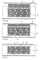
- Fig. 3A, 3B, 3C are partial views of the side wall of the basket according to an embodiment of the invention as developed in a hypothetical development plane.
- Fig. 4 is a cross-sectional view of the side wall of a basket according to an embodiment of the invention.
- Fig. 5 is an enlarged cross-sectional view of a part of the side wall, in which the height of the rounded projections and domes with through holes has been represented on an enlarged scale.
- a front-loading washing machine with a biased-axis tank is schematically shown in Fig. 1 .
- the washing machine which is generally designated with 1, comprises a cabinet 2, a tank 3 being housed therein, which consists of a generally cylindrical body, either made of plastic or stainless steel, with either biased or horizontal longitudinal axis X (as shown in Fig. 1 ).
- the tank 3 is coupled to the cabinet 2 by means of known means, which comprise shock absorbers and suspension springs, which are not shown in order to avoid burdening the drawing.
- the tank 3 is provided with a front aperture 5, having a generally round shape, which can be closed by means of a porthole being frontally hinged to the cabinet 2 and not shown, as known per se.
- a basket 6 is housed rotatably about the axis X, for the laundry to be accommodated therein to be washed and/or dried.
- the basket 6 comprises a side wall 7, a rear or bottom wall 8 and a front wall 9.
- the walls 7, 8 and 9 define an inner space 10 intended to accommodate the laundry to be washed and/or dried.
- the front wall 9 of the basket 6 is a stainless steel or plastic ring, with an aperture 11 having a generally round shape, which is placed such as to match the aperture 5 of the tank 3 to provide access to the inner space 10 to load/unload the laundry.
- the rear or bottom wall 8 of the basket 6 is preferably a substantially plane, centrally drawn, steel disk, being concave towards the outside of the basket.
- a support hub 4 for the basket In the middle of the rear wall 8 of the basket 6, there is mounted a support hub 4 for the basket, the basket being operatively connected therethrough to motor means (not shown), which control the rotation of the same about the longitudinal axis X.
- the side wall 7 of the basket is preferably obtained from a generally flat steel sheet, which is folded such as to form an approximatively rotational surface about a longitudinal central axis, being coincident with the longitudinal axis X of the tank 3 when in use.
- the coupling of the bottom 8 and front 9 walls to the side wall 7 is preferably provided by folding two end tracts of the sheet being the side wall 7, such as to give a C-shaped profile to the steel plate at both ends thereof.
- the bottom 8 and front 9 walls are shaped such as to define, at the outer edges thereof, profiles matching the C-shaped profile that is formed at both end tracts of the side wall 7.
- the basket 6 further comprises one or more, preferably three, dragging blades 12 that are arranged on the side wall 7 at 120° angular pitch and projecting towards the inside 10 of the basket.
- the side wall 7 of the basket is provided with perforations that provide, in the side wall, a pattern of a number of small through holes 13 that are substantially equidistant from each other and suitable to allow the lye to flow from the tank to the basket, and vice versa.
- Each of these small holes 13 is advantageously formed at the central vertex a dome 14 thereof, which is preferably formed by indentation, projecting to the outside of the basket.
- the drilled side wall 7 Due to the regular pattern of dome-shaped indentations 14 having 2 to 8 mm diameter, preferably 3 to 5 mm, and radially projecting to the outside of the basket, the drilled side wall 7 has a high rigidity and the edges of the small holes 13 result to be moved away from the laundry, such as to avoid an abrasive contact between the through holes 13 and the laundry.
- the drilling is preferably only provided on a main cylindrical band 15 and a front band 16 having the shape of a truncated cone of the side wall 7, which are separated from each other by a circumferential bending line 17.
- those areas immediately surrounding the bending line 17 between the main band 17 and the front band 18 is preferably not provided with perforations 13 such that relative folds are more easily carried out along continuous lines.
- the side wall 7, and particularly the main cylindrical band 15 comprises a plurality of rounded projections 18, which protrude within the basket.
- These rounded projections 18 are not provided with small through holes and have a diameter that is much greater that that of the small through holes 13 and domes 14 thereof.
- the rounded projections are also dome-, or cap-shaped (convex as seen from the inside of the basket), which is preferably formed by means of indentation.
- These rounded projections 18 have an outer diameter ranging between 10 mm and 30 mm, preferably about 20 mm, and a height ranging between about 1 mm and 4 mm, preferably 2 mm, and exert a dragging and "soft" lifting effect on the laundry in contact with the side wall 7 of the basket 6.
- the ratio of the outer diameter of the rounded projections (18) to the outer diameter of the domes (14) ranges between 2:1 and 4:1.
- a particular arrangement of the rounded projections 18 unusually contributes to an improved washing effectiveness, particularly on delicate garments.
- This arrangement of the rounded projections 18 is shown in Fig. 3A, 3B and 3C and provides for a circumferential sequence of individual groups of rounded projections 18 (in which each group advantageously comprises three projections 18) which define, in turn, an arrow-tip pattern, i.e. a triangular arrangement with the triangle vertex being oriented in the circumferential direction of the side wall 7.
- four of said groups of rounded projections 18 are formed between two of the three dragging blades 12.
- Fig. 3A, 3B and 3C show parts of the side wall 7 of baskets having different depths (or, in other words, longitudinal extensions), wherein the main cylindrical band 15 preferably has the same longitudinal extension, whereas the longitudinal extension of the front band 16 having the shape of a truncated cone changes according to the total depth of the basket. In the case of Fig. 3C , this front band 16 is very shallow and not provided with drilling.
- the particular pattern of the through holes 13 of the side wall 7, and particularly the rounded projections 18 facing the inside of the basket allow carrying out a very strong washing also on delicate garments, without the risk of damage due to excessive friction between the laundry and the side wall of the basket.
Landscapes
- Engineering & Computer Science (AREA)
- Textile Engineering (AREA)
- Main Body Construction Of Washing Machines And Laundry Dryers (AREA)
Claims (9)
- Tambour de chargement (6) pour une machine à laver (1), un lave-linge - sèche-linge, un sèche-linge et similaire, comprenant :une paroi arrière (8) destinée à être fixée sur une structure de support (4) du tambour ;une paroi avant (9) opposée à la paroi arrière (8),une paroi latérale (7) s'étendant autour d'un axe longitudinal (X), qui est l'axe de rotation du tambour et est raccordée aux parois arrière (8) et avant (9) afin de définir un espace interne (10) du tambour,une ou plusieurs pales traînantes (12) qui sont agencées sur la paroi latérale (7) et font saillie vers l'intérieur du tambour,dans lequel la paroi latérale (7) comprend des perforations se composant d'une pluralité de petits trous de passage (13), qui sont agencées au sommet des dômes (14) respectifs faisant saillie vers l'extérieur du tambour (6), ainsi qu'une pluralité de saillies arrondies (18) sans trou de passage faisant saillie vers l'intérieur (10) du tambour (6), caractérisé en ce que lesdites saillies arrondies (18) sont formées comme des dômes sphériques et ont un diamètre externe qui est plus grand que celui des petits trous de passage (13) et de leurs dômes (14).
- Tambour de chargement (6) selon la revendication précédente, dans lequel le rapport du diamètre externe des saillies arrondies (18) sur le diamètre externe des dômes (14) est compris entre 2:1 et 4:1.
- Tambour de chargement (6) selon l'une quelconque des revendications précédentes, dans lequel le diamètre externe des saillies arrondies (18) est compris entre 10 mm et 30 mm, de préférence environ 20 mm, et dans lequel la hauteur radiale des saillies arrondies (18) est comprise entre 1 mm et 4 mm, de préférence environ 2 mm.
- Tambour de chargement (6) selon l'une quelconque des revendications précédentes, comprenant une séquence circonférentielle de groupes individuels de saillies arrondies (18) qui définissent un motif en forme de pointe de flèche.
- Tambour de chargement (6) selon l'une quelconque des revendications précédentes, dans lequel chaque groupe de saillies arrondies comprend trois saillies arrondies (18) qui sont agencées afin de former un triangle avec le sommet du triangle qui est orienté dans la direction circonférentielle de la paroi latérale 7.
- Tambour de chargement (6) selon l'une quelconque des revendications précédentes, comprenant trois pales traînantes (12) qui sont agencées selon un écartement angulaire de 120°, dans lequel quatre desdits groupes de saillies arrondies (18) sont formés entre deux pales traînantes (12) respectivement.
- Tambour (6) selon l'une quelconque des revendications précédentes, dans lequel les trous de passage (13) sont sensiblement à égale distance les uns des autres, et les dômes (14) ont un diamètre compris entre 2 et 8 mm, de préférence 3 mm et 5 mm.
- Tambour de chargement (6) selon l'une quelconque des revendications précédentes, dans lequel la paroi latérale (7) du tambour est divisée en deux bandes de forme cylindrique (15) et/ou de forme tronconique (16) ou plus, au moyen de lignes de pliage circonférentielles (17), lesdites lignes de pliage (17) et les surfaces immédiatement adjacentes n'étant pas prévues avec des perforations ni des saillies arrondies.
- Machine à laver (1), lave-linge - sèche-linge, sèche-linge ou similaire, comprenant un tambour (6) selon l'une quelconque des revendications précédentes.
Priority Applications (4)
| Application Number | Priority Date | Filing Date | Title |
|---|---|---|---|
| EP06425467A EP1876280B1 (fr) | 2006-07-06 | 2006-07-06 | Tambour pour lave-linge, sèche-linge et similaires |
| DE602006017056T DE602006017056D1 (de) | 2006-07-06 | 2006-07-06 | Trommel für eine Waschmaschine, einen Waschtrockner und dergleichen |
| US11/812,632 US7661203B2 (en) | 2006-07-06 | 2007-06-20 | Basket for washing machine, washer-dryer, and the like |
| RU2007125426/12A RU2433214C2 (ru) | 2006-07-06 | 2007-07-05 | Барабан для стиральной машины, стирально-сушильной машины и тому подобное |
Applications Claiming Priority (1)
| Application Number | Priority Date | Filing Date | Title |
|---|---|---|---|
| EP06425467A EP1876280B1 (fr) | 2006-07-06 | 2006-07-06 | Tambour pour lave-linge, sèche-linge et similaires |
Publications (2)
| Publication Number | Publication Date |
|---|---|
| EP1876280A1 EP1876280A1 (fr) | 2008-01-09 |
| EP1876280B1 true EP1876280B1 (fr) | 2010-09-22 |
Family
ID=38670547
Family Applications (1)
| Application Number | Title | Priority Date | Filing Date |
|---|---|---|---|
| EP06425467A Ceased EP1876280B1 (fr) | 2006-07-06 | 2006-07-06 | Tambour pour lave-linge, sèche-linge et similaires |
Country Status (4)
| Country | Link |
|---|---|
| US (1) | US7661203B2 (fr) |
| EP (1) | EP1876280B1 (fr) |
| DE (1) | DE602006017056D1 (fr) |
| RU (1) | RU2433214C2 (fr) |
Families Citing this family (13)
| Publication number | Priority date | Publication date | Assignee | Title |
|---|---|---|---|---|
| KR101093878B1 (ko) * | 2004-06-05 | 2011-12-13 | 엘지전자 주식회사 | 건조기의 드럼 장치 |
| DE102005013052A1 (de) * | 2005-03-18 | 2006-09-21 | BSH Bosch und Siemens Hausgeräte GmbH | Wäschetrockenmaschine |
| EP1876280B1 (fr) * | 2006-07-06 | 2010-09-22 | Candy S.p.A. | Tambour pour lave-linge, sèche-linge et similaires |
| EP2363523B1 (fr) * | 2010-02-12 | 2014-05-07 | Asko Appliances AB | Pale de tambour pour machine à laver |
| RU2516147C1 (ru) * | 2012-09-28 | 2014-05-20 | Федеральное государственное бюджетное образовательное учреждение высшего профессионального образования "Южно-Российский государственный университет экономики и сервиса" (ФГБОУ ВПО "ЮРГУЭС") | Стиральная машина барабанного типа |
| USD713106S1 (en) * | 2013-01-02 | 2014-09-09 | General Electric Company | Basket for an appliance |
| USD713107S1 (en) * | 2013-01-02 | 2014-09-09 | General Electric Company | Basket for an appliance |
| USD700411S1 (en) * | 2013-02-07 | 2014-02-25 | Lg Electronics Inc. | Drum for washing machine |
| USD761501S1 (en) | 2013-09-27 | 2016-07-12 | Whirlpool Corporation | Container for clothes washing machine |
| KR102295607B1 (ko) * | 2014-03-07 | 2021-08-30 | 삼성전자주식회사 | 세탁기 및 이에 구비되는 세탁조의 제조방법 |
| KR101592318B1 (ko) * | 2014-12-09 | 2016-02-05 | 엘지전자 주식회사 | 건조기 |
| EP3412823B1 (fr) * | 2017-06-08 | 2022-03-30 | LG Electronics Inc. | Tambour de machine à laver |
| US10787764B1 (en) | 2019-06-17 | 2020-09-29 | Nathan Edward Day | Clothing ejection net for a washer or dryer and method of ejecting clothing from a washer or dryer |
Family Cites Families (133)
| Publication number | Priority date | Publication date | Assignee | Title |
|---|---|---|---|---|
| USRE25157E (en) * | 1962-04-10 | Best available copy | ||
| US2899816A (en) * | 1959-08-18 | jacobsen | ||
| US1410230A (en) * | 1919-03-18 | 1922-03-21 | Frederic H Vercoe | Drying machine |
| US1985485A (en) * | 1924-02-12 | 1934-12-25 | George C Graham | Apparatus for expressing liquids |
| US1588622A (en) * | 1925-01-06 | 1926-06-15 | Philip A Savoy | Washing machine |
| US1655514A (en) * | 1927-08-30 | 1928-01-10 | Nat Laundry Machine Co Inc | Drying tumbler |
| US1766310A (en) * | 1928-03-29 | 1930-06-24 | Fletcher Works | Hydro extractor |
| US2385223A (en) * | 1938-10-21 | 1945-09-18 | Stanley G Harwood | Clothes-drying machine |
| US2296262A (en) * | 1939-12-02 | 1942-09-22 | Westinghouse Electric & Mfg Co | Washing apparatus |
| US2262186A (en) * | 1940-03-08 | 1941-11-11 | Lindberg Bernhard | Laundry drying machine |
| US2358779A (en) * | 1942-05-07 | 1944-09-26 | American Tool & Machine Co | Centrifugal separator |
| US2592596A (en) * | 1945-08-24 | 1952-04-15 | Wilbert L Pengelly | Jet action washing machine |
| US2540955A (en) * | 1945-09-19 | 1951-02-06 | Hamilton Mfg Co | Laundry drier |
| US2574798A (en) * | 1946-01-07 | 1951-11-13 | Simplex | Washing and drying machine |
| US2608769A (en) * | 1946-07-19 | 1952-09-02 | Hamilton Mfg Co | Drier |
| US2574251A (en) * | 1947-07-03 | 1951-11-06 | Detrex Corp | Dry cleaning machine |
| US2547238A (en) * | 1947-08-12 | 1951-04-03 | Tremblay Gerard | Drying apparatus |
| US2648142A (en) * | 1947-08-16 | 1953-08-11 | Murray Corp | Clothes drier |
| US2645111A (en) * | 1947-11-05 | 1953-07-14 | Whirlpool Co | Wobble plate laundry machine |
| US2523305A (en) * | 1947-12-05 | 1950-09-26 | American Laundry Mach Co | Conveyer type washing machine |
| US2617203A (en) * | 1948-10-13 | 1952-11-11 | Orval D Murray | Drier |
| US2691883A (en) * | 1949-01-22 | 1954-10-19 | Easy Washing Machine Corp | Filtering |
| US2737729A (en) * | 1951-05-12 | 1956-03-13 | Murray Corp | Dryers |
| US2722751A (en) * | 1952-02-18 | 1955-11-08 | Maytag Co | Fluid conductor and lint collector for clothes drier |
| US2681513A (en) * | 1952-02-20 | 1954-06-22 | Paul L Fowler | Clothes drier with horizontal cylinder |
| US2695162A (en) * | 1952-11-10 | 1954-11-23 | Lovell Mfg Co | Drier |
| US2716820A (en) * | 1952-11-26 | 1955-09-06 | Temco Inc | Drying apparatus |
| US2798304A (en) * | 1954-04-20 | 1957-07-09 | Borg Warner | Mechanical control means for a clothes drier cylinder |
| US2798306A (en) * | 1954-04-20 | 1957-07-09 | Borg Warner | Laundry drying apparatus |
| US2930215A (en) * | 1955-05-02 | 1960-03-29 | Maytag Co | Tub assembly for washing machine |
| US2813414A (en) * | 1955-05-27 | 1957-11-19 | Westinghouse Electric Corp | Apparatus for washing and drying fabrics |
| US2802283A (en) * | 1955-08-01 | 1957-08-13 | George N Strike | Clothes pre-drier and conditioner |
| US2750782A (en) * | 1955-08-04 | 1956-06-19 | Gen Electric | Laundry apparatus |
| US2807890A (en) * | 1955-10-06 | 1957-10-01 | Gen Electric | Laundry machine having improved temperature sensing means |
| US2831333A (en) * | 1955-12-27 | 1958-04-22 | Maytag Co | Wobble plate laundry machine |
| US2976998A (en) * | 1956-12-03 | 1961-03-28 | Maytag Co | Damping system for a washing machine |
| US2974515A (en) * | 1957-02-04 | 1961-03-14 | Maytag Co | Wobble agitator |
| US2944415A (en) * | 1957-02-04 | 1960-07-12 | Maytag Co | Filter for washing machine |
| US2855698A (en) * | 1957-02-27 | 1958-10-14 | Easy Washing Machine Company L | Clothes drier drums |
| US2921384A (en) * | 1957-04-08 | 1960-01-19 | Maytag Co | Combination washer-drier |
| US2996809A (en) * | 1957-04-29 | 1961-08-22 | Borg Warner | Clothes dryer |
| US2991990A (en) * | 1957-07-10 | 1961-07-11 | Gen Motors Corp | Domestic appliance |
| US2974422A (en) * | 1958-05-27 | 1961-03-14 | Thermair Domestric Appliances | Centrifugal clothes driers |
| US3028740A (en) * | 1959-12-14 | 1962-04-10 | Gen Electric | Automatic clothes washing machine with multiple-compartment dispenser |
| US3084531A (en) * | 1960-03-17 | 1963-04-09 | L W Matheny | Self clothes-unloading device for laundry machine |
| US3198903A (en) * | 1962-07-12 | 1965-08-03 | Gen Electric | Control switch assembly, particularly for appliances such as clothes dryers |
| GB1046003A (fr) * | 1963-05-02 | 1966-10-19 | ||
| US3247689A (en) * | 1964-05-07 | 1966-04-26 | Westinghouse Electric Corp | Tub unit and suspension basic structure for agitator washer |
| US3320678A (en) * | 1965-01-27 | 1967-05-23 | Gen Electric | Easy clean lint filter |
| US3333346A (en) * | 1965-03-30 | 1967-08-01 | Gen Motors Corp | Domestic clothes dryer |
| US3357109A (en) * | 1965-08-17 | 1967-12-12 | Walter B Harvey | Portable dryer |
| US3352130A (en) * | 1966-01-07 | 1967-11-14 | Maytag Co | Filter for laundry machine |
| US3429056A (en) * | 1967-11-30 | 1969-02-25 | Gen Electric | Clothes dryer with selective clutch for drum rotation |
| US3555701A (en) * | 1969-05-15 | 1971-01-19 | Philco Ford Corp | Laundry apparatus |
| US3584394A (en) * | 1969-10-31 | 1971-06-15 | Gen Motors Corp | Triangular vane for a split drum dryer |
| US3616545A (en) * | 1969-11-28 | 1971-11-02 | Gen Electric | Clothes dryer with means to vary centrifugal forces on the clothes |
| US3624919A (en) * | 1970-03-13 | 1971-12-07 | Mc Graw Edison Co | Clothes drying blower with lint stripping device |
| FI55581C (fi) * | 1970-07-18 | 1979-08-10 | Arendt Hans F Maschbau | En foer torkning av tvaett eller dylikt avsedd trumtorkningsanordning |
| US3721015A (en) * | 1971-09-23 | 1973-03-20 | Gen Electric | Bearing assembly |
| US3718982A (en) * | 1971-10-27 | 1973-03-06 | Gen Motors Corp | Excess lint indicator for a clothes dryer |
| US3824705A (en) * | 1972-10-16 | 1974-07-23 | N Ives | Apparatus for drying grain |
| DE2363935C3 (de) * | 1973-12-20 | 1983-03-17 | Bosch-Siemens Hausgeräte GmbH, 7000 Stuttgart | Mantel für eine mantelbeschickbare Wäschetrommel einer Waschmaschine |
| US3969070A (en) * | 1975-02-12 | 1976-07-13 | Mcgraw-Edison Company | Clothes dryer with heat reclaimer |
| US4328600A (en) * | 1979-05-15 | 1982-05-11 | General Electric Company | Washing machine |
| US4507080A (en) * | 1983-07-22 | 1985-03-26 | Challenge Cook Bros., Inc. | Laundry dryer |
| US4502303A (en) * | 1983-10-31 | 1985-03-05 | White Consolidated Industries, Inc. | Washing machine tub construction |
| US4519223A (en) * | 1983-10-31 | 1985-05-28 | White Consolidated Industries, Inc. | Washing machine tub construction |
| CA1253334A (fr) * | 1985-10-11 | 1989-05-02 | Robert M. St. Louis | Support pliant sur sechoir de linge |
| IT211313Z2 (it) * | 1987-02-27 | 1989-03-06 | Meliconi Srl | Apparecchiatura per il lavaggio e l'asciugatura centrifuga di ortaggi verdure e simili |
| US4817298A (en) * | 1987-12-14 | 1989-04-04 | General Electric Company | Fabric dryer with improved blower assembly |
| US4817297A (en) * | 1987-12-14 | 1989-04-04 | General Electric Company | Fabric dryer support structure |
| US4835991A (en) * | 1987-12-24 | 1989-06-06 | Whirlpool Corporation | Automatic water level control system for an automatic washer |
| US4977479A (en) * | 1988-08-04 | 1990-12-11 | Rick Caroll | Static electricity eliminator in clothes dryers |
| SU1601250A2 (ru) * | 1988-12-26 | 1990-10-23 | Предприятие П/Я М-5612 | Стиральна машина |
| US5388298A (en) * | 1990-11-30 | 1995-02-14 | The Procter & Gamble Company | Device for the machine washing of clothes and the method of utilizing said device |
| US5143104A (en) * | 1990-12-07 | 1992-09-01 | Allergan, Inc. | Vented apparatus for storing and cleaning an element |
| US5044178A (en) * | 1991-01-28 | 1991-09-03 | Speed Queen Company | Rinse aid dispenser |
| US5220734A (en) * | 1991-03-12 | 1993-06-22 | L&W Designs | Apparatus comprising straps with end attachments for removably fastening objects to be dried within dryer drum |
| US5249441A (en) * | 1992-01-02 | 1993-10-05 | Whirlpool Corporation | Slit valve for automatic washer |
| US5191668A (en) * | 1992-01-02 | 1993-03-09 | Whirlpool Corporation | Spin method of rinsing fabric in a horizontal axis washer |
| US5271251A (en) * | 1992-01-02 | 1993-12-21 | Whirlpool Corporation | Vertical axis washer |
| US5219370A (en) * | 1992-01-02 | 1993-06-15 | Whirlpool Corporation | Tumbling method of washing fabric in a horizontal axis washer |
| US5233718A (en) * | 1992-01-02 | 1993-08-10 | Whirlpool Corporation | Tumble method of rinsing fabric in a horizontal axis washer |
| CA2062016C (fr) * | 1992-02-27 | 1999-07-27 | Robert Maurice St. Louis | Deflecteur a crans pour secheuse de linge |
| US5167898A (en) * | 1992-03-05 | 1992-12-01 | Triangle Tool Corporation | Injection mold assembly and method for manufacturing a plastic tub with holes |
| US5345637A (en) * | 1993-04-27 | 1994-09-13 | Whirlpool Corporation | High performance washing system for a horizontal axis washer |
| US5421103A (en) * | 1993-11-24 | 1995-06-06 | Maytag Corporation | Apparatus and method for drying fabrics |
| CA2142685A1 (fr) * | 1994-02-22 | 1995-08-23 | Dale E. Mueller | Methode de lavage dans une machine a axe vertical |
| CA2142687A1 (fr) * | 1994-02-22 | 1995-08-23 | Dale E. Mueller | Methode de rincage dans une machine a laver a axe vertical |
| US5460018A (en) * | 1994-02-22 | 1995-10-24 | Whirlpool Corporation | Vertical axis washer |
| DE4445669A1 (de) * | 1994-12-21 | 1996-06-27 | Aeg Hausgeraete Gmbh | Waschtrommel für eine Waschmaschine |
| US5463821A (en) * | 1995-01-03 | 1995-11-07 | Whirlpool Corporation | Method and apparatus for operating a microwave dryer |
| US5706588A (en) * | 1996-08-13 | 1998-01-13 | General Electric Company | Device and method for separating lint particles in a clothes dryer |
| US5833654A (en) * | 1997-01-17 | 1998-11-10 | C. R. Bard, Inc. | Longitudinally aligned dual reservoir access port |
| US6032821A (en) * | 1998-06-03 | 2000-03-07 | United States Filter Corporation | Center opening treatment tank |
| US6115863A (en) * | 1999-03-08 | 2000-09-12 | Whirlpool Corporation | Drive system for a vertical axis washer |
| US6324771B1 (en) * | 2000-02-08 | 2001-12-04 | Alliance Laundry Systems Llc | Drying tumbler with temperature limiting air flow bypass |
| DE10006975B4 (de) * | 2000-02-16 | 2004-08-12 | BSH Bosch und Siemens Hausgeräte GmbH | Wäschetrommel für eine Waschmaschine |
| US6845290B1 (en) * | 2000-05-02 | 2005-01-18 | General Electric Company | System and method for controlling a dryer appliance |
| US6430971B1 (en) * | 2000-05-16 | 2002-08-13 | Whirlpool Corporation | Spherical surface drive block for washing machine basket |
| US6412191B1 (en) * | 2001-04-12 | 2002-07-02 | Her Majesty The Queen In Right Of Canada, As Represented By The Minister Of Agriculture And Agri Food Canada | Method and apparatus for the removal of liquid from materials |
| JP3772821B2 (ja) * | 2001-10-23 | 2006-05-10 | エルジー電子株式会社 | 洗濯機 |
| KR20040105862A (ko) * | 2002-04-10 | 2004-12-16 | 피셔 앤 페이켈 어플라이언스 리미티드 | 세탁기 |
| US6968632B2 (en) * | 2002-04-10 | 2005-11-29 | Fisher & Paykel Appliances Limited | Laundry appliance |
| US6622618B1 (en) * | 2002-06-14 | 2003-09-23 | Bojour, Inc. | Salad spinner |
| US6751888B2 (en) * | 2002-09-26 | 2004-06-22 | General Electric Company | Clothes dryer adaptive heater control |
| US6757986B2 (en) * | 2002-11-18 | 2004-07-06 | Rhona Miller | Portable (mini) clothes & hair dryer |
| KR100459193B1 (ko) * | 2002-11-27 | 2004-12-03 | 엘지전자 주식회사 | 응축식 의류 건조기용 응축기의 냉각 유로 |
| US6995965B2 (en) * | 2002-12-12 | 2006-02-07 | General Electric Company | Clothes dryer over-voltage control apparatus and method |
| DE10260023B3 (de) * | 2002-12-19 | 2004-01-22 | Miele & Cie. Kg | Waschmaschinentrommel mit Schröpfrippen und Verfahren zur Herstellung des Mantels einer solchen Waschmaschinentrommel |
| KR100465729B1 (ko) * | 2003-01-15 | 2005-01-13 | 엘지전자 주식회사 | 건조기 |
| KR100587323B1 (ko) * | 2003-04-28 | 2006-06-08 | 엘지전자 주식회사 | 자동 건조기의 센서 장착 구조 |
| US6745495B1 (en) * | 2003-06-27 | 2004-06-08 | General Electric Company | Clothes dryer apparatus and method |
| US7627960B2 (en) * | 2003-06-30 | 2009-12-08 | General Electric Company | Clothes dryer drum projections |
| KR20050006328A (ko) * | 2003-07-08 | 2005-01-17 | 엘지전자 주식회사 | 드럼세탁기 |
| AU2004203379B2 (en) * | 2003-07-28 | 2006-10-12 | Lg Electronics Inc. | Washing machine |
| CN100334290C (zh) * | 2003-08-07 | 2007-08-29 | 三洋电机株式会社 | 烘干机 |
| WO2005032322A2 (fr) * | 2003-09-29 | 2005-04-14 | Self Propelled Research And Development Specialists, Llc | Seche-linge a pompe a chaleur |
| KR101012365B1 (ko) * | 2003-12-11 | 2011-02-09 | 엘지전자 주식회사 | 건조 드럼의 제조 방법 |
| EP1589144B1 (fr) * | 2004-04-21 | 2009-04-15 | Samsung Electronics Co., Ltd. | Sèche-linge |
| US6941679B1 (en) * | 2004-06-22 | 2005-09-13 | Alliance Laundry Systems Llc | Laundry machine with malfunction detection systems |
| KR20060097239A (ko) * | 2005-03-04 | 2006-09-14 | 삼성전자주식회사 | 의류 건조기와 의류 건조기의 이물질 제거방법 |
| CA2505565C (fr) * | 2005-04-28 | 2008-09-16 | Camco Inc. | Dispositif et methode de commande d'un seche-linge |
| CA2508607C (fr) * | 2005-05-30 | 2007-09-11 | Camco Inc. | Porte de secheuse |
| JP2007054351A (ja) * | 2005-08-25 | 2007-03-08 | Matsushita Electric Ind Co Ltd | 洗濯機 |
| EP1876281B1 (fr) * | 2006-07-06 | 2012-10-10 | Candy S.p.A. | Tambour pour machine à laver ou sèche-linge |
| EP1876280B1 (fr) * | 2006-07-06 | 2010-09-22 | Candy S.p.A. | Tambour pour lave-linge, sèche-linge et similaires |
| EP1876282A1 (fr) * | 2006-07-06 | 2008-01-09 | CANDY S.p.A. | Tambour pour machine à laver ou sèche-linge |
| CA2554497C (fr) * | 2006-07-28 | 2010-02-16 | Mabe Canada Inc. | Dispositif de fixation de roue de ventilateur pour secheuse a linge |
| US8087184B2 (en) * | 2006-07-28 | 2012-01-03 | General Electric Company | Clothes dryer with extendable rack |
| CA2610078A1 (fr) * | 2007-11-09 | 2009-05-09 | Mabe Canada Inc. | Charniere de porte de secheuse |
| CA2604668A1 (fr) * | 2007-09-28 | 2009-03-28 | Mabe Canada Inc. | Ensemble de support de tambour de secheuse de linge |
| CA2604671A1 (fr) * | 2007-09-28 | 2009-03-28 | Mabe Canada Inc. | Support de joint de roulement de secheuse de linge |
-
2006
- 2006-07-06 EP EP06425467A patent/EP1876280B1/fr not_active Ceased
- 2006-07-06 DE DE602006017056T patent/DE602006017056D1/de active Active
-
2007
- 2007-06-20 US US11/812,632 patent/US7661203B2/en not_active Expired - Fee Related
- 2007-07-05 RU RU2007125426/12A patent/RU2433214C2/ru not_active IP Right Cessation
Also Published As
| Publication number | Publication date |
|---|---|
| US20080005925A1 (en) | 2008-01-10 |
| US7661203B2 (en) | 2010-02-16 |
| EP1876280A1 (fr) | 2008-01-09 |
| RU2433214C2 (ru) | 2011-11-10 |
| DE602006017056D1 (de) | 2010-11-04 |
| RU2007125426A (ru) | 2009-01-10 |
Similar Documents
| Publication | Publication Date | Title |
|---|---|---|
| US7661203B2 (en) | Basket for washing machine, washer-dryer, and the like | |
| US7752872B2 (en) | Basket for washing machine, washer-dryer, dryer and the like | |
| KR100808204B1 (ko) | 드럼세탁기 | |
| EP1502982B1 (fr) | Machine à laver | |
| JP2957144B2 (ja) | 洗濯機用ボールバランサ | |
| RU2402651C2 (ru) | Бытовой водопотребляющий прибор с рельефным бельевым барабаном | |
| EP2719808B1 (fr) | Machine à laver | |
| RU2471024C2 (ru) | Устройство пульсатора, используемое со стиральной машиной, и стиральная машина, содержащая его | |
| EP2053152B1 (fr) | Lave-linge ou sèche-linge doté d'un tambour avec éléments de relèvement amovibles | |
| JP7018624B2 (ja) | 洗濯機 | |
| EP1619285B2 (fr) | Tambour pour machine à laver, sèche-linge, ou équivalent | |
| EP1876282A1 (fr) | Tambour pour machine à laver ou sèche-linge | |
| EP3715522B1 (fr) | Tambour de lavage d'une machine à laver le linge et machine à laver le linge équipée d'un tel tambour | |
| JP6484812B2 (ja) | ドラム式洗濯機 | |
| KR100644823B1 (ko) | 세탁기의 세탁조 | |
| KR20040081142A (ko) | 전방투입식 세탁드럼을 가진 드럼세탁기 | |
| US7428832B2 (en) | Drum washing machine | |
| JP7149461B2 (ja) | 洗濯機 | |
| JP2019024526A (ja) | 洗濯機 | |
| EP4640937A1 (fr) | Tambour pour machine à laver le linge, sèche-linge, lave-linge ou appareils similaires | |
| KR200378293Y1 (ko) | 드럼세탁기용 드럼 | |
| ES2390851T3 (es) | Una lavadora con eje horizontal con entrada en la cuba para alojar la juntura del tambor | |
| JP7225227B2 (ja) | 洗濯機 | |
| JP7018623B2 (ja) | 洗濯機 | |
| KR100215629B1 (ko) | 세탁기의 펄세이터 |
Legal Events
| Date | Code | Title | Description |
|---|---|---|---|
| PUAI | Public reference made under article 153(3) epc to a published international application that has entered the european phase |
Free format text: ORIGINAL CODE: 0009012 |
|
| AK | Designated contracting states |
Kind code of ref document: A1 Designated state(s): AT BE BG CH CY CZ DE DK EE ES FI FR GB GR HU IE IS IT LI LT LU LV MC NL PL PT RO SE SI SK TR |
|
| AX | Request for extension of the european patent |
Extension state: AL BA HR MK YU |
|
| 17P | Request for examination filed |
Effective date: 20080205 |
|
| 17Q | First examination report despatched |
Effective date: 20080414 |
|
| AKX | Designation fees paid |
Designated state(s): DE GB IT |
|
| GRAP | Despatch of communication of intention to grant a patent |
Free format text: ORIGINAL CODE: EPIDOSNIGR1 |
|
| GRAS | Grant fee paid |
Free format text: ORIGINAL CODE: EPIDOSNIGR3 |
|
| GRAA | (expected) grant |
Free format text: ORIGINAL CODE: 0009210 |
|
| AK | Designated contracting states |
Kind code of ref document: B1 Designated state(s): DE GB IT |
|
| REG | Reference to a national code |
Ref country code: GB Ref legal event code: FG4D |
|
| REF | Corresponds to: |
Ref document number: 602006017056 Country of ref document: DE Date of ref document: 20101104 Kind code of ref document: P |
|
| PLBE | No opposition filed within time limit |
Free format text: ORIGINAL CODE: 0009261 |
|
| STAA | Information on the status of an ep patent application or granted ep patent |
Free format text: STATUS: NO OPPOSITION FILED WITHIN TIME LIMIT |
|
| 26N | No opposition filed |
Effective date: 20110623 |
|
| REG | Reference to a national code |
Ref country code: DE Ref legal event code: R097 Ref document number: 602006017056 Country of ref document: DE Effective date: 20110623 |
|
| PGFP | Annual fee paid to national office [announced via postgrant information from national office to epo] |
Ref country code: IT Payment date: 20170706 Year of fee payment: 12 Ref country code: GB Payment date: 20170719 Year of fee payment: 12 |
|
| PGFP | Annual fee paid to national office [announced via postgrant information from national office to epo] |
Ref country code: DE Payment date: 20170929 Year of fee payment: 12 |
|
| REG | Reference to a national code |
Ref country code: DE Ref legal event code: R119 Ref document number: 602006017056 Country of ref document: DE |
|
| GBPC | Gb: european patent ceased through non-payment of renewal fee |
Effective date: 20180706 |
|
| PG25 | Lapsed in a contracting state [announced via postgrant information from national office to epo] |
Ref country code: GB Free format text: LAPSE BECAUSE OF NON-PAYMENT OF DUE FEES Effective date: 20180706 Ref country code: DE Free format text: LAPSE BECAUSE OF NON-PAYMENT OF DUE FEES Effective date: 20190201 |
|
| PG25 | Lapsed in a contracting state [announced via postgrant information from national office to epo] |
Ref country code: IT Free format text: LAPSE BECAUSE OF NON-PAYMENT OF DUE FEES Effective date: 20180706 |