EP1306538A2 - Dispositif et procédé de commande d'un moteur à combustion interne - Google Patents
Dispositif et procédé de commande d'un moteur à combustion interne Download PDFInfo
- Publication number
- EP1306538A2 EP1306538A2 EP02023688A EP02023688A EP1306538A2 EP 1306538 A2 EP1306538 A2 EP 1306538A2 EP 02023688 A EP02023688 A EP 02023688A EP 02023688 A EP02023688 A EP 02023688A EP 1306538 A2 EP1306538 A2 EP 1306538A2
- Authority
- EP
- European Patent Office
- Prior art keywords
- injection
- fuel injection
- rate
- fuel
- egr
- Prior art date
- Legal status (The legal status is an assumption and is not a legal conclusion. Google has not performed a legal analysis and makes no representation as to the accuracy of the status listed.)
- Withdrawn
Links
- 238000002485 combustion reaction Methods 0.000 title claims abstract description 44
- 238000000034 method Methods 0.000 title claims 2
- 238000002347 injection Methods 0.000 claims abstract description 198
- 239000007924 injection Substances 0.000 claims abstract description 198
- 239000000446 fuel Substances 0.000 claims abstract description 64
- 230000020169 heat generation Effects 0.000 claims abstract description 17
- 238000000746 purification Methods 0.000 claims abstract description 9
- QVGXLLKOCUKJST-UHFFFAOYSA-N atomic oxygen Chemical compound [O] QVGXLLKOCUKJST-UHFFFAOYSA-N 0.000 claims description 32
- 239000001301 oxygen Substances 0.000 claims description 32
- 229910052760 oxygen Inorganic materials 0.000 claims description 32
- 239000007789 gas Substances 0.000 claims description 29
- 230000009467 reduction Effects 0.000 claims description 20
- 239000000203 mixture Substances 0.000 claims description 4
- 230000001172 regenerating effect Effects 0.000 claims 1
- 230000000630 rising effect Effects 0.000 claims 1
- 239000003054 catalyst Substances 0.000 abstract description 16
- 230000004913 activation Effects 0.000 abstract description 5
- 230000008929 regeneration Effects 0.000 abstract description 4
- 238000011069 regeneration method Methods 0.000 abstract description 4
- 230000000087 stabilizing effect Effects 0.000 abstract description 2
- 238000012937 correction Methods 0.000 description 56
- 238000006722 reduction reaction Methods 0.000 description 17
- XLYOFNOQVPJJNP-UHFFFAOYSA-N water Substances O XLYOFNOQVPJJNP-UHFFFAOYSA-N 0.000 description 15
- 230000006835 compression Effects 0.000 description 12
- 238000007906 compression Methods 0.000 description 12
- 238000010586 diagram Methods 0.000 description 12
- 230000001590 oxidative effect Effects 0.000 description 7
- 230000007423 decrease Effects 0.000 description 6
- 238000010521 absorption reaction Methods 0.000 description 5
- 238000001514 detection method Methods 0.000 description 4
- 230000008859 change Effects 0.000 description 3
- 230000001133 acceleration Effects 0.000 description 2
- 238000006243 chemical reaction Methods 0.000 description 1
- 239000000498 cooling water Substances 0.000 description 1
- 230000003111 delayed effect Effects 0.000 description 1
- 230000006866 deterioration Effects 0.000 description 1
- 230000000694 effects Effects 0.000 description 1
- 230000008030 elimination Effects 0.000 description 1
- 238000003379 elimination reaction Methods 0.000 description 1
- 238000002474 experimental method Methods 0.000 description 1
- 230000004048 modification Effects 0.000 description 1
- 238000012986 modification Methods 0.000 description 1
- 238000011144 upstream manufacturing Methods 0.000 description 1
Images




Classifications
-
- F—MECHANICAL ENGINEERING; LIGHTING; HEATING; WEAPONS; BLASTING
- F02—COMBUSTION ENGINES; HOT-GAS OR COMBUSTION-PRODUCT ENGINE PLANTS
- F02D—CONTROLLING COMBUSTION ENGINES
- F02D35/00—Controlling engines, dependent on conditions exterior or interior to engines, not otherwise provided for
- F02D35/02—Controlling engines, dependent on conditions exterior or interior to engines, not otherwise provided for on interior conditions
- F02D35/028—Controlling engines, dependent on conditions exterior or interior to engines, not otherwise provided for on interior conditions by determining the combustion timing or phasing
-
- F—MECHANICAL ENGINEERING; LIGHTING; HEATING; WEAPONS; BLASTING
- F02—COMBUSTION ENGINES; HOT-GAS OR COMBUSTION-PRODUCT ENGINE PLANTS
- F02D—CONTROLLING COMBUSTION ENGINES
- F02D41/00—Electrical control of supply of combustible mixture or its constituents
- F02D41/02—Circuit arrangements for generating control signals
- F02D41/021—Introducing corrections for particular conditions exterior to the engine
- F02D41/0235—Introducing corrections for particular conditions exterior to the engine in relation with the state of the exhaust gas treating apparatus
- F02D41/024—Introducing corrections for particular conditions exterior to the engine in relation with the state of the exhaust gas treating apparatus to increase temperature of the exhaust gas treating apparatus
-
- F—MECHANICAL ENGINEERING; LIGHTING; HEATING; WEAPONS; BLASTING
- F02—COMBUSTION ENGINES; HOT-GAS OR COMBUSTION-PRODUCT ENGINE PLANTS
- F02D—CONTROLLING COMBUSTION ENGINES
- F02D41/00—Electrical control of supply of combustible mixture or its constituents
- F02D41/30—Controlling fuel injection
- F02D41/38—Controlling fuel injection of the high pressure type
- F02D41/40—Controlling fuel injection of the high pressure type with means for controlling injection timing or duration
- F02D41/402—Multiple injections
- F02D41/403—Multiple injections with pilot injections
-
- F—MECHANICAL ENGINEERING; LIGHTING; HEATING; WEAPONS; BLASTING
- F02—COMBUSTION ENGINES; HOT-GAS OR COMBUSTION-PRODUCT ENGINE PLANTS
- F02D—CONTROLLING COMBUSTION ENGINES
- F02D41/00—Electrical control of supply of combustible mixture or its constituents
- F02D41/30—Controlling fuel injection
- F02D41/38—Controlling fuel injection of the high pressure type
- F02D2041/389—Controlling fuel injection of the high pressure type for injecting directly into the cylinder
-
- F—MECHANICAL ENGINEERING; LIGHTING; HEATING; WEAPONS; BLASTING
- F02—COMBUSTION ENGINES; HOT-GAS OR COMBUSTION-PRODUCT ENGINE PLANTS
- F02D—CONTROLLING COMBUSTION ENGINES
- F02D41/00—Electrical control of supply of combustible mixture or its constituents
- F02D41/0025—Controlling engines characterised by use of non-liquid fuels, pluralities of fuels, or non-fuel substances added to the combustible mixtures
- F02D41/0047—Controlling exhaust gas recirculation [EGR]
- F02D41/0065—Specific aspects of external EGR control
- F02D41/0072—Estimating, calculating or determining the EGR rate, amount or flow
-
- F—MECHANICAL ENGINEERING; LIGHTING; HEATING; WEAPONS; BLASTING
- F02—COMBUSTION ENGINES; HOT-GAS OR COMBUSTION-PRODUCT ENGINE PLANTS
- F02D—CONTROLLING COMBUSTION ENGINES
- F02D41/00—Electrical control of supply of combustible mixture or its constituents
- F02D41/02—Circuit arrangements for generating control signals
- F02D41/021—Introducing corrections for particular conditions exterior to the engine
- F02D41/0235—Introducing corrections for particular conditions exterior to the engine in relation with the state of the exhaust gas treating apparatus
- F02D41/027—Introducing corrections for particular conditions exterior to the engine in relation with the state of the exhaust gas treating apparatus to purge or regenerate the exhaust gas treating apparatus
- F02D41/0275—Introducing corrections for particular conditions exterior to the engine in relation with the state of the exhaust gas treating apparatus to purge or regenerate the exhaust gas treating apparatus the exhaust gas treating apparatus being a NOx trap or adsorbent
-
- F—MECHANICAL ENGINEERING; LIGHTING; HEATING; WEAPONS; BLASTING
- F02—COMBUSTION ENGINES; HOT-GAS OR COMBUSTION-PRODUCT ENGINE PLANTS
- F02D—CONTROLLING COMBUSTION ENGINES
- F02D41/00—Electrical control of supply of combustible mixture or its constituents
- F02D41/30—Controlling fuel injection
- F02D41/38—Controlling fuel injection of the high pressure type
- F02D41/40—Controlling fuel injection of the high pressure type with means for controlling injection timing or duration
- F02D41/402—Multiple injections
-
- F—MECHANICAL ENGINEERING; LIGHTING; HEATING; WEAPONS; BLASTING
- F02—COMBUSTION ENGINES; HOT-GAS OR COMBUSTION-PRODUCT ENGINE PLANTS
- F02M—SUPPLYING COMBUSTION ENGINES IN GENERAL WITH COMBUSTIBLE MIXTURES OR CONSTITUENTS THEREOF
- F02M26/00—Engine-pertinent apparatus for adding exhaust gases to combustion-air, main fuel or fuel-air mixture, e.g. by exhaust gas recirculation [EGR] systems
- F02M26/02—EGR systems specially adapted for supercharged engines
- F02M26/04—EGR systems specially adapted for supercharged engines with a single turbocharger
- F02M26/05—High pressure loops, i.e. wherein recirculated exhaust gas is taken out from the exhaust system upstream of the turbine and reintroduced into the intake system downstream of the compressor
-
- F—MECHANICAL ENGINEERING; LIGHTING; HEATING; WEAPONS; BLASTING
- F02—COMBUSTION ENGINES; HOT-GAS OR COMBUSTION-PRODUCT ENGINE PLANTS
- F02M—SUPPLYING COMBUSTION ENGINES IN GENERAL WITH COMBUSTIBLE MIXTURES OR CONSTITUENTS THEREOF
- F02M26/00—Engine-pertinent apparatus for adding exhaust gases to combustion-air, main fuel or fuel-air mixture, e.g. by exhaust gas recirculation [EGR] systems
- F02M26/13—Arrangement or layout of EGR passages, e.g. in relation to specific engine parts or for incorporation of accessories
- F02M26/14—Arrangement or layout of EGR passages, e.g. in relation to specific engine parts or for incorporation of accessories in relation to the exhaust system
- F02M26/15—Arrangement or layout of EGR passages, e.g. in relation to specific engine parts or for incorporation of accessories in relation to the exhaust system in relation to engine exhaust purifying apparatus
-
- Y—GENERAL TAGGING OF NEW TECHNOLOGICAL DEVELOPMENTS; GENERAL TAGGING OF CROSS-SECTIONAL TECHNOLOGIES SPANNING OVER SEVERAL SECTIONS OF THE IPC; TECHNICAL SUBJECTS COVERED BY FORMER USPC CROSS-REFERENCE ART COLLECTIONS [XRACs] AND DIGESTS
- Y02—TECHNOLOGIES OR APPLICATIONS FOR MITIGATION OR ADAPTATION AGAINST CLIMATE CHANGE
- Y02T—CLIMATE CHANGE MITIGATION TECHNOLOGIES RELATED TO TRANSPORTATION
- Y02T10/00—Road transport of goods or passengers
- Y02T10/10—Internal combustion engine [ICE] based vehicles
- Y02T10/12—Improving ICE efficiencies
-
- Y—GENERAL TAGGING OF NEW TECHNOLOGICAL DEVELOPMENTS; GENERAL TAGGING OF CROSS-SECTIONAL TECHNOLOGIES SPANNING OVER SEVERAL SECTIONS OF THE IPC; TECHNICAL SUBJECTS COVERED BY FORMER USPC CROSS-REFERENCE ART COLLECTIONS [XRACs] AND DIGESTS
- Y02—TECHNOLOGIES OR APPLICATIONS FOR MITIGATION OR ADAPTATION AGAINST CLIMATE CHANGE
- Y02T—CLIMATE CHANGE MITIGATION TECHNOLOGIES RELATED TO TRANSPORTATION
- Y02T10/00—Road transport of goods or passengers
- Y02T10/10—Internal combustion engine [ICE] based vehicles
- Y02T10/40—Engine management systems
Definitions
- the present invention relates to a technology for stabilizing combustion performance in an engine when an air excess rate of a mixture supplied thereto is controlled to be reduced for an early activation of an exhaust gas purification catalyst and so on.
- a Japanese Unexamined Patent publication No. 2000-145508 discloses that combustion deterioration (combustion fluctuations) due to variations in an air excess rate is restricted by controlling a fuel injection timing based upon an output of a combustion pressure (cylinder pressure) sensor.
- combustion pressure cylinder pressure
- the present invention properly prevents an occurrence of combustion fluctuations when reduction control of an air excess rate is performed.
- the present invention is provided with a fuel injection valve which directly injects fuel into a combustion chamber and a fuel injection state of which varies so that the fuel injection state is controlled corresponding to a demand for reduction of the air excess rate by a control unit to maintain a crank angle position where a heat generation rate in the combustion chamber is maximized constant.
- Fig. 1 is a system view according to an embodiment of the present invention.
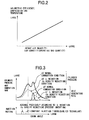
- Fig. 2 is a view showing a relationship between an operating gas quantity and a volumetric efficiency, and a temperature at a top dead center during a compression stroke (compression end temperature).
- Fig. 3 is a view showing a relationship between a pressure inside a cylinder and a heat generation rate at a normal combustion state and at a reduction state of an air excess rate.
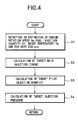
- Fig. 4 is a flowchart showing a control routine according to a first embodiment.
- Fig. 5 is a calculation block diagram at a target main injection timing according to the first embodiment.
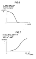
- Fig. 6 is a table map of a correction quantity, based upon the air excess rate, to main injection timing for use in calculation of the target main injection timing according to the first embodiment.
- Fig. 7 is a table map of a correction quantity, based upon an EGR rate, to the main injection timing for use in calculation of the target main injection timing according to the first embodiment.
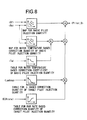
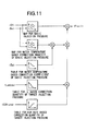
- Fig. 8 is a calculation block diagram of a target pilot injection quantity according to the first embodiment.
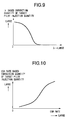
- Fig. 9 is a table map of a correction quantity, based upon the air excess rate, to a pilot injection quantity for use in calculation of the target pilot injection quantity according to the first embodiment.
- Fig. 10 is a table map of a correction quantity, based upon an EGR rate, to the pilot injection quantity for use in calculation of the target pilot injection quantity according to the first embodiment.
- Fig. 11 is a calculation block diagram of the target pilot injection quantity according to the first embodiment.
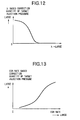
- Fig. 12 is a table map of a correction quantity, based upon the air excess rate, to an injection pressure for use in calculation of a target injection pressure according to the first embodiment.
- Fig. 13 is a table map of a correction quantity, based upon the EGR rate, to the injection pressure for use in calculation of the target injection pressure according to the first embodiment.
- Fig. 14 is a calculation block diagram of target main injection timing according to a second embodiment.
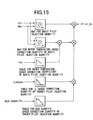
- Fig. 15 is a calculation block diagram of a target pilot injection quantity according to the second embodiment.
- Fig. 16 is a calculation block diagram of a target injection pressure according to the second embodiment.
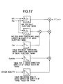
- Fig. 17 is a calculation block diagram of target main injection timing according to a third embodiment.
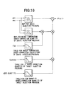
- Fig. 18 is a calculation block diagram of a target pilot injection quantity according to the third embodiment.
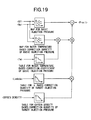
- Fig. 19 is a calculation block diagram of a target injection pressure according to the third embodiment.
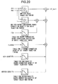
- Fig. 20 is a calculation block diagram of target main injection timing according to a fourth embodiment.
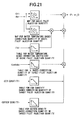
- Fig. 21 is a calculation block diagram of a target pilot injection quantity according to the fourth embodiment.
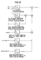
- Fig. 22 is a calculation block diagram of a target injection pressure according to the fourth embodiment.
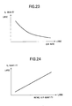
- Fig. 23 is a view showing a relationship between an EGR rate and an oxygen density.
- Fig. 1 shows a system of a diesel engine with a supercharger equipped with a control apparatus according to the present invention.
- an engine body 1 includes a common rail fuel injection system comprising a common rail 2, fuel injection valves 3 and a fuel pump (not shown), which supply a highly pressurized fuel to engine body 1.
- Fuel injection valves 3 directly inject fuel into a combustion chamber and enable a pilot injection prior to a main injection.
- a fuel injection pressure (hereinafter, injection pressure) of fuel injection valves 3 is controlled to vary by changing a fuel pressure set in common rail 2.
- a compressor 4a of a supercharger 4 is connected to an intake passage 5 and is driven for supplying pressurized air into engine body 1.
- a turbine 4b of supercharger 4 is connected to intake passage 5 and is driven by an exhaust gas from engine body 1 for driving compressor 4a.
- a variable volumetric type supercharger is used as supercharger 4 wherein at a low velocity region, a turbine efficiency improves by throttling a variable nozzle disposed in the side of turbine 4b and at a high velocity region, the variable nozzle opens to expand a turbine volume , thereby bring about a high supercharge effect in a wide operating region.
- An air flow meter 7 arranged upstream of compressor 4a of supercharger 4 and an intake throttle valve 8 are disposed in intake passage 5.
- an exhaust passage 6 In an exhaust passage 6 are disposed an EGR passage 9 branched from between engine body 1 and turbine 4b of supercharger 4 and connected to intake passage 5, an EGR valve 10 inserted in EGR passage 9, and NOx trap catalyst 11 and an oxidizing catalyst 12 with HC absorption functions disposed downstream of turbine 4b of supercharger 4.
- EGR valve 10 is an electrically controlled type valve using the step motor, which controls an exhaust gas quantity recirculated into the intake side corresponding to its opening angle, that is, an EGR quantity sucked into engine body 1.
- NOx trap catalyst 11 traps and reduces NOx in the exhaust gases.
- Oxidizing catalyst 12 with HC absorption function absorbs HC in the exhaust gases at a low temperature and oxidizes HC and CO.
- air flow meter 7 which detects an intake air quantity Qa
- a rotation velocity sensor 13 which detects an engine rotation speed Ne
- an acceleration opening angle sensor 14 which detects an acceleration opening angle
- a water temperature sensor 15 which detects a water temperature Tw
- a thermocouple 16,17 which detects a temperature of NOx trap catalyst 11 and oxidizing catalyst 12 with HC absorption function
- a rail pressure sensor 18 which detects a fuel pressure in common rail 2 (i.e., fuel injection pressure of fuel injection valve 3), and the like.
- a control unit 20 sets a fuel injection quantity Qf and a fuel injection timing IT based upon detection signals from various sensors and a detection signal from an auxiliary device 21 to control fuel injection valves 3 and also to control an opening angle of intake throttle valve 8 and EGR valve 10.
- the air excess rate is controlled to be reduced based upon the requirements (except change of the air excess rate due to change of engine operating conditions such as an engine rotation speed and an engine load), when an operating gas quantity (total quantity of the intake air quantity and the EGR quantity inside the cylinder) is reduced due to the reduction of the air excess rate, a temperature of the compression end (top dead center during compression stroke) is lowered as shown in Fig. 2.
- an injection state of the fuel from fuel injection valves 3 is variably controlled such that the crank angle position where the heat generation rate is maximized is kept constant.
- the engine rotation speed Ne the fuel injection quantity Qf, a cooling water temperature Tw, an actual air excess rate ⁇ , and an actual EGR rate are detected or estimated.
- the air excess rate ⁇ will be calculated by the following equation based upon the intake air quantity Qac detected by air flow meter 7, the fuel injection quantity Qf, and a theoretical air-fuel rate (14.6).
- ⁇ (Qac / Qf) / 14.6
- EGR rate Qec / Qac
- a target main injection timing of a main injection of fuel injection valves 3 is calculated based upon these values and at Step 3, a target pilot injection quantity in a pilot injection prior to the main injection is calculated, and at Step 4, a target injection pressure is calculated.
- basic injection timing is retrieved from a table map based upon a basic operating condition (fuel injection quantity Qf representing an engine load and engine rotation speed Ne).
- a final water temperature based correction quantity is calculated by multiplying a water temperature based correction quantity at the basic injection timing retrieved from the table map based upon the operating condition (Qf, Ne) by a water temperature based correction coefficient retrieved from a table map based upon the water temperature Tw.
- a ⁇ based correction quantity of the target injection timing is retrieved from a table map (Fig. 6) based upon the actual air excess rate ⁇ likewise, and an EGR rate based correction quantity of the target injection timing is retrieved from a table map (Fig. 7) based upon the actual EGR rate.
- the target main injection timing IT_ sol is calculated by adding a product of these correction quantities to the basic injection timing.
- the target main injection timing IT_sol is corrected in the advance direction further as much as the actual air excess rate ⁇ decreases or the actual EGR rate increases.
- a basic pilot injection quantity is retrieved from a table map based upon a basic operating condition (fuel injection quantity Qf representing an engine load and engine rotation speed Ne).
- a final water temperature based correction quantity is calculated by multiplying a water temperature based correction quantity at the basic injection quantity retrieved from the table map based upon the operating condition (Qf, Ne) likewise by a water temperature based correction coefficient retrieved from a table map based upon the water temperature Tw.
- a ⁇ based correction quantity of the target pilot injection quantity is retrieved from a table map (Fig. 9), and an EGR rate correction quantity of the target pilot injection quantity is retrieved from a table map (Fig. 10).
- a target pilot injection quantity is calculated by adding a total correction quantity multiplied by these correction quantities to the basic pilot injection quantity.
- the target pilot injection quantity is increasingly corrected by a large margin as much as the actual air excess rate ⁇ decreases or the actual EGR rate increases.
- a basic injection pressure is retrieved from a table map based upon a basic operating condition (fuel injection quantity Qf representing an engine load and engine rotation speed Ne).
- a final water temperature based correction quantity is calculated by multiplying a water temperature based correction quantity at the basic injection pressure retrieved from the table map by a water temperature based correction coefficient.
- a ⁇ based correction quantity of the target injection pressure is retrieved from a table map (Fig. 12), and an EGR rate correction quantity of the target injection pressure is retrieved from a table map (Fig. 13).
- a target injection pressure is calculated by adding a total correction quantity multiplied by these correction quantities to the basic injection pressure.
- the target injection pressure is increasingly corrected by a large margin as much as the actual air excess rate ⁇ decreases or the actual EGR rate increases.
- An on-off switching of the fuel injection valve and the common rail pressure are controlled for the target main injection timing, the target pilot injection quantity, and the target injection pressure as above.
- the ignition performance deteriorates due to reduction of the operating gas quantity and the crank angle position where the heat generation rate is maximized is getting away from the top dead center during compression stroke by lowering the combustion temperature due to reduction of the oxygen density
- the crank angle position gets close to the top dead center during compression stroke to maintain the position within a certain range by increasing the advance correction quantity of the main injection timing, the correction quantity of the target pilot injection quantity, and the correction pressure of the target injection pressure. Therefore, the combustion fluctuations can be restricted properly.
- the advance of the main injection timing and the increase pressure of the injection pressure guarantee the fuel injection quantity at a point when a compression temperature rises up, and the increase quantity of the pilot injection quantity brings about an increase quantity of a complimentary mixture quantity to improve the ignition performance and shorten an ignition delay period.
- the ignition delay period lengthens.
- the corrections are made based upon the air excess rate and the actual EGR rate, but it is not limited thereto, and in the second embodiment, the collections are based upon the air excess rate and the actual EGR quantity.
- the operating gas quantity gets larger in the case of the EGR valve control only. Therefore, the control is performed corresponding to an accurate operating gas quantity that allows for the air excess rate and also the actual EGR quantity.
- the target main injection timing is calculated as shown in Fig. 14.
- the basic injection timing, the water temperature based correction quantity of the basic injection timing, and the ⁇ based correction quantity of the target injection timing are calculated in the same way as the first embodiment and also the EGR quantity based correction quantity of the target injection timing (namely, the EGR quantity based correction quantity becomes smaller as the actual EGR quantity gets larger) is calculated based upon the actual EGR quantity (estimated value or detection value).
- a total correction quantity multiplied by these three correction quantities is added to the basic injection timing to calculate the target injection timing.
- the main injection timing in view of the ignition performance, is corrected to advance since the operating gas is reduced as the actual air excess rate is reduced.
- the main injection timing is corrected not to advance so much as compared with the small EGR quantity (namely, the advance correction quantity based upon the actual air excess rate is made small).
- a calculation of the pilot injection quantity and the injection pressure is made in the same way as the above and, as shown in Fig. 15 and Fig. 1 6, since reduction of the operating gas quantity becomes smaller as the actual EGR quantity is larger, the pilot injection quantity and the injection pressure are respectively corrected to be reduced.
- the crank angle position where the heat generation is maximized can be kept at the same position more accurately.
- a correction is made based upon the air excess rate and the oxygen density. This is because there are some cases where the combustion velocity differs when the oxygen density inside a cylinder differs, regardless of the same air excess rate.
- the target main injection timing is calculated as shown in Fig. 17.
- the basic injection timing, the water temperature based correction quantity of the basic injection timing, and the ⁇ based correction quantity of the target injection timing are calculated in the same way as the first embodiment and the second embodiment, and also the oxygen density based correction quantity of the target injection timing (namely, the oxygen density based correction quantity becomes larger as the oxygen density is lowered) is calculated based upon the oxygen density (estimated value or detection value).
- a total correction quantity multiplied by these three correction quantities is added to the basic injection timing to calculate the target injection timing.
- the main injection timing in view of the ignition performance, is corrected to advance since the operating gas is reduced more as the actual air excess rate is reduced and, in view of the combustion velocity, the main injection timing is corrected more to advance as the oxygen density is lowered.
- a calculation of the pilot injection quantity and the injection pressure is made in the same way as the above and, as shown in Fig. 18 and Fig. 19, since the ignition performance is lowered more as the oxygen density is lowered, the pilot injection quantity and the injection pressure are respectively corrected to be increased.
- the correction made based upon the oxygen density in addition to the air excess rate indicates that deviations in the heat generation rate due to decrease of the compression end temperature by the reduction of the oxygen density and due to slowing down the combustion velocity are corrected. Therefore, the crank angle position where the heat generation rate is maximized can be kept at the same position more accurately.
- a correction may be made based upon the air excess rate, the actual EGR quantity, and oxygen density.
- Fig. 20 - Fig. 22 show a fourth embodiment in regard to the correction based upon the air excess rate, the actual EGR quantity, and the oxygen density.
- the main injection timing in view of the ignition performance, is corrected to advance corresponding to the reduction of the air excess rate, and is corrected to retard corresponding to the reduction quantity of the operating gas being small when the actual EGR quantity at that moment is large (the advance correction quantity based upon the actual air excess rate is made small) and, in view of the combustion velocity, the main injection timing is corrected more for advance as the oxygen density is lowered.
- a calculation of the target pilot injection quantity and the target injection pressure is made in the same way as the above and, as shown in Fig. 21 and Fig. 22, as the oxygen density is lowered, the target pilot injection quantity and the target injection pressure are respectively corrected to be increased.
- the air excess rate and the actual EGR rate are used for the correction in place of the air excess rate, the actual EGR quantity, and the oxygen density. This is because the actual EGR rate has a relationship with the actual EGR quantity and the oxygen density.
- the EGR rate has an inversely proportional relationship with the oxygen density, a determination of the EGR rate directly leads to the oxygen density. Namely, when the EGR rate is found out, the EGR quantity and the oxygen density are found out. Then, using the relationship shown in the fourth embodiment, the main injection timing, the pilot injection quantity, and the injection pressure can be controlled.
- the correction quantity is equal to a total correction quantity of a retard correction quantity based upon the actual EGR quantity and an advance correction quantity based upon the oxygen density. Whether this total correction quantity is made in the retard direction or in the advance direction may be determined by an experiment. In the first embodiment, as shown in Fig. 5, it is made in the advance direction.
- the target pilot injection quantity and the target injection pressure are made in the same way as the above.
- the air excess rate and the EGR rate are estimated based upon the intake air quantity and the EGR quantity, but a correction quantity table map is respectively set to the intake air quantity and the EGR quantity, and thereby the air excess rate and the EGR rate can directly be corrected by the intake air quantity and the EGR quantity.
Landscapes
- Engineering & Computer Science (AREA)
- Chemical & Material Sciences (AREA)
- Combustion & Propulsion (AREA)
- Mechanical Engineering (AREA)
- General Engineering & Computer Science (AREA)
- Electrical Control Of Air Or Fuel Supplied To Internal-Combustion Engine (AREA)
- Output Control And Ontrol Of Special Type Engine (AREA)
- Exhaust Gas After Treatment (AREA)
- Combined Controls Of Internal Combustion Engines (AREA)
- Exhaust-Gas Circulating Devices (AREA)
Applications Claiming Priority (2)
| Application Number | Priority Date | Filing Date | Title |
|---|---|---|---|
| JP2001327236A JP3864754B2 (ja) | 2001-10-25 | 2001-10-25 | 内燃機関の制御装置 |
| JP2001327236 | 2001-10-25 |
Publications (2)
| Publication Number | Publication Date |
|---|---|
| EP1306538A2 true EP1306538A2 (fr) | 2003-05-02 |
| EP1306538A3 EP1306538A3 (fr) | 2004-10-20 |
Family
ID=19143497
Family Applications (1)
| Application Number | Title | Priority Date | Filing Date |
|---|---|---|---|
| EP02023688A Withdrawn EP1306538A3 (fr) | 2001-10-25 | 2002-10-22 | Dispositif et procédé de commande d'un moteur à combustion interne |
Country Status (3)
| Country | Link |
|---|---|
| US (1) | US6877479B2 (fr) |
| EP (1) | EP1306538A3 (fr) |
| JP (1) | JP3864754B2 (fr) |
Cited By (1)
| Publication number | Priority date | Publication date | Assignee | Title |
|---|---|---|---|---|
| EP1496236A3 (fr) * | 2003-07-08 | 2005-11-16 | Nissan Motor Company, Limited | Dispositif de commande de la combustion d'un moteur à combustion interne |
Families Citing this family (19)
| Publication number | Priority date | Publication date | Assignee | Title |
|---|---|---|---|---|
| JP4055670B2 (ja) | 2003-07-30 | 2008-03-05 | 日産自動車株式会社 | エンジンの排気浄化装置 |
| JP4466008B2 (ja) | 2003-07-31 | 2010-05-26 | 日産自動車株式会社 | エンジンの燃料噴射制御装置 |
| CA2442336C (fr) * | 2003-09-30 | 2006-09-19 | Westport Research Inc. | Methode et appareil d'alimentation de moteur a combustion interne a combustible gazeux a injection directe a rge elevee |
| CA2444163C (fr) * | 2003-10-01 | 2007-01-09 | Westport Research Inc. | Methode et appareil de controle de la qualite de la combustion dans un moteur a combustion interne a gaz |
| JP2006177241A (ja) * | 2004-12-22 | 2006-07-06 | Nissan Motor Co Ltd | 内燃機関の制御装置 |
| DE102005045294B4 (de) | 2005-09-22 | 2021-11-18 | Daimler Ag | Verfahren zum Betreiben einer Brennkraftmaschine |
| JP4538442B2 (ja) * | 2006-11-11 | 2010-09-08 | ボッシュ株式会社 | パイロット噴射制御方法及びその装置 |
| JP4899955B2 (ja) * | 2007-03-15 | 2012-03-21 | トヨタ自動車株式会社 | 内燃機関の制御装置 |
| DE602008000206D1 (de) * | 2007-06-27 | 2009-11-26 | Honda Motor Co Ltd | Steuersystem für einen Verbrennungsmotor |
| JP4760802B2 (ja) * | 2007-08-20 | 2011-08-31 | 株式会社デンソー | 燃料噴射制御装置及び燃料噴射制御システム |
| JP4743551B2 (ja) * | 2008-04-28 | 2011-08-10 | 株式会社デンソー | 内燃機関の制御装置 |
| JP4941429B2 (ja) * | 2008-08-07 | 2012-05-30 | トヨタ自動車株式会社 | 圧縮着火式内燃機関の燃料噴射パラメータ適合方法及び燃料噴射制御システム |
| JP5083228B2 (ja) * | 2009-01-19 | 2012-11-28 | トヨタ自動車株式会社 | 燃料噴射制御装置 |
| EP2392808A4 (fr) * | 2009-02-02 | 2015-10-21 | Toyota Motor Co Ltd | Dispositif de commande pour moteur à combustion interne |
| JP2010255528A (ja) * | 2009-04-24 | 2010-11-11 | Fuji Heavy Ind Ltd | エンジンの排気浄化装置 |
| US8433496B2 (en) * | 2010-05-18 | 2013-04-30 | GM Global Technology Operations LLC | Control system and method for improving cold startability of spark ignition direct injection (SIDI) engines |
| JP2013209943A (ja) * | 2012-03-30 | 2013-10-10 | Toyota Motor Corp | エンジンの燃料性状推定装置 |
| US9784201B2 (en) * | 2013-06-05 | 2017-10-10 | Toyota Jidosha Kabushiki Kaisha | Control device for internal combustion engine |
| JP6787140B2 (ja) * | 2017-01-12 | 2020-11-18 | トヨタ自動車株式会社 | 内燃機関の制御装置 |
Family Cites Families (9)
| Publication number | Priority date | Publication date | Assignee | Title |
|---|---|---|---|---|
| DE2840706C2 (de) * | 1977-09-21 | 1985-09-12 | Hitachi, Ltd., Tokio/Tokyo | Elektronische Steuereinrichtung zum Steuern des Betriebs einer Brennkraftmaschine |
| JPS5458115A (en) * | 1977-10-19 | 1979-05-10 | Hitachi Ltd | Engine controller |
| JPH01155053A (ja) | 1987-12-11 | 1989-06-16 | Mazda Motor Corp | ディーゼルエンジンの燃料制御装置 |
| JP3596013B2 (ja) | 1993-12-24 | 2004-12-02 | マツダ株式会社 | ディーゼルエンジンの排気浄化装置 |
| JPH11148410A (ja) | 1997-11-14 | 1999-06-02 | Isuzu Motors Ltd | エンジンにおけるパイロット燃料噴射量制御方法及びその装置 |
| JPH11294228A (ja) | 1998-04-10 | 1999-10-26 | Isuzu Motors Ltd | ディーゼルエンジンの燃料噴射制御装置 |
| JP3331991B2 (ja) | 1998-11-11 | 2002-10-07 | トヨタ自動車株式会社 | 内燃機関 |
| GB2344376A (en) | 1998-12-04 | 2000-06-07 | Lucas Ind Plc | I.c. engine fuel injection control method with determination of quantity of fuel delivered during pilot injection |
| US6659071B2 (en) * | 2000-05-08 | 2003-12-09 | Cummins Inc. | Internal combustion engine operable in PCCI mode with early control injection and method of operation |
-
2001
- 2001-10-25 JP JP2001327236A patent/JP3864754B2/ja not_active Expired - Fee Related
-
2002
- 2002-10-17 US US10/271,569 patent/US6877479B2/en not_active Expired - Fee Related
- 2002-10-22 EP EP02023688A patent/EP1306538A3/fr not_active Withdrawn
Non-Patent Citations (1)
| Title |
|---|
| None |
Cited By (1)
| Publication number | Priority date | Publication date | Assignee | Title |
|---|---|---|---|---|
| EP1496236A3 (fr) * | 2003-07-08 | 2005-11-16 | Nissan Motor Company, Limited | Dispositif de commande de la combustion d'un moteur à combustion interne |
Also Published As
| Publication number | Publication date |
|---|---|
| US6877479B2 (en) | 2005-04-12 |
| US20030079716A1 (en) | 2003-05-01 |
| JP3864754B2 (ja) | 2007-01-10 |
| EP1306538A3 (fr) | 2004-10-20 |
| JP2003129890A (ja) | 2003-05-08 |
Similar Documents
| Publication | Publication Date | Title |
|---|---|---|
| US6877479B2 (en) | Apparatus and a method for controlling an internal combustion engine | |
| US7159391B2 (en) | Method for restricting excessive temperature rise of filter in internal combustion engine | |
| US8958971B2 (en) | System and method to control an electronically-controlled turbocharger | |
| EP3187719B1 (fr) | Dispositif pour moteur à combustion interne | |
| US8903633B2 (en) | Control system for internal combustion engine | |
| EP2444641B1 (fr) | Dispositif de commande pour moteur à essence avec injection directe | |
| JPH04272463A (ja) | Ffv用エンジンのegr制御方法 | |
| JP2002089324A (ja) | 筒内噴射エンジンの燃料噴射制御装置 | |
| US6041757A (en) | Inter-cylinder-injection fuel controller for an internal combustion engine | |
| JP4833924B2 (ja) | 内燃機関の制御装置 | |
| JPH1193731A (ja) | 筒内噴射内燃機関の燃料噴射制御装置 | |
| EP1643110A1 (fr) | Moteur combustion interne | |
| JP4524966B2 (ja) | ディーゼル機関の制御システム | |
| EP1493483B1 (fr) | Dispositif de purification des gaz d'échappement d'un moteur à combustion interne | |
| JP2000227037A (ja) | 筒内噴射式内燃機関の制御装置 | |
| JPH10184418A (ja) | 希薄燃焼エンジンの排気浄化装置 | |
| JP2004346917A (ja) | 内燃機関制御装置 | |
| JP5925099B2 (ja) | 内燃機関の制御装置 | |
| JP7023129B2 (ja) | 内燃機関の制御装置 | |
| JP4247616B2 (ja) | ディーゼルエンジンの燃料噴射制御装置 | |
| JP3448862B2 (ja) | ディーゼル機関の制御装置 | |
| US20260139637A1 (en) | Control device for internal combustion engine | |
| JP4325517B2 (ja) | 内燃機関における燃料噴射制御方法 | |
| JP2987675B2 (ja) | 内燃機関の吸気制御装置 | |
| JP3189731B2 (ja) | 筒内噴射型火花点火式内燃エンジンの制御装置 |
Legal Events
| Date | Code | Title | Description |
|---|---|---|---|
| PUAI | Public reference made under article 153(3) epc to a published international application that has entered the european phase |
Free format text: ORIGINAL CODE: 0009012 |
|
| 17P | Request for examination filed |
Effective date: 20021022 |
|
| AK | Designated contracting states |
Designated state(s): AT BE BG CH CY CZ DE DK EE ES FI FR GB GR IE IT LI LU MC NL PT SE SK TR |
|
| AX | Request for extension of the european patent |
Extension state: AL LT LV MK RO SI |
|
| PUAL | Search report despatched |
Free format text: ORIGINAL CODE: 0009013 |
|
| AK | Designated contracting states |
Kind code of ref document: A3 Designated state(s): AT BE BG CH CY CZ DE DK EE ES FI FR GB GR IE IT LI LU MC NL PT SE SK TR |
|
| AX | Request for extension of the european patent |
Extension state: AL LT LV MK RO SI |
|
| AKX | Designation fees paid |
Designated state(s): DE FR GB |
|
| STAA | Information on the status of an ep patent application or granted ep patent |
Free format text: STATUS: THE APPLICATION IS DEEMED TO BE WITHDRAWN |
|
| 18D | Application deemed to be withdrawn |
Effective date: 20150501 |