EP1306709A2 - Vorrichtung zur Strahlführung eines Laserstrahls - Google Patents
Vorrichtung zur Strahlführung eines Laserstrahls Download PDFInfo
- Publication number
- EP1306709A2 EP1306709A2 EP02023280A EP02023280A EP1306709A2 EP 1306709 A2 EP1306709 A2 EP 1306709A2 EP 02023280 A EP02023280 A EP 02023280A EP 02023280 A EP02023280 A EP 02023280A EP 1306709 A2 EP1306709 A2 EP 1306709A2
- Authority
- EP
- European Patent Office
- Prior art keywords
- optical element
- seal
- holding
- clamping
- section
- Prior art date
- Legal status (The legal status is an assumption and is not a legal conclusion. Google has not performed a legal analysis and makes no representation as to the accuracy of the status listed.)
- Granted
Links
Images



Classifications
-
- G—PHYSICS
- G02—OPTICS
- G02B—OPTICAL ELEMENTS, SYSTEMS OR APPARATUS
- G02B7/00—Mountings, adjusting means, or light-tight connections, for optical elements
- G02B7/18—Mountings, adjusting means, or light-tight connections, for optical elements for prisms; for mirrors
- G02B7/182—Mountings, adjusting means, or light-tight connections, for optical elements for prisms; for mirrors for mirrors
-
- B—PERFORMING OPERATIONS; TRANSPORTING
- B23—MACHINE TOOLS; METAL-WORKING NOT OTHERWISE PROVIDED FOR
- B23K—SOLDERING OR UNSOLDERING; WELDING; CLADDING OR PLATING BY SOLDERING OR WELDING; CUTTING BY APPLYING HEAT LOCALLY, e.g. FLAME CUTTING; WORKING BY LASER BEAM
- B23K26/00—Working by laser beam, e.g. welding, cutting or boring
- B23K26/70—Auxiliary operations or equipment
- B23K26/702—Auxiliary equipment
Definitions
- the invention relates to a device for beam guidance of a laser beam with at least one optical element according to the preamble of claim 1.
- CO 2 lasers are used for flexible material processing, for example square-folded or coaxial CO 2 lasers.
- Discharge paths At the end of Discharge paths are provided optical elements for beam guidance, which are positioned on housing sections.
- the coaxial CO 2 lasers are unstable resonators with an annular discharge space, which, for example, have toroidal optical elements for beam guidance.
- optical elements used for beam guidance are dependent on their Function formed differently in their transmission and reflectance and adapted. There are optical elements used, the one Total reflection allow as well as optical elements that have a partial transmission allow with different degrees of permeability.
- a device for receiving the optical element which has a first annular body for supporting the optical element, which is arranged on the vacuum side of the laser path. Via an intermediate body, which surrounds the optical element in the radial direction, the optical element is positioned to the annular body. Subsequently, a holding body is placed on the intermediate body, which fixes the optical element axially to the first annular body. By screwing the intermediate body is first fixed to the ring body. Subsequently, the holding body is fixed by clamping screws, which penetrate the intermediate body to the ring body also. This arrangement is very time consuming in the assembly of the optical element and requires a high degree of precision in the manufacture of the component components.
- the laser radiation is coupled out via a recess in an annular mirror.
- the laser beam exits the vacuum chamber through a transmissive optical element that forms the end of the vacuum chamber. If the sealing of the optical element, for example by soldering, the soldered connection point is exposed during operation of the laser thermal cycling. As a result, the joint may leak over time.
- the invention is based on the object, a device for Beam guidance of a laser beam with at least one optical element to create a flat contact surface for complete installation of the optical Elementes and a simple and fast as well as tension-free installation of the optical element allows and has the required tightness.
- a tension-free arrangement of the optical element is given to the support section. Furthermore, it is characterized allows any geometry of an optical element to be used is. This may be a specific adaptation of the device be possible different beam profiles. This adaptation of the optical Elements to the beam profile has the advantage that a quick discharge the resulting in the optical element by the absorbed laser radiation Heat is possible. This can cause deformations of the optical element be kept low or be prevented.
- the optical element by the central force application completely abut the support portion and the flatness of the contact surface preserved, whereby a good heat dissipation is given.
- the central force application of the holding force with a clamping element is the further allows a simple mounting of the optical element for Housing section is given.
- the at least one optical element of the at least one retaining element and the clamping element can be simple and safely one after the other to the housing section to be mounted. Since that Clamping element has the effect of a central closure, the further a significant saving in assembly time can be achieved.
- the Arrangement of a fastening element on the housing portion for the Clamping element is further given a component reduction, whereby a Reduction of production costs is achieved.
- the Clamping element is designed as a screw ring. This is one in the assembly easy-to-handle clamping element given.
- the use of the screw ring as a clamping element allows one over the peripheral surface of the screw ring evenly distributed force on a holding element, whereby the optical element with a uniform contact pressure on the Pad portion of the housing portion rests.
- a clamping surface is provided, which has at least one section annular surface.
- This Design allows a between the clamping element and retaining ring reduced friction torque, allowing a transmission of the axial force without at least partial rotation of the holding element is made possible, whereby the optical element without changing its pre-fixed position for Support section is pressed.
- the holding element has a stop surface as tightening.
- a stop surface as tightening.
- the support section of the housing by turning or milling with diamond, Polycrystalline diamond (PCD), ceramics as well as grinding, precision turning or Lapping is made.
- PCD Polycrystalline diamond
- the Pad portion a higher contact area between the optical element and the support section, which leads to improved heat dissipation.
- a high degree of flatness for example, less than 10 microns, preferably less than 1 micron, achieved , whereby the power loss, resulting in a warming of the optical element is reduced, is reduced.
- a seal or a sealing damping element between the holding element and the optical Element is arranged so that by the different thermal expansion the optical element and the housing portion a tight arrangement between the optical element and a surrounding the optical element Housing section or a portion surrounding the optical element of the Holding element is given.
- a sufficient contact pressure of the optical element to Support section of the housing section remain maintained to a good Ensure heat dissipation.
- an advantageous embodiment of the invention provides that the optical element of diamond, zinc selenide, gallium arsenide, silicon or copper is formed.
- the material may be selected for the optical element.
- silicon is used in a quadratic folded CO 2 laser as a deflection mirror up to 4 kW and copper for a higher power range.
- Zinc selenide is preferably used as Auskoppelspiegel in a square folded CO 2 laser. With coaxial CO 2 lasers, zinc selenide can be used at low powers or diamond as the material for the optical element over all power ranges.
- an optical element deviating from a round Diameter in the outer contour is advantageously provided that the optical element by a frame in a position congruent to Outlet opening is fixed in the housing section. This allows the optical Element completely cover the outlet opening and the one on the Pad abutting portion of the optical element is preferably in all directions equal in amount. This can be a uniform Heat dissipation be given.
- the optical element has an adapted to the beam profile outer contour, which is preferably rectangular, banana-shaped or the like and in particular made of diamond.
- the geometry of the optical element is advantageous.
- the manufacturing costs of the optical element, in particular when using diamond can be reduced.
- the heat generated by the absorbed laser radiation can be dissipated directly via the contact surface into the housing section.
- a good tightness can be achieved.
- the heat generated by the absorbed laser radiation in the optical element can be dissipated very quickly in the cooled housing section.
- a low thermal expansion and a high mechanical strength is given.
- the optical element can essentially retain its original shape.
- diamond has a long service life even at higher powers.
- unstable resonators as is the case, for example, with CO 2 coaxial lasers, the laser beam is formed after leaving the vacuum chamber through mirrors and through a diaphragm. Here, the focus of the laser beam must lie in the aperture.
- the holding element has a voltage applied to the seal and circumferential Inclined surface, which seals at least in the direction of the, preferably a round outer contour having, optical element and / or fixed at least radially outwards. This allows a sealing Effect is achieved to the vacuum side of the housing section.
- the Seal is designed as an O-ring seal, which has an outer diameter equal to or greater than that of the optical element immediately surrounding housing portion or portion of the holding member is provided.
- This allows the optical element after insertion through the seal in held in a pre-assembled position. Furthermore, it will allows the retainer and the gasket to move during the Apply the holding force does not twist and the retaining element only one Movement executed in the axial direction on the optical element trimmed.
- the voltage applied directly to the housing portion seal is after the insertion of the retaining element a friction torque to the housing section and given at the oblique surface, which is greater than the friction torque between the Retaining element and the clamping element is. This allows the rotational movement of the clamping element converted into an axial movement of the holding element become.
- FIGS. 1 to 3 show a first embodiment of a device 11 according to the invention for the beam guidance of a laser beam.
- This device 11 is provided, for example, for the extraction of a laser beam in coaxial CO 2 lasers, which have a typical power range of, for example, 500 W to 2000 W.
- the device 11 according to FIG. 1 has a housing section 12.
- stepped through holes 14 are provided to fix by means of screws the housing portion 12, for example, to the resonator.
- the housing section 12 may be arranged on a closure lid of a resonator of a coaxial CO 2 laser.
- the housing section 12 is integrated in a closure cover of a coaxial CO 2 laser.
- a flange 17 For mounting the device 11 to a resonator is a flange 17 provided, which parallel to a support portion 18 for an optical Element 19 is formed with high precision.
- a circumferential collar 21 may be provided for additional guidance.
- This or the flange surface 17 surrounds a stepped bore 22, which on the support portion 18th adjacent a cross section preferably adapted to the beam profile having.
- the adjoining outlet opening 20 can be both round and be formed rectangular and banana-shaped. Every other geometry, which for the adaptation to the beam profile for beam guidance of a laser beam is required, can also be introduced.
- the optical element 19 lies with its narrow edge region on the Support section 18 on.
- a frame 23 surrounds the optical element 19 preferably completely and has a clearance fit to the optical element 19 on.
- the frame 23 has an outer peripheral surface 26, through which the frame 23 in a bore portion 27 of the housing portion 12th is guided. For complete contact with the support section 18 is in the Bore portion 27 adjacent to the support portion 18 Undercut 30 provided.
- the frame 23, which also has the function of a Intermediate body or adapter for adaptation to different body shapes has the optical elements 19, is disc-shaped and has a recess 28 which is larger than an opening 25 for the optical Element 19 is.
- the recess 28 is formed such that around the opening 25 of the frame 23 is a web-shaped bearing surface 33 is formed, on which after the introduction of the optical element 19, a further seal 29 for Plant comes. This seal 29 covers the gap between the optical Element 19 and the web-shaped bearing surface 33 of the frame 23 in order to Beam direction to allow a seal.
- a holding element 31 places the seal 29 to the optical element 19 and the web-shaped support surface 33 of the frame 23 fixed. It is preferable provided that an inner surface 32 of the holding element 31 with respect to a Peripheral surface 34 of the outlet opening 20 of the stepped bore 22 is flush or this one springs back. Likewise, the size of the seal 29th educated. This ensures that the through the peripheral surface 34th formed free area for beam guidance of the laser beam through the Beam outlet side positioned seal 29 and the retaining element 31 is not is reduced.
- the holding element 31 is fixed via a clamping element 36.
- the tensioning element 36 is advantageously designed as a clamping ring and engages over External thread 37 at a mounting portion 38 of the housing portion 12th on. As a result, a central force introduction to the holding element 31st allows.
- the external thread 37 may also be formed as a fine thread, so that a tightening torque of the clamping element 36 preferably via a Torque wrench can be set very sensitively.
- This clamping element 36 can also be introduced more clamping elements which fulfill the function that a finely dosed delivery of the Holding force on the holding member 31 is allowed to the optical element 19th to fix the support section 18 bracing and tilting free.
- the friction surfaces between the Retaining element 31 and the clamping element 36 in diameter as small as possible are, so that the resulting friction torque when tightening the clamping element 36th is small.
- a Positioning pin between the housing portion 12 and the frame 23rd is provided for the correct positioning of the frame 23 .
- the holding member 31 may preferably as tightening a Stop surface 41, which at an excessive torque on an end face 42 of the frame 23 comes to rest. This can be a Pinching the seal 29 and possibly damage the optical Elements 19 fail.
- the Stop surface 41 protruding on the end face 42 of the frame 23rd is provided.
- the housing portion 12 is preferably made of a material with a high Thermal conductivity formed. For example, aluminum alloys or the like used. These also have the advantage that both cost and precise machining is given.
- the Support section 18 is highly precise by turning or milling with diamond, Polycrystalline diamond (PCD), ceramics as well as grinding, precision turning or Lapping made. At the same time, this support portion 18 has a high degree on flatness to a full-surface contact of the edge portion of the optical Element 19 to allow. As a result, a good heat dissipation can be achieved become.
- a cooling channel 43 is close to the support section 18 provided, which preferably the outlet opening 20 near the support portion 18 completely surrounds.
- cooling channel 43 in the plan view of the housing portion 12 is shown.
- the optical one Element 19 surrounding cooling channel 43 has connecting pieces 44 for feeding and discharging a cooling liquid medium.
- the cooling channel 43 is for example, produced by drilling, which in the housing section 12 are introduced, that they open into each other.
- plug 46 are bore portions 47 used to make the cooling passage sections are required, medium sealed, so that a circumferential cooling channel 43 is formed.
- the optical element 19 is advantageously formed of diamond when using this device in a coaxial CO 2 laser.
- This material has the advantage of high thermal conductivity.
- diamond has a small thermal expansion coefficient, whereby the thermal expansions are low.
- the optical elements 19 formed of diamond have the advantage that the geometry is retained on absorption of the laser radiation and heating in the optical element. A change in the form of a thermal lens or the like is not given. As a result, a deflection-free exit of the laser beam can be given.
- FIG 3 is an exploded view of the device according to the invention shown in Figures 1 and 2.
- the housing section 12 By successively inserting the parts in the order shown in the direction of arrow 49 can be a fast and secure Assembly of an optical element 19 in the housing section 12 done. It can also be seen that a certain orientation of the parts and Positionally correct positioning results on the basis of the geometries on their own. It is also clear from this illustration that the housing section 12 also may be part of a closure element or lid of a resonator.
- the individual components such as the optical element 19, the frame 23, the Seals 24 and 29, the holding member 31 and the clamping element 36th can independently of the further coupling of the housing section 12th be used.
- the optical element 19 Due to the installation order, according to which first the frame 23 in the Bore portion 27 is inserted, the optical element 19 in its final position to the support portion 18 of the housing portion 12th be positioned.
- the subsequent insertion of the seal 29, the touchdown the holding element 31 and the tightening of the clamping element 36 allows a Fixing of the optical element 19 without twisting or tilting, so that a complete investment of the edge region of the optical element 19 on the Support section 18 is given without damaging these surfaces.
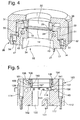
- FIG. 4 shows an alternative embodiment to FIG. Of the basic structure and the assembly sequence, as shown in Figure 3 is maintained.
- the frame 23 with a circumferential shoulder 51 an outer periphery 56 of the housing portion 12th embraces.
- the clamping element 36 engages around the shoulder 51 of the frame 23, by a screw on the mounting portion 38 of Housing section 12 attack.
- a stop surface 41 is provided, which in turn as tightening for the clamping element 36 is used.
- FIGS. 1 to 3 shows in contrast to the embodiment shown in Figures 1 to 3, that instead of installing the components in a housing section 12 also a fixation of the components by at least partially embracing the Housing section 12 is enabled. For the rest, the comments on the FIGS. 1 to 3.
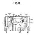
- FIGS. 5 to 8 show further alternative embodiments, for example, for a cross-sectionally round optical element 119, shown. Due to the round cross section of the frame 23 according to the Embodiments in Figures 1 and 4 omitted, causing the assembly the optical element 119 additionally facilitated.
- the embodiments according to FIGS. 5 to 8 can be used, for example, in the case of CO 2 lasers as output mirror, deflecting mirror, rearview mirror or partially transmitting mirror for checking the power of the laser beam.
- the materials Silicon, zinc selenide, gallium arsenide, diamond or copper with and without Coatings used are Silicon, zinc selenide, gallium arsenide, diamond or copper with and without Coatings used.
- the housing portion 112 in Figure 5 has stepped through holes 114th on, by means of screws the housing portion 112, for example, on a To fix resonator.
- a flange 117 is provided in the a centering pin 161 is used for positionally correct positioning.
- a seal 162 is provided to a first to the optical element 119 reaching portion of the housing portion 112nd Vacuum-tight to provide the resonator.
- the housing section 112 has a peripheral groove 163 on the outer circumference, in which a sleeve or sleeve can engage to connect with for example, one on an end face 164 of the housing portion 112 coupled beam telescope to form.
- the optical element 119 is attached to a support section 118 of the Housing portion 112 is provided.
- the support section 118 has a Flatness of less than 10 microns, for example 1 micron, on. Furthermore, it is by the finishing, as was carried out to Figure 1, a low Surface roughness given, thereby achieving increased heat dissipation becomes. Furthermore, due to the high degree of flatness an exact Alignment of the optical element 119 be given and the deformation be reduced.
- the outer diameter of the optical element 119 is opposite to the Diameter of a bore portion 127 designed such that a Clearance is provided. This clearance is especially easier Running seat trained. This is a tension-free recording in radial Direction even given a heating of the optical element 119.
- in the Transition region between the support portion 118 and the Bore portion 127 is a circumferential recess 130 and Undercut provided. This allows a complete and even plan Installation of the optical element 119 on the support section 118.
- the holding member 131 is inserted. This can radially through a guide surface 166 in the bore portion 127 be included. At this guide surface 166 closes in the direction of the optical element 119 an inwardly inclined inclined surface 167, which at a seal 129 attacks.
- This inclined surface 167 serves to seal the 129th at the same time against the housing portion 112 and the optical element 119 to press. About the angle of the inclined surface 167 can be the contact force or the bias on the housing portion 112th or distribute the optical element 119.
- the seal 129 is in formed in this embodiment as an O-ring seal. Of the Outer diameter of the seal 129 is the same, advantageously slightly larger than the diameter of the bore portion 127 formed. Thereby is guaranteed that from the beginning a friction between the Housing portion 112, the seal 129 and the holding member 131 is made.
- a Clamping element 136 is provided, which has a central holding force on the optical Element 119 on the holding element 131 applies.
- the clamping element 136 is as Screw ring formed and preferably has a fine thread. The fat of the screw ring is determined by a minimum number of threads to to apply the holding force.
- a clamping surface 169 is provided between the clamping element 136 and the Retaining element 131. This clamping surface 169 is as a narrow circumferential annular surface, preferably on the holding element 131, educated. Alternatively, this clamping surface 169 also on the clamping element 136 may be provided.
- the mean diameter of the clamping surface 169 is as possible small, so that between the holding member 131 and the Clamping element 136 resulting friction torque when tightening the clamping element 136 is smaller than the friction torque between the holding member 131 and the Seal 129 and the seal 129 and the housing portion 112th
- a stop surface 141 In the transition region between the bore portion 127 and the Attachment portion 138 is formed a stop surface 141, which as Tightening protection is used.
- the distance between a free, optical Element 119 facing end of the inclined surface 167 of the retaining element 131 and the stop surface 141 is dimensioned such that a resting of the free end the inclined surface 167 on the optical element 119 even at an elevated Tightening torque of the clamping element 136 does not occur.
- the inner diameter of the holding element 131 and the clamping element 136 are equal in diameter or larger than one formed on the support portion 118 adjacent portion in the housing portion 112th
- the optical element 119, the seal 129, the Retaining element 131 and the clamping element 136 is inserted.
- the Diameter at least slightly larger than the bore portion 127th formed seal 129 is that after insertion of the seal 129th the optical element 119 is pre-fixed to the support portion 18.
- the rotational movement of the clamping element 136 in a Axial movement are transmitted and the optical element 119th tension-free and tilt-free to the support portion 118 positioned become.
- the arrangement shown in Figure 5 for positioning the optical element 119 also has the advantage that a separate arrangement of Sealing functions and heat dissipation functions is given. Thereby can thermal changes of the optical element 119 due to absorbed laser radiation are kept low.
- Seal 129 as an O-ring can also be configured differently
- Spring element can be used, such as a coil spring, a Compression spring or the like to ensure a uniform and safe investment of optical element 119 to the support portion 118 to achieve.
- the cooling of the optical element 119 takes place in analogy to that in FIG. 2 shown cooling.
- the cooling channel 143 is as close to Pad portion 118 arranged.
- Such cooling is especially at larger laser powers and associated usually larger Mirror diameters advantageous.
- the Cooling optionally be provided.
- FIG. 6 shows an alternative embodiment to FIG. 5. in the following the deviations are explained in more detail. Regarding the identical embodiments will be based on the description of the previous figures directed.
- the holding member 231 has a ring portion 271 on, a radial peripheral surface 272 of the optical element 119 completely surrounds and abuts the bore portion 227 and is guided therein. Between the peripheral surface 272 of the optical element 219 and the Ring portion 271 of the holding member 231 is provided a fit, as between the second bore portion 127 and the optical element 119 in FIG Figure 5 is described.
- the retaining ring 231 has a through the end face of the Ring portion 271 formed stop surface 241. As tightening is provided that the distance between a free end of the inclined surface 267 and the abutment surface 241 at least slightly larger than the thickness of the optical element 219 and optionally applied thereto coating is.
- FIG. 7 shows a further alternative embodiment.
- This alternative embodiment corresponds to the basic structure according to the Embodiment in Figure 4 and is according to Figure 7 on a round optical Element 319 adapted.
- the holding element 331 has a guide surface 381, which abuts against an outer periphery 356 of the housing 312. Between the Outer periphery 356 of the housing 312 and the guide surface 381 is a Seal 382 provided.
- the optical element 319 is provided with a portion 383 guided.
- An Anzieh Klisch is provided in analogy to Figure 5 and by the outwardly directed annular collar 384 is formed.
- a Stage in a region surrounding the optical element 319 of the Holding element 331 may be provided, which on the support portion 318 for Plant comes.
- the tensioning element 336 engages a fastening portion 338 of the Housing section 312, which as external thread on the housing section is trained.
- the holding member 331 is of the clamping element 336 via the Ring collar 384 moved toward the optical element 319 to over the seal 329th to fix the optical element 319 to the support portion 318.
- the Housing portion 312 further includes a housing body 386 having the Housing circumference or the outer shape to a housing section completed, which corresponds to the housing portion 112 and 212 to independently the embodiment of holding element 331 and clamping element 336 a
- Figure 5 and 6 in the outer dimensions and function identical Embodiment to create.
- an additional seal 387 is provided, which prevents so-called fresh air from entering the beam path, when this embodiment is used as Auskoppelapt. simultaneously can by attaching this seal 387 a centering of the additional Housing body 386 be given.
- FIG. 8 shows a further alternative embodiment to FIGS. 5, 6 and 7 shown.
- the tensioning element 436 is in the attachment portion 438 provided and additionally has a sleeve 491, which the holding element 431 at least partially surrounds and leads.
- the tightening protection is to the effect provided by a stop surface 441 that the distance between the free end of the inclined surface 467 and the support portion 418 on the thickness of the optical element 419 and the height of the bore portion 427 is tuned.
Landscapes
- Physics & Mathematics (AREA)
- Engineering & Computer Science (AREA)
- Optics & Photonics (AREA)
- Plasma & Fusion (AREA)
- Mechanical Engineering (AREA)
- General Physics & Mathematics (AREA)
- Lasers (AREA)
- Laser Surgery Devices (AREA)
- Optical Couplings Of Light Guides (AREA)
Abstract
Description
- Figur 1
- eine schematische Darstellung im Querschnitt einer erfindungsgemäßen Vorrichtung,
- Figur 2
- eine schematische Draufsicht der Vorrichtung gemäß Figur 1,
- Figur 3
- eine Explosionsdarstellung der Vorrichtung gemäß Figur 1, in der die Einbaureihenfolge der Bauteile dargestellt ist,
- Figur 4
- eine schematische Darstellung im Querschnitt einer alternativen Vorrichtung zu Figur 1,
- Figur 5
- eine schematische Darstellung im Querschnitt einer weiteren alternativen Ausführungsform zu Figur 1,
- Figur 6
- eine schematische Darstellung im Querschnitt einer alternativen Vorrichtung zu Figur 5,
- Figur 7
- eine schematische Darstellung im Querschnitt einer weiteren alternativen Ausgestaltung zu Figur 5 und
- Figur 8
- eine schematische Darstellung im Querschnitt einer weiteren alternativen Ausgestaltung zu Figur 5.
Claims (15)
- Vorrichtung zur Strahlführung eines Laserstrahls mit zumindest einem optischen Element (19, 119, 219, 319, 419), welches mit einem Halteelement (31, 131, 231, 331, 431) zu einem Auflageabschnitt (18, 118, 218, 318, 418) positioniert ist und mit einem Spannelement (36, 136, 236, 336, 436), welches das optische Element (19, 119, 219, 319, 419) zum Auflageabschnitt (18, 118, 218, 318, 418) eines Gehäuseabschnitts (12, 112, 212, 312, 412) fixiert, dadurch gekennzeichnet, dass der den Auflageabschnitt (18, 118, 218, 318, 418) aufweisende Gehäuseabschnitt (12, 112, 212, 312, 412) einen Befestigungsabschnitt (38, 138, 238, 338, 438) aufweist, an welchem das Spannelement (36, 136, 236, 336, 436) zur zentralen Krafteinleitung einer Haltekraft angreift und das optische Element (19, 119, 219, 319, 419) unter Zwischenschaltung des zumindest einen Halteelements (31, 131, 231, 331, 431) zum Auflageabschnitt (18, 118, 218, 318, 418) positioniert.
- Vorrichtung nach Anspruch 1, dadurch gekennzeichnet, dass das Spannelement (36, 136, 236, 336, 436) als Schraubring ausgebildet ist.
- Vorrichtung nach Anspruch 1 oder 2, dadurch gekennzeichnet, dass zwischen dem Spannelement (36, 136, 236, 336, 436) und dem Halteelement (31, 131, 231, 331, 431) eine Spannfläche vorgesehen ist, die zumindest eine abschnittsweise Ringfläche aufweist.
- Vorrichtung nach einem der vorhergehenden Ansprüche, dadurch gekennzeichnet, dass das Halteelement (31, 131, 231, 331, 431) eine Anschlagfläche (41, 141, 241, 341, 441) als Anziehsicherung aufweist.
- Vorrichtung nach einem der vorhergehenden Ansprüche, dadurch gekennzeichnet, dass der Auflageabschnitt (18, 118, 218, 318, 418) durch Drehen oder Fräsen mit Diamant, Polykristallindiamant (PKD), Keramiken als auch Schleifen, Präzisionsdrehen oder Läppen bearbeitet ist.
- Vorrichtung nach einem der vorhergehenden Ansprüche, dadurch gekennzeichnet, dass der Auflageabschnitt (18, 118, 218, 318, 418) eine Ebenheit von weniger als 10 µm, vorzugsweise 1 µm, aufweist.
- Vorrichtung nach einem der vorhergehenden Ansprüche, dadurch gekennzeichnet, dass zwischen dem optischen Element (19, 119, 219, 319, 419) und dem Halteelement (31, 131, 231, 331, 431) eine Dichtung (29, 129, 229, 329, 429) vorgesehen ist.
- Vorrichtung nach einem der vorhergehenden Ansprüche, dadurch gekennzeichnet, dass das optische Element aus Diamant, Zinkselenid, Galliumarsenid, Silizium oder Kupfer ausgebildet ist.
- Vorrichtung nach einem der vorhergehenden Ansprüche, dadurch gekennzeichnet, dass zur Aufnahme eines optischen Elementes (19), welches von einer scheiben- oder zylinderartigen Form abweicht, ein Rahmen (23) vorgesehen ist, der das optische Element (19) zumindest teilweise umgibt und in einer Lage deckungsgleich zur Austrittsöffnung (20) im Gehäuseabschnitt (12) positioniert.
- Vorrichtung nach Anspruch 9, dadurch gekennzeichnet, dass das Halteelement (31) in eine Ausnehmung (28) des Rahmens (23) einsetzbar ist und das optische Element (19) und den Rahmen (23) zum Auflageabschnitt (18) fixiert.
- Vorrichtung nach Anspruch 9 oder 10, dadurch gekennzeichnet, dass zwischen dem Gehäuseabschnitt (12) und dem Rahmen (23) als auch zwischen dem optischen Element (19) und dem Halteelement (31) jeweils eine Dichtung (24, 29) vorgesehen ist.
- Vorrichtung nach einem der Ansprüche 9 bis 11, dadurch gekennzeichnet, dass das optische Element (19) eine an das Strahlprofil angepasste Außenkontur aufweist, die vorzugsweise rechteckförmig oder bananenförmig ausgebildet und insbesondere aus Diamant hergestellt ist.
- Vorrichtung nach einem der Ansprüche 1 oder 8, dadurch gekennzeichnet, dass das Halteelement (131, 231, 331, 431) eine an der Dichtung (129, 229, 329, 429) anliegende und umlaufende Schrägfläche (167, 267, 367, 467) aufweist, welche die Dichtung (129, 229, 329, 429) in axialer Richtung zum optischen Element (119, 219, 319, 419), das vorzugsweise eine runde Außenkontur aufweist, fixiert.
- Vorrichtung nach Anspruch 13, dadurch gekennzeichnet, dass zwischen dem Halteelement (131, 231, 331, 431) und dem vorzugsweise rund ausgebildeten optischen Element (119, 219, 319, 419) eine Dichtung (129, 229, 329, 429) vorgesehen ist, die als O-Ring-Dichtung ausgebildet ist.
- Vorrichtung nach einem der Ansprüche 13 oder 14, dadurch gekennzeichnet, dass die Dichtung (129, 429) im Außendurchmesser zumindest gleich oder größer als ein das optische Element (119, 419) umgebender Bohrungsabschnitt (127, 427) ausgebildet ist.
Applications Claiming Priority (2)
| Application Number | Priority Date | Filing Date | Title |
|---|---|---|---|
| DE10151587 | 2001-10-23 | ||
| DE10151587A DE10151587A1 (de) | 2001-10-23 | 2001-10-23 | Vorrichtung zur Strahlführung eines Laserstrahls |
Publications (3)
| Publication Number | Publication Date |
|---|---|
| EP1306709A2 true EP1306709A2 (de) | 2003-05-02 |
| EP1306709A3 EP1306709A3 (de) | 2004-06-23 |
| EP1306709B1 EP1306709B1 (de) | 2008-08-20 |
Family
ID=7703011
Family Applications (1)
| Application Number | Title | Priority Date | Filing Date |
|---|---|---|---|
| EP02023280A Expired - Lifetime EP1306709B1 (de) | 2001-10-23 | 2002-10-17 | Vorrichtung zur Strahlführung eines Laserstrahls |
Country Status (4)
| Country | Link |
|---|---|
| US (1) | US6700714B2 (de) |
| EP (1) | EP1306709B1 (de) |
| AT (1) | ATE405858T1 (de) |
| DE (2) | DE10151587A1 (de) |
Families Citing this family (14)
| Publication number | Priority date | Publication date | Assignee | Title |
|---|---|---|---|---|
| US7183548B1 (en) * | 2004-02-25 | 2007-02-27 | Metadigm Llc | Apparatus for modifying and measuring diamond and other workpiece surfaces with nanoscale precision |
| US7049544B2 (en) * | 2004-03-26 | 2006-05-23 | Ultratech, Inc. | Beamsplitter for high-power radiation |
| EP1643281A1 (de) * | 2004-10-02 | 2006-04-05 | Trumpf Werkzeugmaschinen GmbH + Co. KG | Optisches Element einer Laserbearbeitungsmaschine und Halterung des optischen Elements |
| ATE519560T1 (de) | 2004-10-20 | 2011-08-15 | Trumpf Werkzeugmaschinen Gmbh | Optisches element eines laserbearbeitungskopfs |
| DE102006046435B4 (de) * | 2006-09-22 | 2008-08-14 | Dreier Lasermesstechnik Gmbh | Messkugel-Reflektor |
| DE102006055738B4 (de) * | 2006-11-25 | 2010-10-07 | Trumpf Laser- Und Systemtechnik Gmbh | Vorrichtung zum Verändern des Strahldurchmessers eines durch ein optisches Element hindurchgehenden Laserstrahls mittels Temperaturänderung |
| JP5748205B2 (ja) | 2010-08-27 | 2015-07-15 | ギガフォトン株式会社 | ウィンドウユニット、ウィンドウ装置、レーザ装置及び極端紫外光生成装置 |
| JP5868670B2 (ja) | 2011-11-28 | 2016-02-24 | ギガフォトン株式会社 | ホルダ装置、チャンバ装置、および、極端紫外光生成装置 |
| JP5964383B2 (ja) | 2014-10-16 | 2016-08-03 | ファナック株式会社 | 弾性シール部材の取付治具 |
| GB201701173D0 (en) * | 2017-01-24 | 2017-03-08 | Element Six Tech Ltd | Synthetic diamond plates |
| DE102017209696A1 (de) * | 2017-06-08 | 2018-12-13 | Trumpf Laser Gmbh | Schutzglas mit Transponder und Einbauhilfe sowie zugehöriges Laserwerkzeug |
| DE102018115694A1 (de) * | 2018-06-28 | 2020-01-02 | Faurecia Emissions Control Technologies, Germany Gmbh | Fügevorrichtung |
| JP7291587B2 (ja) * | 2019-09-24 | 2023-06-15 | 三菱重工業株式会社 | レーザ加工ヘッドおよびレーザ加工装置 |
| CA3175132A1 (en) * | 2020-03-11 | 2021-09-16 | Arvind Sukumaran | External filter holder arrangement in operative microscopes for fluorescence guided surgery |
Family Cites Families (19)
| Publication number | Priority date | Publication date | Assignee | Title |
|---|---|---|---|---|
| DE2002361B2 (de) * | 1970-01-20 | 1975-05-07 | Balda-Werke Photographische Geraete Und Kunststoff Gmbh & Co Kg, 4980 Buende | Verfahren zur Herstellung eines Kamera-Suchergehäuses aus Kunststoff und Vorrichtung zur Durchführung des Verfahrens |
| JPS52156642A (en) * | 1976-06-21 | 1977-12-27 | Nec Corp | Laser mirror supporting device |
| DE3330626A1 (de) * | 1983-08-25 | 1987-06-25 | Wisotzki Juergen | Spiegel fuer die lasertechnik |
| JPS60189276A (ja) * | 1984-03-08 | 1985-09-26 | Sumitomo Electric Ind Ltd | レ−ザ共振器における反射鏡の冷却方法 |
| US4680771A (en) * | 1985-12-31 | 1987-07-14 | Amada Engineering Service Co., Inc. | Mirror adjustment device in laser oscillator |
| JPH0746736B2 (ja) * | 1986-10-09 | 1995-05-17 | 株式会社東芝 | 気体レーザ装置 |
| US4777639A (en) * | 1986-12-15 | 1988-10-11 | Prc Corporation | Laser optical element mounting arrangement and method |
| JPH0770767B2 (ja) * | 1987-03-19 | 1995-07-31 | 株式会社東芝 | レ−ザ用ミラ−保持機構 |
| DE4016579C2 (de) * | 1990-05-23 | 1994-12-15 | Fraunhofer Ges Forschung | Laser mit Schwingspiegel zur Leistungsmodulation |
| US5249082A (en) * | 1991-05-08 | 1993-09-28 | Eastman Kodak Company | Exact constraint arrangement for and methods of mounting an element such as a lens |
| DE9209561U1 (de) * | 1992-07-16 | 1992-11-05 | Weidmüller Interface GmbH & Co, 4930 Detmold | Fokussierungseinrichtung, insbesondere für einen Laser-Werkzeugkopf |
| US5392308A (en) * | 1993-01-07 | 1995-02-21 | Sdl, Inc. | Semiconductor laser with integral spatial mode filter |
| US5424872A (en) * | 1994-04-08 | 1995-06-13 | Recon/Optical, Inc. | Retrofit line of sight stabilization apparatus and method |
| JP2983148B2 (ja) * | 1994-12-02 | 1999-11-29 | 日本軽金属株式会社 | レーザ加工装置 |
| IT1277080B1 (it) * | 1995-12-14 | 1997-11-04 | Salvagnini Italia Spa | Testa di focalizzazione di un fascio laser dotata di una lente di focalizzazione per una macchina di lavorazione di pezzi metallici |
| GB2313472B (en) * | 1996-05-22 | 2000-10-18 | Avimo Ltd | Laser resonators |
| DE19628875C2 (de) * | 1996-07-17 | 2002-02-14 | Bayerische Motoren Werke Ag | Anordnung zum Herauslösen von PUR-Schaumkern aus Kraftfahrzeugsitzen |
| US5881088A (en) * | 1997-01-08 | 1999-03-09 | Trw Inc. | Face-cooled high-power laser optic cell |
| DE59802165D1 (de) * | 1997-09-05 | 2001-12-20 | Leica Microsystems | Mikroskop, insbesondere fluoreszenzmikroskop, insbesondere stereo-fluoreszenzmikroskop |
-
2001
- 2001-10-23 DE DE10151587A patent/DE10151587A1/de not_active Ceased
-
2002
- 2002-10-17 AT AT02023280T patent/ATE405858T1/de not_active IP Right Cessation
- 2002-10-17 DE DE50212665T patent/DE50212665D1/de not_active Expired - Lifetime
- 2002-10-17 EP EP02023280A patent/EP1306709B1/de not_active Expired - Lifetime
- 2002-10-23 US US10/280,583 patent/US6700714B2/en not_active Expired - Lifetime
Also Published As
| Publication number | Publication date |
|---|---|
| EP1306709A3 (de) | 2004-06-23 |
| DE10151587A1 (de) | 2003-05-22 |
| DE50212665D1 (de) | 2008-10-02 |
| ATE405858T1 (de) | 2008-09-15 |
| US20030123160A1 (en) | 2003-07-03 |
| US6700714B2 (en) | 2004-03-02 |
| EP1306709B1 (de) | 2008-08-20 |
Similar Documents
| Publication | Publication Date | Title |
|---|---|---|
| EP1306709A2 (de) | Vorrichtung zur Strahlführung eines Laserstrahls | |
| DE2532537C2 (de) | Einstellvorrichtung für koaxiale Maschinenteile | |
| DE3822445C2 (de) | ||
| DE3541744C2 (de) | ||
| DE10027662A1 (de) | Dichtmittel und Niederhalter für ein Brennstoffeinspritzventil | |
| DE8817078U1 (de) | Kupplungsvorrichtung zwischen einem Werkstück- oder Werkzeugträger und einer dafür vorgesehenen Handhabungseinrichtung | |
| DE102017209391B4 (de) | Selbstzentrierende Linsenanordnung für eine transmittive, refraktive Optik | |
| DE102021116607B3 (de) | Hydraulische Dehnspanneinrichtung | |
| DE102008035224B4 (de) | Laseroszillator mit einer Befestigungskonstruktion für ein optisches Element | |
| EP4377043A1 (de) | Halteanordnung für ein optisches element einer laserbearbeitungsanlage | |
| EP1915577B1 (de) | Befeuchter | |
| EP1706654B1 (de) | Gewindering | |
| DE10234104B3 (de) | Bremsscheibe mit Verbindungsring | |
| EP1235090B1 (de) | Vorrichtung zur Strahlführung eines Laserstrahls | |
| DE3913626A1 (de) | Spannvorrichtung fuer schaftwerkzeuge und zugehoeriges werkzeug | |
| DE102023121546A1 (de) | Düsenkühlelement und Laserbearbeitungsvorrichtung mit einem Düsenkühlelement | |
| EP0051327A1 (de) | Druckwellenmaschine zur Aufladung von Verbrennungsmotoren | |
| EP1515172B1 (de) | Spannungsarme Optikfassung | |
| EP1423644B1 (de) | Schneidbrenner | |
| EP0850715A1 (de) | Wendeschneidwerkzeug | |
| DE69126216T2 (de) | Rotierendes ringförminges Schneidewerkzeug | |
| DE10352820A1 (de) | Flanschbaugruppe eines optischen Systems | |
| EP1271023A2 (de) | Gleitringdichtungsanordnung | |
| DE4232326A1 (de) | Koppelanordnung für die Kopplung einer optischen Faser an ein optoelektronisches Modul | |
| DE9109300U1 (de) | Spannzangenfutter |
Legal Events
| Date | Code | Title | Description |
|---|---|---|---|
| PUAI | Public reference made under article 153(3) epc to a published international application that has entered the european phase |
Free format text: ORIGINAL CODE: 0009012 |
|
| AK | Designated contracting states |
Designated state(s): AT BE BG CH CY CZ DE DK EE ES FI FR GB GR IE IT LI LU MC NL PT SE SK TR |
|
| AX | Request for extension of the european patent |
Extension state: AL LT LV MK RO SI |
|
| PUAL | Search report despatched |
Free format text: ORIGINAL CODE: 0009013 |
|
| AK | Designated contracting states |
Kind code of ref document: A3 Designated state(s): AT BE BG CH CY CZ DE DK EE ES FI FR GB GR IE IT LI LU MC NL PT SE SK TR |
|
| AX | Request for extension of the european patent |
Extension state: AL LT LV MK RO SI |
|
| 17P | Request for examination filed |
Effective date: 20040916 |
|
| 17Q | First examination report despatched |
Effective date: 20041202 |
|
| AKX | Designation fees paid |
Designated state(s): CH DE FR GB IT LI |
|
| RBV | Designated contracting states (corrected) |
Designated state(s): AT BE BG CH CY CZ DE DK EE ES FI FR GB GR IE IT LI LU MC NL PT SE SK TR |
|
| GRAP | Despatch of communication of intention to grant a patent |
Free format text: ORIGINAL CODE: EPIDOSNIGR1 |
|
| GRAS | Grant fee paid |
Free format text: ORIGINAL CODE: EPIDOSNIGR3 |
|
| GRAA | (expected) grant |
Free format text: ORIGINAL CODE: 0009210 |
|
| RAP1 | Party data changed (applicant data changed or rights of an application transferred) |
Owner name: TRUMPF LASER- UND SYSTEMTECHNIK GMBH |
|
| AK | Designated contracting states |
Kind code of ref document: B1 Designated state(s): AT BE BG CH CY CZ DE DK EE ES FI FR GB GR IE IT LI LU MC NL PT SE SK TR |
|
| REG | Reference to a national code |
Ref country code: GB Ref legal event code: FG4D Free format text: NOT ENGLISH |
|
| REG | Reference to a national code |
Ref country code: CH Ref legal event code: EP |
|
| REG | Reference to a national code |
Ref country code: IE Ref legal event code: FG4D Free format text: LANGUAGE OF EP DOCUMENT: GERMAN |
|
| REF | Corresponds to: |
Ref document number: 50212665 Country of ref document: DE Date of ref document: 20081002 Kind code of ref document: P |
|
| REG | Reference to a national code |
Ref country code: CH Ref legal event code: NV Representative=s name: E. BLUM & CO. AG PATENT- UND MARKENANWAELTE VSP |
|
| PG25 | Lapsed in a contracting state [announced via postgrant information from national office to epo] |
Ref country code: NL Free format text: LAPSE BECAUSE OF FAILURE TO SUBMIT A TRANSLATION OF THE DESCRIPTION OR TO PAY THE FEE WITHIN THE PRESCRIBED TIME-LIMIT Effective date: 20080820 Ref country code: ES Free format text: LAPSE BECAUSE OF FAILURE TO SUBMIT A TRANSLATION OF THE DESCRIPTION OR TO PAY THE FEE WITHIN THE PRESCRIBED TIME-LIMIT Effective date: 20081201 |
|
| PG25 | Lapsed in a contracting state [announced via postgrant information from national office to epo] |
Ref country code: FI Free format text: LAPSE BECAUSE OF FAILURE TO SUBMIT A TRANSLATION OF THE DESCRIPTION OR TO PAY THE FEE WITHIN THE PRESCRIBED TIME-LIMIT Effective date: 20080820 |
|
| REG | Reference to a national code |
Ref country code: IE Ref legal event code: FD4D |
|
| BERE | Be: lapsed |
Owner name: TRUMPF LASER- UND SYSTEMTECHNIK G.M.B.H. Effective date: 20081031 |
|
| PG25 | Lapsed in a contracting state [announced via postgrant information from national office to epo] |
Ref country code: IE Free format text: LAPSE BECAUSE OF FAILURE TO SUBMIT A TRANSLATION OF THE DESCRIPTION OR TO PAY THE FEE WITHIN THE PRESCRIBED TIME-LIMIT Effective date: 20080820 Ref country code: DK Free format text: LAPSE BECAUSE OF FAILURE TO SUBMIT A TRANSLATION OF THE DESCRIPTION OR TO PAY THE FEE WITHIN THE PRESCRIBED TIME-LIMIT Effective date: 20080820 Ref country code: BG Free format text: LAPSE BECAUSE OF FAILURE TO SUBMIT A TRANSLATION OF THE DESCRIPTION OR TO PAY THE FEE WITHIN THE PRESCRIBED TIME-LIMIT Effective date: 20081120 |
|
| PG25 | Lapsed in a contracting state [announced via postgrant information from national office to epo] |
Ref country code: PT Free format text: LAPSE BECAUSE OF FAILURE TO SUBMIT A TRANSLATION OF THE DESCRIPTION OR TO PAY THE FEE WITHIN THE PRESCRIBED TIME-LIMIT Effective date: 20090120 Ref country code: CZ Free format text: LAPSE BECAUSE OF FAILURE TO SUBMIT A TRANSLATION OF THE DESCRIPTION OR TO PAY THE FEE WITHIN THE PRESCRIBED TIME-LIMIT Effective date: 20080820 Ref country code: MC Free format text: LAPSE BECAUSE OF NON-PAYMENT OF DUE FEES Effective date: 20081031 Ref country code: SK Free format text: LAPSE BECAUSE OF FAILURE TO SUBMIT A TRANSLATION OF THE DESCRIPTION OR TO PAY THE FEE WITHIN THE PRESCRIBED TIME-LIMIT Effective date: 20080820 |
|
| PLBE | No opposition filed within time limit |
Free format text: ORIGINAL CODE: 0009261 |
|
| STAA | Information on the status of an ep patent application or granted ep patent |
Free format text: STATUS: NO OPPOSITION FILED WITHIN TIME LIMIT |
|
| REG | Reference to a national code |
Ref country code: FR Ref legal event code: ST Effective date: 20090630 |
|
| 26N | No opposition filed |
Effective date: 20090525 |
|
| GBPC | Gb: european patent ceased through non-payment of renewal fee |
Effective date: 20081120 |
|
| PG25 | Lapsed in a contracting state [announced via postgrant information from national office to epo] |
Ref country code: EE Free format text: LAPSE BECAUSE OF FAILURE TO SUBMIT A TRANSLATION OF THE DESCRIPTION OR TO PAY THE FEE WITHIN THE PRESCRIBED TIME-LIMIT Effective date: 20080820 |
|
| PG25 | Lapsed in a contracting state [announced via postgrant information from national office to epo] |
Ref country code: IT Free format text: LAPSE BECAUSE OF FAILURE TO SUBMIT A TRANSLATION OF THE DESCRIPTION OR TO PAY THE FEE WITHIN THE PRESCRIBED TIME-LIMIT Effective date: 20080820 |
|
| PG25 | Lapsed in a contracting state [announced via postgrant information from national office to epo] |
Ref country code: BE Free format text: LAPSE BECAUSE OF NON-PAYMENT OF DUE FEES Effective date: 20081031 |
|
| PG25 | Lapsed in a contracting state [announced via postgrant information from national office to epo] |
Ref country code: FR Free format text: LAPSE BECAUSE OF NON-PAYMENT OF DUE FEES Effective date: 20081031 |
|
| PG25 | Lapsed in a contracting state [announced via postgrant information from national office to epo] |
Ref country code: GB Free format text: LAPSE BECAUSE OF NON-PAYMENT OF DUE FEES Effective date: 20081120 |
|
| PG25 | Lapsed in a contracting state [announced via postgrant information from national office to epo] |
Ref country code: AT Free format text: LAPSE BECAUSE OF NON-PAYMENT OF DUE FEES Effective date: 20081017 Ref country code: SE Free format text: LAPSE BECAUSE OF FAILURE TO SUBMIT A TRANSLATION OF THE DESCRIPTION OR TO PAY THE FEE WITHIN THE PRESCRIBED TIME-LIMIT Effective date: 20081120 |
|
| PG25 | Lapsed in a contracting state [announced via postgrant information from national office to epo] |
Ref country code: CY Free format text: LAPSE BECAUSE OF FAILURE TO SUBMIT A TRANSLATION OF THE DESCRIPTION OR TO PAY THE FEE WITHIN THE PRESCRIBED TIME-LIMIT Effective date: 20080820 Ref country code: LU Free format text: LAPSE BECAUSE OF NON-PAYMENT OF DUE FEES Effective date: 20081017 |
|
| PG25 | Lapsed in a contracting state [announced via postgrant information from national office to epo] |
Ref country code: TR Free format text: LAPSE BECAUSE OF FAILURE TO SUBMIT A TRANSLATION OF THE DESCRIPTION OR TO PAY THE FEE WITHIN THE PRESCRIBED TIME-LIMIT Effective date: 20080820 |
|
| PG25 | Lapsed in a contracting state [announced via postgrant information from national office to epo] |
Ref country code: GR Free format text: LAPSE BECAUSE OF FAILURE TO SUBMIT A TRANSLATION OF THE DESCRIPTION OR TO PAY THE FEE WITHIN THE PRESCRIBED TIME-LIMIT Effective date: 20081121 |
|
| PGFP | Annual fee paid to national office [announced via postgrant information from national office to epo] |
Ref country code: DE Payment date: 20161020 Year of fee payment: 15 Ref country code: CH Payment date: 20161025 Year of fee payment: 15 |
|
| REG | Reference to a national code |
Ref country code: DE Ref legal event code: R119 Ref document number: 50212665 Country of ref document: DE |
|
| REG | Reference to a national code |
Ref country code: CH Ref legal event code: PL |
|
| PG25 | Lapsed in a contracting state [announced via postgrant information from national office to epo] |
Ref country code: DE Free format text: LAPSE BECAUSE OF NON-PAYMENT OF DUE FEES Effective date: 20180501 Ref country code: LI Free format text: LAPSE BECAUSE OF NON-PAYMENT OF DUE FEES Effective date: 20171031 Ref country code: CH Free format text: LAPSE BECAUSE OF NON-PAYMENT OF DUE FEES Effective date: 20171031 |