EP1308089A2 - Tiertränke und Verfahren zur Umrüstung derselben - Google Patents
Tiertränke und Verfahren zur Umrüstung derselben Download PDFInfo
- Publication number
- EP1308089A2 EP1308089A2 EP02023938A EP02023938A EP1308089A2 EP 1308089 A2 EP1308089 A2 EP 1308089A2 EP 02023938 A EP02023938 A EP 02023938A EP 02023938 A EP02023938 A EP 02023938A EP 1308089 A2 EP1308089 A2 EP 1308089A2
- Authority
- EP
- European Patent Office
- Prior art keywords
- water
- valve
- drinking
- supply line
- actuating
- Prior art date
- Legal status (The legal status is an assumption and is not a legal conclusion. Google has not performed a legal analysis and makes no representation as to the accuracy of the status listed.)
- Granted
Links
Images



Classifications
-
- A—HUMAN NECESSITIES
- A01—AGRICULTURE; FORESTRY; ANIMAL HUSBANDRY; HUNTING; TRAPPING; FISHING
- A01K—ANIMAL HUSBANDRY; AVICULTURE; APICULTURE; PISCICULTURE; FISHING; REARING OR BREEDING ANIMALS, NOT OTHERWISE PROVIDED FOR; NEW BREEDS OF ANIMALS
- A01K7/00—Watering equipment for stock or game
- A01K7/02—Automatic devices
- A01K7/06—Automatic devices actuated by the animal
-
- A—HUMAN NECESSITIES
- A01—AGRICULTURE; FORESTRY; ANIMAL HUSBANDRY; HUNTING; TRAPPING; FISHING
- A01K—ANIMAL HUSBANDRY; AVICULTURE; APICULTURE; PISCICULTURE; FISHING; REARING OR BREEDING ANIMALS, NOT OTHERWISE PROVIDED FOR; NEW BREEDS OF ANIMALS
- A01K39/00—Feeding or drinking appliances for poultry or other birds
- A01K39/02—Drinking appliances
- A01K39/0213—Nipple drinkers
Definitions
- the invention relates to an animal cabinets according to the preamble of claim 1 and 10, respectively and a method for retrofitting the animal cabinets according to the preamble of the claim 15th
- the animal cabinets has an elongated Water supply line, to which preferably several watering valves with regular Distances are connected.
- Each watering valve is a water catcher assigned. In it collects from the drinking valve water discharged, and In particular, splash water that is not drunk directly.
- the animals can preferably by their beaks a respective watering valve for a short time immediately open and drink the water directly.
- the invention is based on the object, an animal feeders and a method for To create the same, which eliminates the problems of pollution and the Splash formation can be avoided more reliably and with which in particular turkeys, and also turkey chicks, preferably throughout the rearing and fattening selbttätig can cover their water needs sufficiently.
- a troughs for solving the above object has the features of Claim 1.
- the actuating means serves at the same time, the accessibility to operate the drinking valve for to improve small animals.
- the actuating means is the valve pin of the respective drinking valve assigned such that by a movement of the actuating means of the valve pin in a water release permitting position can be brought.
- the actuating means leaves make themselves larger than the usually only with a short operating end the valve of the drinking valve outstanding valve pin.
- the actuating means can form a kind of lever that not only for the animals, especially small turkey chicks is easier to reach; rather allows for easier movement of the valve pin. It then practically enough to open the potions valve already when the animals with preferably only touch the beak or head of the actuating means to the Valve pin in a the drinking valve opening, thus releasing the water outflow To give an opinion.
- the animal drinking in the invention is Actuating means designed to pivot.
- the actuating means is um a fixed pivot axis pivotally extending horizontally and thereby is arranged transversely to the longitudinal axis of an elongated water supply line.
- the so pivotable actuating means allows a particularly easy opening of the Potions valve too. Due to the horizontal arrangement of the pivot axis transversely to the longitudinal direction of the water supply line, the actuating means is only in one along the water supply line extending axis in opposite Swiveling directions. By longitudinal oscillation of the water supply line can due to the targeted arrangement of the pivot axis, the actuating means automatically, namely due to gravity, in a position opening the drinking valve reach. This makes it possible, with freshly housed, chicks, in particular Turkey chicks, all immobile attached to the water supply line water collecting trays to fill at the same time with a certain amount of water, the chicks tethered to the animal cabinets.
- the pivot axis about which the actuating means is pivotable is after a preferred embodiment of the invention an integral part of a holder, in particular a clamping bracket, with which the actuating means to the water supply line or the watering valve or a holder of the drinking valve at the water supply line, can be coupled.
- the preferably releasably trained Bracket allows the actuator to be used as a replacement when needed, but especially to remove when in the stable older, stronger animals which open and close the watering valves without the actuating means as well as the operation of the drinking valve to reduce aggression need. Such animals may optionally open the drinking valve further than it does is possible by the actuating means, so that by removing the actuating means the better the water needs of the animals become over time leaves.
- the actuating means is preferably designed as an actuating lever, the one having elongated tube.
- This pipe can be discharged from the drinking valve Liquid, especially water, targeted into the immobile water collection tray reach.
- the pipe directs the water from the watering valve into the lower one relatively for watering valve immovably arranged water collecting tray, so that reliable a splashing of water is avoided, thus reducing the associated disadvantage can not occur anymore.
- the tube of the Bottom of the drinking valve to near the bottom of the preferably vertical guided in a watering valve arranged water collecting tray. This can be done an upper end of the tube to the down from the housing of the drinking valve coupling the outstanding actuating end of the valve pin of the drinking valve.
- Cross-sectional shape or cross-sectional shape may be the cross-sectional area of the water receiving trough increase disproportionately with the water level. This allows the Wasseringmulde with, for example, doppelpfelndem water level far absorb more than twice the amount of water. This is especially true of turkeys, and in particular, turkey chicks, who with the operation of the animal bowls not yet are sufficiently familiar, the advantage of having their full water drip tray Can cover water demand, without the watering valve by, for example, the To open actuating means.
- the water receiving trough is formed to be near their bottom has an approximately circular cross section, concentric with the preferably also circular cross-section of the actuating means extends.
- This circular cross-section in the bottom area of the water intake trough goes larger The distance from the bottom area gradually over into a cross section of a another shape, preferably with an elliptical or oval cross-section.
- the water receiving trough receives a relatively large amount towards the upper edge elongated figure, the upper area of the water receiving trough a gives relatively large water absorption capacity.
- the elongated water receiving trough is longitudinal to the water supply line oriented, such that the longitudinal center axis of the water receiving trough runs parallel to the longitudinal center axis of the water supply line, wherein preferably the longitudinal central axis of the water receiving trough with a (imaginary) vertical plane covers, passing through the longitudinal central axes of the water supply line runs and connected to this Tränkeventile.
- the water drip tray is below the water supply pipe. whereby the water catcher also effective against pollution especially the water contained therein is protected.
- the elongated shape the water collecting tray also allows self-cleaning of the same by the Feather dress of the animals.
- a method for solving the above object has the measures of Claim 15. Accordingly, the animal cabinets can be converted by an exchange the water drip tray. Thus, with increasing age of the animals, if you are Increased water consumption, the water collecting trays with lower water absorption capacity against water receptacles with a larger water absorption capacity replaced. This replacement can be achieved by releasably attaching the Water catchment tray in particular the water supply line quickly and simply be made. All other components of the animal cabinets, in particular the watering valves, do not need to be changed.
- the Water outlet quantity changed per unit time from the watering valve.
- the animal bowls shown here is as a so-called string drinkers for the floor keeping of Poultry trained.
- the animal feeders makes it possible for all types of poultry, in particular also young animals (chicks), to cover the water demand automatically.
- the animal feeders according to the invention is also suitable for turkeys and turkey chicks.
- the animal feeders shown in Figs. 1 to 4 has an elongated, tubular Water supply line 20 with a plurality of spaced drinking stations 19, all of which are equally trained.
- the water supply line 20 is not on shown carrier cables in a stable hoizontalgeograph with appropriate (small) distance from the ground.
- Tränkeventile 21 of screwed in below.
- Tränkeventile 21 a partially having an external thread housing for screwing into corresponding Threaded holes of the water supply line 20.
- the preferably mutually identical drinking valves 21 have a valve pin, which projects out of the housing 22 with an actuating end 23 at the bottom.
- the respective drinking valve 21 can be opened, whereby from the water supply line 20 the watering valves 21 supplied water down from the drinking valves 21 can flow out in metered quantities.
- the watering valve 21 closes automatically, causing the further water outflow is interrupted from the feeding valve 21.
- Each watering valve 21 is associated with a water collecting tray 24.
- the water collecting trays 24 solvable, but stationary and immovable, with the Water supply line 21 connected.
- the operating lever 25 is pivotable relative to the respective water collecting tray 24 on or in the Area of the water supply line 20 stored and in an upper area the actuating end 23 of the valve pin of each drinking valve 21 is coupled.
- the Operating lever 50 is connected to the actuating end 23 of the valve pin.
- the Actuating levers 25 and 50 are from the respective watering valve 21 into the Water catch tray 24 out and thereby extend practically the operating end 23 of each valve pin into the area of the water collecting tray 24.
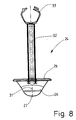
- the water collecting tray 24 shown in detail in FIGS. 6 to 8 is according to the invention especially for the water supply of small, young animals, in particular the raising of turkey chicks, trained.
- the independent water supply of Turkey chicks with animal feeders of the kind described here have so far been considered very proved problematic because the turkey chicks are less able to learn and shy.
- the special design of the water collecting tray 24, and in particular the to Receiving a water supply serving water receiving trough 26 of the same, has also in the automatic water supply of particular turkey chicks, as proven workable.
- the water receiving trough 26 of the water collecting tray 24 shown here has over an elongated, ship-like figure. This changes the cross-sectional shape the water receiving trough 26 from the lowest point 27 in the bottom area to the upper edge 28, preferably continuously.
- One from the lowest point 27 outgoing lower part of the water receiving trough 26 is a circular Cross section provided. This circular cross section goes to the upper edge 28 continuously over into an elliptical (or oval) cross-section. It takes towards the upper edge 28 toward the ratio of the longer axis 29 to the shorter axis 30th of the elliptical cross-section to, that is, the elliptical cross-sectional shape of Water receiving trough 26 becomes continuously more pronounced towards the upper edge 28.
- the water receiving trough 26 changes not only the size, but also the shape of the water surface of the in the water receiving trough 26 located drinking water at the edge 28 towards higher becoming the water level.
- the volume of water in the Wasserfactmulde 26 with higher water level disproportionately to. at low water level is located in the water receiving trough 26 only one relatively small amount of residual water.
- This amount of residual water takes the lower, circular part of the water receiving trough 26, so that at low Water level in the water collecting tray 24, the water surface of the water receiving trough 26 has a circular surface, which is only a small distance from the longitudinal central axis of the respective drinking valve 19 down extending, vertical longitudinal central axis 31 of the water receiving trough 26th extends.
- the water surface has an elongated, elliptical shape. These Water surface is many times larger than the circular water surface near the lowest point 27 of the water receiving trough 26 ( Figure 7). That way is the volume of water in the water receiving trough 26 is twice as high Water level much more than twice as big.
- the water collecting tray 24 has at opposite, narrow end portion the elliptical edge 28 of the water receiving trough 26 via two parallel support arms 32.
- the same trained support arms 32 extend vertically in the direction of Water supply line 20.
- the upper ends of the support arms 32 are each with provided a clip closure 33.
- the identically designed clip closures 33 serve to the water collecting tray 24 via the support arms 32 releasably connected to the water supply line 20 to connect. When closed, the clip closures 33, the water supply line 20 completely.
- the entire water collecting tray 24 is integrally made of plastic, preferably a thermoplastic material.
- the water collecting tray 24 has a dark color, especially a dark blue color. Such a color forms no contrast to the bedding (for example shavings) in the barn, causing the water drip tray especially noticeable to young turkey chicks and thus does not create an incentive.
- the long axis 29 thereof becomes longitudinal to the water supply pipe 20 aligned so that when under the water supply line 20 is rigid, ie unverschwenkbar, attached water collecting tray 24, the elongated water receiving trough 26 extends in the direction of the water supply line 20.
- the longer axis 29 of the water receiving trough 26 vertically below the Longitudinal axis of the water supply line 20, wherein the plane of the edge 28th the water receiving trough 26 parallel to the longitudinal axis of the water supply line 20 runs.
- horizontally directed water supply line 20 is thus also the through the edge 28 of the water receiving trough 26th plane spanned in a horizontal plane.
- the completely made of plastic, in particular thermoplastic, formed actuating lever 25 has an upper hinge part 34 and one underneath arranged pipe 35.
- the hinge part 34 and the tube 35 are integral with each other connected.
- the operating lever 25 is connected to the hinge part 34 about a horizontal Pivot axis 36 movably connected to the water supply line 20.
- the Pivot axis 36 extends transversely to the longitudinal axis of the water supply line 20.
- the pivot axis 36 extends transversely through the vertical longitudinal central axis the drinking valve 21 each drinking station 19.
- the pivot axis 36 is slightly below the longitudinal center axis of the Water supply line 20, and approximately at the level of a bottom of the Water supply line 20. In this way, the operating lever 25 is only in a centrally through the water supply line 20 extending vertical Level pivotable, in opposite directions. In other Directions, the operating lever 25 is substantially immobile.
- the hinge part 24 of the actuating lever 25 is fork-shaped with a in Essentially formed U-shaped cross-section.
- Two parallel, upright thighs 37 of the hinge part 34 are located on opposite sides of the water supply line 20.
- Each of these legs 37 has a through hole 38.
- the through holes 38 of both legs 27 lie on a common Axis corresponding to the pivot axis 36.
- a Mounting part 39 is provided, the clamp 20, the water supply line surrounds and by a clip closure 40 if necessary from the water supply line 20 is solvable.
- the fastening part 39 has on opposite sides protruding stub axle 41, which as well as the through holes 38 of the Joint part 34 of the actuating lever 25 are located on the pivot axis 36.
- the Through holes 38 are so corresponding to the stub axles 41st formed such that the stub axle 41 at least partially from one side into the respective passage bore 38 engage and thereby connect the Operating lever 25 with the fixing part 39 and herewith with the Water supply line 20 comes about.
- the through holes 38 and the stub axle 41 are dimensioned such that they have a constraint-free, allow slight pivoting of the actuating lever 25.
- the leg 37 can be by latching the stub axle 41 of Attachment 39 with the through holes 38 of the joint part 34 in and disconnect. In this way, a releasable hinge connection between the operating lever 25 and the water supply line 20 and the Fastener 39 created a quick and easy assembly and disassembly of the operating lever 25 allows.
- the joint part 34 and the tube 35 are connected in the region of a web 42 between the legs 37 of the joint part 34.
- the web 42 has a central Through hole 43, which is the upper end of the tube 35 for a Water flow leaves open.
- the through hole 43 is in Web 42 partially with, for example, radially directed ribs 44 (in FIG. 3 is for illustrative purposes, only one rib 44 shown).
- the length of the actuating lever 25, in particular of the tube 35 is dimensioned that an open, lower end 45 of the tube 35 at a short distance above the lowest point 27 at the bottom of the water receiving trough 26 ends (Fig. 2).
- This Distance is preferably selected so that only a pivoting of the actuating lever 25 to a certain extent (tilt angle) over the non-pivoting water collecting tray 24 is possible. This way can over the corresponding formation of the water receiving trough 26 of the water drip tray 24 and their fixed arrangement under the water supply line 20 the Water discharge amount of the watering valve 21 are limited. It can be so commercial Watering valves 21 with a covering the water needs of larger animals large water flow rate for rearing of young animals, in particular Turkey chicks, without the risk of overflowing the drip tray 24 be used.
- the operating lever 25 preferably has one of the water collecting tray 24 different, lighter color.
- the operating lever 25 can turn yellow be educated.
- the yellow color especially if a signal yellow is used exerts a certain attraction on the animals, which leads to freshly mated, inexperienced chicks, especially turkey chicks, quasi playfully the respective watering valve 21 when they touch the operating lever 25 out of curiosity, the due to its ease, the watering valve 21 opens.
- Fig. 5 shows the actuating lever 50 according to an alternative embodiment the invention.
- the actuating lever 50 is rod-like, so in Unlike the operating lever 25 is not hollow.
- the operating lever 50 is only on projecting from the housing 22 of the drinker valve 21 actuating end 23rd attached to the valve pin. This attachment is made such that in the upper end face of the fixing lever 50 is a blind hole, in which the lower portion the operating end 23 with bias voltage can be inserted. That's how it comes a detachable, but otherwise firm connection of the actuating lever 50 with the operating end 23. The consequence is that when pivoting the Actuating lever 50 simultaneously pivots the actuating end 23 of the valve pin and thereby the drinking valve 21 is opened.
- the length of the Operating lever 50 is dimensioned so that this with a free (lower) end 51st at a short distance above the lowest point 27 at the bottom of the non-pivoting Water receiving trough 26 ends (Fig. 5).
- the operating lever 50 is all around movable, namely arbitrarily in all directions swiveled. It is the Swivel angle of the actuating lever 50 is limited by a stop of the lower free end 51 at the fixed below the water supply line 20th attached water receiving trough 26 of the water collecting tray 24th
- the operating lever 50 is preferably made of plastic, as solid plastic part. But it is also conceivable, the actuating lever 50 made of steel, especially stainless steel, to form. Preferably, the actuating lever is also 50 provided with a striking color, preferably yellow or signal yellow. As a result, the actuating lever 50 also exerts a lure effect on the animals, specifically in particular young turkeys, from which thereby to actuate the drinking valve 21st be animated.
- the drinking valve 21 is opened by a pivoting of the actuating lever 50, flows out of the watering valve 21 bottom water exiting the outside Actuator 50 along in the relative to the actuating lever 50 immovable Water receiving trough 26 of the water collecting tray 24.
- the water is liable by adhesion to the outer circumferential surface of the actuating lever 50, so that the water completely flows into the water collecting tray 24 and does not splash around.
- the actuating lever 50 shown in FIG. 5 has on its outer, cylindrical Mantle a circumferential spiral 52 on.
- the spiral 52 is opposite to the in Otherwise smooth outer surface of the actuating lever 50 to the outside. At the spiral 52, the water is guided from top to bottom along the actuating lever 50 and so reliably passed into the water collecting tray 24.
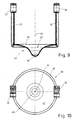
- Figs. 9 to 11 show a designated for the mast water collecting tray 46, the itself from the water collecting tray 24 in the formation of the water receiving trough 26th different.
- the support arms 32 are formed as in the water collecting tray 24, have in particular the same distances and the same clip closures 33, so that the water collecting tray 46 at the same location of the water supply line 20th can be attached, which serves to attach the water collecting tray 24.
- the water receiving trough 47 of the water collecting tray 46 has starting from the lowest point 48 to the upper edge 49 over a same cross-sectional shape.
- the water receiving trough 47 via the entire height circular cross-sectional shapes. It just changes to the edge 49 towards the diameter of the water receiving trough 47, namely, increases. However, the diameter increases to the depth of the water receiving trough 47th disproportionately, in such a way that the upper edge 49 towards the Diameter enlarged faster.
- the water collecting tray 46 has due to the continuous circular cross-sectional shape over a larger water absorption capacity as the water collecting tray 24. Thus, the water collecting tray is suitable 46 especially for older animals with a larger water requirement.
- the lowest point 48 of the water receiving trough 47 of the water collecting tray 46 can have a greater distance from the water supply line 20 than the deepest Position 27 of the water collecting tray 24. This has the lower end 45 of the tube 35 of the actuating lever 25 a greater distance to the lowest point 48 of the Wasserfactmulde 47 than that of the water collecting tray 24 is the case. Due to this, the operating lever 25 can be turned by a larger angle be pivoted, whereby a larger amount of water per unit time of respective drinking valve 21 is discharged without the need for the feeding valve 21st would have to be replaced.
- the two different water traps 24 and 46 allow a simple conversion of the animal cabinets. Such a conversion takes place for example in Infants of young animals, namely chicks. Then the animal cabinets with operating levers 25 and boat-like water collecting trays 24 provided. In one of the Rearing phase subsequent fattening phase of the animals will then enlarge Water requirement of the animals according to the invention thereby taken into account that the Water collecting trays 24 exchanged with smaller water absorption capacity be against water collecting trays 46 with greater water capacity. To do this only the clip closures 33 on the support arms 32 of the water collecting trays 24th opened and the water collecting trays 24 from the water supply line 20th separated. Subsequently, the water collecting trays 46 are in the same places attached to the water supply line 20. Conversely, after the Mast phase again the smaller water collecting trays 24 on the water supply line to be assembled.
- the actuating lever 25 or 50 at least partially Dismount by their locking connections from the mounting part 39 on the Water supply line 20 or from the operating end 23 of the valve pin triggers.
- the animal cabinets shown in FIG. 1 are modified so that each one second operating lever 25 is removed. Larger animals can then use the watering valves 21 open directly at the operating ends 23 of the valve pins. The animals can tilt the valve pin to the maximum possible extent and in the presence corresponding drinking valves 21 even lift the valve pins, creating a the greatest possible amount of water per unit of time can flow out of the feeding valve 21.
Landscapes
- Life Sciences & Earth Sciences (AREA)
- Environmental Sciences (AREA)
- Animal Husbandry (AREA)
- Biodiversity & Conservation Biology (AREA)
- Birds (AREA)
- Feeding And Watering For Cattle Raising And Animal Husbandry (AREA)
- Devices For Dispensing Beverages (AREA)
- Jigging Conveyors (AREA)
- Non-Alcoholic Beverages (AREA)
Abstract
Description
- Fig. 1
- eine Seitenansicht eines Teils der Tiertränke (Tränkeelement),
- Fig. 2
- eine vergrößerte Einzelheit II der Tiertränke die Fig. 1 in einem Teilschnitt,
- Fig. 3
- eine Darstellung der Tiertränke analog zur Fig. 2 in einem anderen Teilschnitt,
- Fig. 4
- einen Querschnitt durch die Tiertränke der Fig. 1,
- Fig. 5
- eine alternative Tiertränke mit einem stangenartigen Betätigungsmittel in einer Ansicht analog zur Fig. 2,
- Fig. 6
- eine Seitenansicht einer zur Aufzucht (bis zu sechs Wochen) dienenden Wasserauffangschale mit mittig geschnittener Wasseraufnahmemulde,
- Fig. 7
- eine Draufsicht auf die Wasserauffangschale in der Fig. 5,
- Fig. 8
- eine Seitenansicht der Wasserauffangschale der Fig. 5 und 6,
- Fig. 9
- eine für die Mast vorgesehene Wasserauffangschale mit einer größeren Wasseraufnahmekapazität in einer Seitenansicht,
- Fig. 10
- eine Draufsicht auf die Wasserauffangschale in der Fig. 9, und
- Fig. 11
- eine Seitenansicht der Wasserauffangschale der Fig. 8 und 9.
- 19
- Tränkestelle
- 20
- Wasserversorgungsleitung
- 21
- Tränkeventil
- 22
- Gehäuse
- 23
- Betätigungsende
- 24
- Wasserauffangschale
- 25
- Betätigungshebel
- 26
- Wasseraufnahmemulde
- 27
- tiefste Stelle
- 28
- Rand
- 29
- längere Achse
- 30
- kürzere Achse
- 31
- Längsmittelachse
- 32
- Tragarm
- 33
- Clipverschluss
- 34
- Gelenkteil
- 35
- Rohr
- 36
- Schwenkachse
- 37
- Schenkel
- 38
- Druchgangsbohrung
- 39
- Befestigungsteil
- 40
- Clipverschluss
- 41
- Achsstummel
- 42
- Steg
- 43
- Durchgangsbohrung
- 44
- Rippe
- 45
- unteres Ende
- 46
- Wasserauffangschale
- 47
- Wasseraufnahmemulde
- 48
- tiefste Stelle
- 49
- Rand
- 50
- Betätigungshebel
- 51
- freies Ende
- 52
- Spirale
Claims (16)
- Tiertränke für insbesondere Geflügel, wie Puten, Hühner, Küken oder dergleichen, mit mindestens einem einer Wasserversorgungsleitung (20) zugeordneten Tränkeventil (21), das einen zur Wasserabgabe bewegbaren Ventilstift aufweist, und mit mindestens einer dem jeweiligen Tränkeventil (21) zugeordneten Wasserauffangschale (24, 46), dadurch gekennzeichnet, dass dem Ventilstift ein Betätigungsmittel zugeordnet ist.
- Tiertränke nach Anspruch 1, dadurch gekennzeichnet, dass das Betätigungsmittel dem Ventilstift derart zugeordnet ist, dass durch eine Bewegung des Betätigungsmittels der Ventilstift in eine die Wasserabgabe aus dem Tränkeventil (21) zulassende Stellung beweglich ist.
- Tiertränke nach Anspruch 1 oder 2, dadurch gekennzeichnet, dass das Betätigungsmittel schwenkbar ausgebildet ist, insbesondere um eine feststehende Schwenkachse (36) verschwenkbar ist, wobei die Schwenkachse (36) relativ zum Tränkeventil (21) ortsunveränderlich ist, und vorzugsweise quer durch eine Längsmittelachse des Tränkeventils (21) bzw. des Ventilstifts verläuft, insbesondere etwa horizontal gerichtet quer zur Längsachse der Wasserversorgungsleitung (20) verläuft.
- Tiertränke nach einem der vorhergehenden Ansprüche, dadurch gekennzeichnet, dass die Schwenkachse (36) integraler Bestandteil eines Befestigungsteils (39) ist, das vorzugsweise lösbar mit der Wasserversorgungsleitung (20) verbunden ist.
- Tiertränke nach einem der vorhergehenden Ansprüche, dadurch gekennzeichnet, dass das vom Tränkeventil (21) abgegebene Wasser innen durch das Betätigungsmittel strömt, wobei vorzugsweise das Betätigungsmittel als ein länglicher Betätigungshebel (25) ausgebildet ist, der ein längliches Rohr (35) aufweist, durch das das vom Tränkeventil (21) abgegebene Wasser hindurchströmt.
- Tiertränke nach einem der vorhergehenden Ansprüche, dadurch gekennzeichnet, dass das Betätigungsmittel als ein fest mit einem Betätigungsende (23) des Ventilstifts verbundener stangenartiger Betätigungshebel (25) ausgebildet ist, an dem außen vom Tränkeventil abgegebenes Wasser entlangströmt.
- Tiertränke nach einem der vorhergehenden Ansprüche, dadurch gekennzeichnet, dass ein oberer Endbereich des Betätigungshebels (25), insbesondere des Rohrs (35), derart einem aus einem Gehäuse (22) des Tränkeventils (21) herausragenden Betätigungsende (23) des Ventilstifts zugeordnet ist, dass durch Verschwenken des Betätigungshebels (25) der Ventilstift zum Öffnen des Tränkeventils (21) verschwenkbar ist, und vorzugsweise der Betätigungshebel (25) im Bereich eines oberen Endes des Rohres (35) an das Betätigungsende (23) des Ventilstifts des Tränkeventils (21) angekuppelbar ist.
- Tiertränke nach einem der vorhergehenden Ansprüche, dadurch gekennzeichnet, dass der Betätigungshebel (25) derart um die Schwenkachse (36) kippbar an der Wasserversorgungsleitung (20) gelagert ist, dass der Betätigungshebel (25) selbständig, insbesondere schwerkraftbedingt, in eine vorzugsweise senkrechte Stellung zurückkehrt in der der Ventilstift unbetätigt und das Tränkeventil (21) geschlossen ist.
- Tiertränke nach einem der vorhergehenden Ansprüche, dadurch gekennzeichnet, dass ein unteres Ende des Betätigungsmittels sich bis in eine Wasseraufnahmemulde (26, 47) der Wasserauffangschale (24, 46) hinein erstreckt.
- Tiertränke für insbesondere Geflügel, wie Puten, Hühner, Küken oder dergleichen mit mindestens einem einer Wasserversorgungsleitung (20) zugeordneten Tränkeventil (21) und mit mindestens eine dem Tränkeventil (21) zugeordneten Wasserauffangschale (24) mit einer oben offenen Wasseraufnahmemulde (26), dadurch gekennzeichnet, dass die Wasseraufnahmemulde (26) sich mit dem Wasserstand ändernde Querschnittsformen aufweist.
- Tiertränke nach einem der vorhergehenden Ansprüche, dadurch gekennzeichnet, dass die Wasseraufnahmemulde (26) in der Nähe ihres Bodens einen etwa kreisrunden Querschnitt aufweist und darüber der Querschnitt der Wasseraufnahmemulde (26) unrund, vorzugsweise elliptisch bzw. oval, ist, wobei vorzugsweise der unrunde Querschnitt der Wasseraufnahmemulde sich zu einem oberen Rand (28) hin vergrößert, und sich dabei gegebenenfalls das Verhältnis der längeren Achse (29) zur kürzeren Achse (30) des ovalen bzw. elliptischen Querschnitts vergrößert.
- Tiertränke nach einem der vorhergehenden Ansprüche, dadurch gekennzeichnet, dass eine im Querschnitt längliche, insbesondere ovale bzw. elliptische obere Öffnung, die vom Rand (28) der Wasseraufnahmemulde (26) umgeben ist, sich längs zur länglichen Wasserversorgungsleitung (29) erstreckt.
- Tiertränke nach einem der vorhergehenden Ansprüche, dadurch gekennzeichnet, dass die Wasserauffangschale (24) an jeder ihrer Schmalseiten einen Tragarm (32) aufweist und jeder Tragarm (32) am oberen Ende ein Kupplungsmittel zur lösbaren, aber relativ zur Wasserversorgungsleitung unbeweglichen Verbindung der Tragarme (32) mit der Wasserversorgungsleitung (20) aufweist.
- Tiertränke nach einem der vorhergehenden Ansprüche, dadurch gekennzeichnet, dass die Wasseraufnahmemulde (26) der Wasserauffangschale (24) sowie die Länge und/oder der Durchmesser des Rohrs (35) des Betätigungshebels (25) so bemessen bzw. aufeinander abgestimmt sind, dass durch ein unteres Ende (45) des Rohrs (35) der Schwenkwinkel des Betätigungshebels (25) festlegbar.bzw. begrenzbar ist.
- Verfahren zur Umrüstung einer Tiertränke, die mindestens ein mit einer Wasserversorgungsleitung (20) verbundenes Tränkeventil (21) und mindestens eine dem Tränkeventil (21) zugeordnete Wasserauffangschale (24, 46) aufweist, dadurch gekennzeichnet, dass eine für junge Tiere vorgesehene Wasserauffangschale (24) mit einer begrenzten Wasseraufnahmekapazität ab Erreichen eines bestimmten Alters der Tiere ausgetauscht wird gegen eine Wasserauffangschale (46) mit einer größeren Wasseraufnahmekapazität.
- Verfahren nach Anspruch 15, dadurch gekennzeichnet, dass mit dem Austausch der Wasserauffangschale (24; 46) die maximale Wasseraustrittsmenge pro Zeiteinheit aus dem jeweiligen Tränkeventil (21) verändert wird, vorzugsweise die Wasserauffangschale (46) mit einer größeren Wasseraufnahmekapazität eine pro Zeiteinheit größere Wasseraustrittsmenge aus dem Tränkeventil (21) zulässt.
Applications Claiming Priority (4)
| Application Number | Priority Date | Filing Date | Title |
|---|---|---|---|
| DE10153595 | 2001-11-02 | ||
| DE10153595 | 2001-11-02 | ||
| DE10215696A DE10215696A1 (de) | 2001-11-02 | 2002-04-10 | Tiertränke und Verfahren zur Umrüstung derselben |
| DE10215696 | 2002-04-10 |
Publications (3)
| Publication Number | Publication Date |
|---|---|
| EP1308089A2 true EP1308089A2 (de) | 2003-05-07 |
| EP1308089A3 EP1308089A3 (de) | 2003-10-22 |
| EP1308089B1 EP1308089B1 (de) | 2006-04-19 |
Family
ID=26010489
Family Applications (1)
| Application Number | Title | Priority Date | Filing Date |
|---|---|---|---|
| EP02023938A Expired - Lifetime EP1308089B1 (de) | 2001-11-02 | 2002-10-25 | Tiertränke |
Country Status (6)
| Country | Link |
|---|---|
| US (1) | US6938578B2 (de) |
| EP (1) | EP1308089B1 (de) |
| AT (1) | ATE323407T1 (de) |
| DE (1) | DE50206453D1 (de) |
| ES (1) | ES2261577T3 (de) |
| PT (1) | PT1308089E (de) |
Cited By (3)
| Publication number | Priority date | Publication date | Assignee | Title |
|---|---|---|---|---|
| EP1862068A1 (de) * | 2006-05-29 | 2007-12-05 | LUBING Maschinenfabrik Ludwig Bening GmbH & Co. KG | Tiertränke und Wasserauffangschale für eine Tiertränke |
| US20180116174A1 (en) * | 2016-11-02 | 2018-05-03 | Barnstorfer Kunststofftechnik Gmbh & Co. Kg | Animal drinker and drip cup for an animal drinker |
| IT202000001624A1 (it) | 2020-01-28 | 2021-07-28 | Corti Zootecnici S R L | Abbeveratoio automatico per volatili di allevamento |
Families Citing this family (4)
| Publication number | Priority date | Publication date | Assignee | Title |
|---|---|---|---|---|
| USD663488S1 (en) * | 2010-03-10 | 2012-07-10 | Lubing Maschinenfabrik Ludwig Bening Gmbh & Co. Kg | Pipeline |
| DE102013002394A1 (de) * | 2013-02-13 | 2014-08-14 | Lubing Maschinenfabrik Ludwig Bening Gmbh & Co. Kg | Tiertränke |
| DE102017011041A1 (de) * | 2017-11-29 | 2019-05-29 | ''LUBING'' Maschinenfabrik Ludwig Bening GmbH & Co. Kommanditgesellschaft | Tiertränke, insbesondere für Schnabeltiere |
| USD879388S1 (en) * | 2017-12-08 | 2020-03-24 | Marc Song | Poultry water dispenser |
Family Cites Families (28)
| Publication number | Priority date | Publication date | Assignee | Title |
|---|---|---|---|---|
| US1743719A (en) * | 1927-04-23 | 1930-01-14 | Louden Machinery Co | Animal water bowl |
| US2845046A (en) * | 1955-09-26 | 1958-07-29 | Harold W Hart | Water supplying device for poultry |
| US3357406A (en) * | 1966-03-29 | 1967-12-12 | John C Robinson | Livestock watering device |
| US3428028A (en) * | 1967-01-05 | 1969-02-18 | Hart Mfg Co H W | Drinking cup for fowls |
| FR1536664A (fr) * | 1967-09-11 | 1968-08-16 | Abreuvoirs hygiéniques pour volailles | |
| US3483847A (en) * | 1968-04-23 | 1969-12-16 | Herman J Kneubuehl | Poultry water cup and valve |
| GB1321644A (en) * | 1970-07-01 | 1973-06-27 | Mallinson R I | Valves for controlling the supply of drinking water to poultry and other livestock |
| DE7031234U (de) * | 1970-08-20 | 1970-12-03 | Lubing Maschf Ludwig | Traenkeventil mit auffangschale fuer kleintiere, zum beispiel huehner. |
| US3734063A (en) * | 1971-08-03 | 1973-05-22 | F Atchley | Demand delivery watering valve for animals |
| US3756199A (en) * | 1972-04-17 | 1973-09-04 | Fox Prod Co | Animal operated watering device |
| GB1566746A (en) * | 1977-12-02 | 1980-05-08 | Mono Flo Nipple Drinkers Ltd | Drinkers for livestock |
| FR2413874A1 (fr) * | 1978-01-04 | 1979-08-03 | Buvette Sa | Perfectionnements aux abreuvoirs automatiques |
| US4637345A (en) * | 1980-01-21 | 1987-01-20 | Ziggity Systems, Inc. | Watering system for fowl and small animals |
| IL64499A (en) * | 1981-01-16 | 1984-12-31 | Plasson Maagan Michael Ind Ltd | Poultry watering device |
| US4338884A (en) * | 1981-03-09 | 1982-07-13 | Atco Manufacturing Co., Inc. | Animal bite valve |
| US4606301A (en) * | 1984-04-02 | 1986-08-19 | Val Products, Inc. | Nipple for feeding liquids to fowl and/or small animals |
| US4538791A (en) * | 1984-04-10 | 1985-09-03 | Norse Leasing Corp. | Valve mechanism for a livestock watering bowl |
| DE8804053U1 (de) | 1988-02-18 | 1988-06-01 | Lubing Maschinenfabrik Ludwig Bening Gmbh & Co Kg, 2847 Barnstorf | Tränkeventil |
| DE8904359U1 (de) * | 1989-04-07 | 1990-08-09 | Hans Neher GmbH & Co KG, 6292 Weilmünster | Schnellverbindung für Kleintiertränken |
| US5074250A (en) * | 1990-03-02 | 1991-12-24 | Clark Iv Reuben B | Animal-operated watering device |
| DE9101513U1 (de) | 1991-02-09 | 1991-05-02 | Lubing Maschinenfabrik Ludwig Bening Gmbh & Co Kg, 2847 Barnstorf | Tränkeventil für Kleintiere, insbesondere Hühner |
| US5245950A (en) * | 1991-06-11 | 1993-09-21 | Shenandoah Manufacturing Co., Inc. | Poultry watering system |
| DE4203451A1 (de) | 1992-02-07 | 1993-08-12 | Neher Hans Gmbh & Co Kg | Kleintiertraenkeventil |
| DE9207415U1 (de) | 1992-02-08 | 1992-08-27 | Lubing Maschinenfabrik Ludwig Bening Gmbh & Co Kg, 2847 Barnstorf | Strangtränke zur Wasserversorgung von Tieren |
| DE19712748C2 (de) * | 1997-03-26 | 2002-09-19 | Lubing Maschf Ludwig | Tränkeventil |
| DE19830586B4 (de) * | 1998-07-08 | 2007-03-08 | Lubing Maschinenfabrik Ludwig Bening Gmbh & Co. Kg | Tränkeventil |
| PL186308B1 (pl) * | 1999-03-01 | 2003-12-31 | Niesiobedzki Tadeusz | Poidło dla drobiu |
| NL1015680C2 (nl) * | 2000-07-11 | 2002-01-14 | Roxell Nv | Drinksysteem voor het te drinken geven van gevogelte. |
-
2002
- 2002-10-25 AT AT02023938T patent/ATE323407T1/de not_active IP Right Cessation
- 2002-10-25 EP EP02023938A patent/EP1308089B1/de not_active Expired - Lifetime
- 2002-10-25 PT PT02023938T patent/PT1308089E/pt unknown
- 2002-10-25 DE DE50206453T patent/DE50206453D1/de not_active Expired - Lifetime
- 2002-10-25 ES ES02023938T patent/ES2261577T3/es not_active Expired - Lifetime
- 2002-10-29 US US10/282,788 patent/US6938578B2/en not_active Expired - Lifetime
Cited By (4)
| Publication number | Priority date | Publication date | Assignee | Title |
|---|---|---|---|---|
| EP1862068A1 (de) * | 2006-05-29 | 2007-12-05 | LUBING Maschinenfabrik Ludwig Bening GmbH & Co. KG | Tiertränke und Wasserauffangschale für eine Tiertränke |
| US8069818B2 (en) | 2006-05-29 | 2011-12-06 | Lubing Maschinenfabrik Ludwig Bening Gmbh & Co. Kg | Drinking trough for animals and water-collecting bowl for a drinking trough for animals |
| US20180116174A1 (en) * | 2016-11-02 | 2018-05-03 | Barnstorfer Kunststofftechnik Gmbh & Co. Kg | Animal drinker and drip cup for an animal drinker |
| IT202000001624A1 (it) | 2020-01-28 | 2021-07-28 | Corti Zootecnici S R L | Abbeveratoio automatico per volatili di allevamento |
Also Published As
| Publication number | Publication date |
|---|---|
| US20030084854A1 (en) | 2003-05-08 |
| EP1308089B1 (de) | 2006-04-19 |
| DE50206453D1 (de) | 2006-05-24 |
| ATE323407T1 (de) | 2006-05-15 |
| ES2261577T3 (es) | 2006-11-16 |
| US6938578B2 (en) | 2005-09-06 |
| EP1308089A3 (de) | 2003-10-22 |
| PT1308089E (pt) | 2006-08-31 |
Similar Documents
| Publication | Publication Date | Title |
|---|---|---|
| EP1458231B1 (de) | Vorrichtung für die fütterung von geflügel, insbesondere mastgeflügel, vorzugsweise broiler | |
| DE10164122C1 (de) | Vorrichtung für die Fütterung von Geflügel, insbesondere Mastgeflügel, vorzugsweise Broiler | |
| DE60102921T2 (de) | Selbsttättige fütterungsvorrichtung | |
| EP2767158B1 (de) | Tiertränke | |
| DE3113183A1 (de) | Selbsttaetige traenke | |
| EP1862068A1 (de) | Tiertränke und Wasserauffangschale für eine Tiertränke | |
| EP1308089B1 (de) | Tiertränke | |
| DE69527647T2 (de) | Fütterungseinrichtung, insbesondere für schweine | |
| EP0524281A1 (de) | Tränkeventil für kleintiere, insbesondere hühner | |
| DE3701528C2 (de) | ||
| DE1903791U (de) | Gefluegeltraenke mit freihaengendem trinkgefaess und selbsttaetigem fuellventil. | |
| DE202014008421U1 (de) | Tiertränke und Wasserauffangschale für eine Tiertränke | |
| DE2328902A1 (de) | Traenkbecher fuer gefluegel | |
| DE19934577C1 (de) | Tränke für Großvieh | |
| EP3716758B1 (de) | Tiertränke, insbesondere für schnabeltiere | |
| DE60106257T2 (de) | Trinkanlage zum Versorgen von Geflügel mit Trinkflüssigkeit | |
| DE10215696A1 (de) | Tiertränke und Verfahren zur Umrüstung derselben | |
| DE202005020411U1 (de) | Tiertränke und Wasserauffangschale für eine Tiertränke | |
| DE3202246C2 (de) | ||
| DE102014004542B4 (de) | Strangtränke zur Wasserversorgung von Tieren | |
| DE2213410B2 (de) | Viehselbsttränkebecken | |
| DE3202756A1 (de) | Futterzuteilungsvorrichtung, insbesondere fuer schweinebuchten und sauenkaefige | |
| DE8219720U1 (de) | Gefluegeltraenke | |
| WO2023227153A1 (de) | Vorrichtung zur bereitstellung einer flüssigkeit für nutzgeflügel | |
| DE6800138U (de) | Selbsttraenkevorrichtung fuer tiere |
Legal Events
| Date | Code | Title | Description |
|---|---|---|---|
| PUAI | Public reference made under article 153(3) epc to a published international application that has entered the european phase |
Free format text: ORIGINAL CODE: 0009012 |
|
| AK | Designated contracting states |
Designated state(s): AT BE BG CH CY CZ DE DK EE ES FI FR GB GR IE IT LI LU MC NL PT SE SK TR |
|
| AX | Request for extension of the european patent |
Extension state: AL LT LV MK RO SI |
|
| RIC1 | Information provided on ipc code assigned before grant |
Ipc: 7A 01K 7/06 B Ipc: 7A 01K 39/02 A |
|
| PUAL | Search report despatched |
Free format text: ORIGINAL CODE: 0009013 |
|
| AK | Designated contracting states |
Kind code of ref document: A3 Designated state(s): AT BE BG CH CY CZ DE DK EE ES FI FR GB GR IE IT LI LU MC NL PT SE SK TR |
|
| AX | Request for extension of the european patent |
Extension state: AL LT LV MK RO SI |
|
| 17P | Request for examination filed |
Effective date: 20040407 |
|
| AKX | Designation fees paid |
Designated state(s): AT BE BG CH CY CZ DE DK EE ES FI FR GB GR IE IT LI LU MC NL PT SE SK TR |
|
| 17Q | First examination report despatched |
Effective date: 20040628 |
|
| GRAP | Despatch of communication of intention to grant a patent |
Free format text: ORIGINAL CODE: EPIDOSNIGR1 |
|
| RTI1 | Title (correction) |
Free format text: ANIMAL DRINKER |
|
| GRAS | Grant fee paid |
Free format text: ORIGINAL CODE: EPIDOSNIGR3 |
|
| GRAA | (expected) grant |
Free format text: ORIGINAL CODE: 0009210 |
|
| AK | Designated contracting states |
Kind code of ref document: B1 Designated state(s): AT BE BG CH CY CZ DE DK EE ES FI FR GB GR IE IT LI LU MC NL PT SE SK TR |
|
| PG25 | Lapsed in a contracting state [announced via postgrant information from national office to epo] |
Ref country code: IT Free format text: LAPSE BECAUSE OF FAILURE TO SUBMIT A TRANSLATION OF THE DESCRIPTION OR TO PAY THE FEE WITHIN THE PRESCRIBED TIME-LIMIT;WARNING: LAPSES OF ITALIAN PATENTS WITH EFFECTIVE DATE BEFORE 2007 MAY HAVE OCCURRED AT ANY TIME BEFORE 2007. THE CORRECT EFFECTIVE DATE MAY BE DIFFERENT FROM THE ONE RECORDED. Effective date: 20060419 Ref country code: SK Free format text: LAPSE BECAUSE OF FAILURE TO SUBMIT A TRANSLATION OF THE DESCRIPTION OR TO PAY THE FEE WITHIN THE PRESCRIBED TIME-LIMIT Effective date: 20060419 Ref country code: FI Free format text: LAPSE BECAUSE OF FAILURE TO SUBMIT A TRANSLATION OF THE DESCRIPTION OR TO PAY THE FEE WITHIN THE PRESCRIBED TIME-LIMIT Effective date: 20060419 Ref country code: IE Free format text: LAPSE BECAUSE OF FAILURE TO SUBMIT A TRANSLATION OF THE DESCRIPTION OR TO PAY THE FEE WITHIN THE PRESCRIBED TIME-LIMIT Effective date: 20060419 Ref country code: CZ Free format text: LAPSE BECAUSE OF FAILURE TO SUBMIT A TRANSLATION OF THE DESCRIPTION OR TO PAY THE FEE WITHIN THE PRESCRIBED TIME-LIMIT Effective date: 20060419 |
|
| REG | Reference to a national code |
Ref country code: GB Ref legal event code: FG4D Free format text: NOT ENGLISH |
|
| REF | Corresponds to: |
Ref document number: 50206453 Country of ref document: DE Date of ref document: 20060524 Kind code of ref document: P |
|
| REG | Reference to a national code |
Ref country code: IE Ref legal event code: FG4D Free format text: LANGUAGE OF EP DOCUMENT: GERMAN |
|
| PG25 | Lapsed in a contracting state [announced via postgrant information from national office to epo] |
Ref country code: DK Free format text: LAPSE BECAUSE OF FAILURE TO SUBMIT A TRANSLATION OF THE DESCRIPTION OR TO PAY THE FEE WITHIN THE PRESCRIBED TIME-LIMIT Effective date: 20060719 Ref country code: SE Free format text: LAPSE BECAUSE OF FAILURE TO SUBMIT A TRANSLATION OF THE DESCRIPTION OR TO PAY THE FEE WITHIN THE PRESCRIBED TIME-LIMIT Effective date: 20060719 |
|
| REG | Reference to a national code |
Ref country code: PT Ref legal event code: SC4A Effective date: 20060713 |
|
| GBT | Gb: translation of ep patent filed (gb section 77(6)(a)/1977) |
Effective date: 20060814 |
|
| PG25 | Lapsed in a contracting state [announced via postgrant information from national office to epo] |
Ref country code: MC Free format text: LAPSE BECAUSE OF NON-PAYMENT OF DUE FEES Effective date: 20061031 Ref country code: LI Free format text: LAPSE BECAUSE OF NON-PAYMENT OF DUE FEES Effective date: 20061031 Ref country code: CH Free format text: LAPSE BECAUSE OF NON-PAYMENT OF DUE FEES Effective date: 20061031 |
|
| REG | Reference to a national code |
Ref country code: IE Ref legal event code: FD4D |
|
| REG | Reference to a national code |
Ref country code: ES Ref legal event code: FG2A Ref document number: 2261577 Country of ref document: ES Kind code of ref document: T3 |
|
| ET | Fr: translation filed | ||
| PLBE | No opposition filed within time limit |
Free format text: ORIGINAL CODE: 0009261 |
|
| STAA | Information on the status of an ep patent application or granted ep patent |
Free format text: STATUS: NO OPPOSITION FILED WITHIN TIME LIMIT |
|
| 26N | No opposition filed |
Effective date: 20070122 |
|
| REG | Reference to a national code |
Ref country code: CH Ref legal event code: PL |
|
| BERE | Be: lapsed |
Owner name: LUBING MASCHINENFABRIK LUDWIG BENING G.M.B.H. & CO Effective date: 20061031 |
|
| PG25 | Lapsed in a contracting state [announced via postgrant information from national office to epo] |
Ref country code: AT Free format text: LAPSE BECAUSE OF NON-PAYMENT OF DUE FEES Effective date: 20061025 |
|
| PG25 | Lapsed in a contracting state [announced via postgrant information from national office to epo] |
Ref country code: GR Free format text: LAPSE BECAUSE OF FAILURE TO SUBMIT A TRANSLATION OF THE DESCRIPTION OR TO PAY THE FEE WITHIN THE PRESCRIBED TIME-LIMIT Effective date: 20060720 |
|
| PG25 | Lapsed in a contracting state [announced via postgrant information from national office to epo] |
Ref country code: BG Free format text: LAPSE BECAUSE OF FAILURE TO SUBMIT A TRANSLATION OF THE DESCRIPTION OR TO PAY THE FEE WITHIN THE PRESCRIBED TIME-LIMIT Effective date: 20060719 Ref country code: EE Free format text: LAPSE BECAUSE OF FAILURE TO SUBMIT A TRANSLATION OF THE DESCRIPTION OR TO PAY THE FEE WITHIN THE PRESCRIBED TIME-LIMIT Effective date: 20060419 |
|
| PG25 | Lapsed in a contracting state [announced via postgrant information from national office to epo] |
Ref country code: TR Free format text: LAPSE BECAUSE OF FAILURE TO SUBMIT A TRANSLATION OF THE DESCRIPTION OR TO PAY THE FEE WITHIN THE PRESCRIBED TIME-LIMIT Effective date: 20060419 Ref country code: LU Free format text: LAPSE BECAUSE OF NON-PAYMENT OF DUE FEES Effective date: 20061025 |
|
| PG25 | Lapsed in a contracting state [announced via postgrant information from national office to epo] |
Ref country code: CY Free format text: LAPSE BECAUSE OF FAILURE TO SUBMIT A TRANSLATION OF THE DESCRIPTION OR TO PAY THE FEE WITHIN THE PRESCRIBED TIME-LIMIT Effective date: 20060419 |
|
| PG25 | Lapsed in a contracting state [announced via postgrant information from national office to epo] |
Ref country code: BE Free format text: LAPSE BECAUSE OF FAILURE TO SUBMIT A TRANSLATION OF THE DESCRIPTION OR TO PAY THE FEE WITHIN THE PRESCRIBED TIME-LIMIT Effective date: 20061031 |
|
| REG | Reference to a national code |
Ref country code: FR Ref legal event code: PLFP Year of fee payment: 14 |
|
| REG | Reference to a national code |
Ref country code: FR Ref legal event code: PLFP Year of fee payment: 15 |
|
| PGFP | Annual fee paid to national office [announced via postgrant information from national office to epo] |
Ref country code: ES Payment date: 20160927 Year of fee payment: 15 |
|
| PGFP | Annual fee paid to national office [announced via postgrant information from national office to epo] |
Ref country code: DE Payment date: 20161025 Year of fee payment: 15 Ref country code: GB Payment date: 20161019 Year of fee payment: 15 Ref country code: NL Payment date: 20161010 Year of fee payment: 15 |
|
| PGFP | Annual fee paid to national office [announced via postgrant information from national office to epo] |
Ref country code: PT Payment date: 20161017 Year of fee payment: 15 |
|
| REG | Reference to a national code |
Ref country code: FR Ref legal event code: PLFP Year of fee payment: 16 |
|
| REG | Reference to a national code |
Ref country code: DE Ref legal event code: R119 Ref document number: 50206453 Country of ref document: DE |
|
| REG | Reference to a national code |
Ref country code: NL Ref legal event code: MM Effective date: 20171101 |
|
| GBPC | Gb: european patent ceased through non-payment of renewal fee |
Effective date: 20171025 |
|
| PG25 | Lapsed in a contracting state [announced via postgrant information from national office to epo] |
Ref country code: GB Free format text: LAPSE BECAUSE OF NON-PAYMENT OF DUE FEES Effective date: 20171025 Ref country code: NL Free format text: LAPSE BECAUSE OF NON-PAYMENT OF DUE FEES Effective date: 20171101 Ref country code: PT Free format text: LAPSE BECAUSE OF NON-PAYMENT OF DUE FEES Effective date: 20180426 Ref country code: DE Free format text: LAPSE BECAUSE OF NON-PAYMENT OF DUE FEES Effective date: 20180501 |
|
| REG | Reference to a national code |
Ref country code: FR Ref legal event code: PLFP Year of fee payment: 17 |
|
| REG | Reference to a national code |
Ref country code: ES Ref legal event code: FD2A Effective date: 20181221 |
|
| PG25 | Lapsed in a contracting state [announced via postgrant information from national office to epo] |
Ref country code: ES Free format text: LAPSE BECAUSE OF NON-PAYMENT OF DUE FEES Effective date: 20171026 |
|
| PGFP | Annual fee paid to national office [announced via postgrant information from national office to epo] |
Ref country code: FR Payment date: 20190927 Year of fee payment: 18 |
|
| PGFP | Annual fee paid to national office [announced via postgrant information from national office to epo] |
Ref country code: IT Payment date: 20191009 Year of fee payment: 18 |
|
| PG25 | Lapsed in a contracting state [announced via postgrant information from national office to epo] |
Ref country code: FR Free format text: LAPSE BECAUSE OF NON-PAYMENT OF DUE FEES Effective date: 20201031 |
|
| PG25 | Lapsed in a contracting state [announced via postgrant information from national office to epo] |
Ref country code: IT Free format text: LAPSE BECAUSE OF NON-PAYMENT OF DUE FEES Effective date: 20201025 |