EP1308351A1 - Dispositif de support pour un boítier de capteur radar ajustable - Google Patents
Dispositif de support pour un boítier de capteur radar ajustable Download PDFInfo
- Publication number
- EP1308351A1 EP1308351A1 EP02020861A EP02020861A EP1308351A1 EP 1308351 A1 EP1308351 A1 EP 1308351A1 EP 02020861 A EP02020861 A EP 02020861A EP 02020861 A EP02020861 A EP 02020861A EP 1308351 A1 EP1308351 A1 EP 1308351A1
- Authority
- EP
- European Patent Office
- Prior art keywords
- sensor housing
- adjustment
- housing
- holder according
- adjustable
- Prior art date
- Legal status (The legal status is an assumption and is not a legal conclusion. Google has not performed a legal analysis and makes no representation as to the accuracy of the status listed.)
- Granted
Links
- 238000004891 communication Methods 0.000 claims description 2
- 238000009434 installation Methods 0.000 description 3
- 239000000725 suspension Substances 0.000 description 2
- 238000010276 construction Methods 0.000 description 1
- 230000002349 favourable effect Effects 0.000 description 1
- 238000004519 manufacturing process Methods 0.000 description 1
Images
Classifications
-
- G—PHYSICS
- G01—MEASURING; TESTING
- G01S—RADIO DIRECTION-FINDING; RADIO NAVIGATION; DETERMINING DISTANCE OR VELOCITY BY USE OF RADIO WAVES; LOCATING OR PRESENCE-DETECTING BY USE OF THE REFLECTION OR RERADIATION OF RADIO WAVES; ANALOGOUS ARRANGEMENTS USING OTHER WAVES
- G01S7/00—Details of systems according to groups G01S13/00, G01S15/00, G01S17/00
- G01S7/02—Details of systems according to groups G01S13/00, G01S15/00, G01S17/00 of systems according to group G01S13/00
- G01S7/40—Means for monitoring or calibrating
- G01S7/4004—Means for monitoring or calibrating of parts of a radar system
- G01S7/4026—Antenna boresight
- G01S7/403—Antenna boresight in azimuth, i.e. in the horizontal plane
-
- G—PHYSICS
- G01—MEASURING; TESTING
- G01S—RADIO DIRECTION-FINDING; RADIO NAVIGATION; DETERMINING DISTANCE OR VELOCITY BY USE OF RADIO WAVES; LOCATING OR PRESENCE-DETECTING BY USE OF THE REFLECTION OR RERADIATION OF RADIO WAVES; ANALOGOUS ARRANGEMENTS USING OTHER WAVES
- G01S7/00—Details of systems according to groups G01S13/00, G01S15/00, G01S17/00
- G01S7/02—Details of systems according to groups G01S13/00, G01S15/00, G01S17/00 of systems according to group G01S13/00
- G01S7/40—Means for monitoring or calibrating
- G01S7/4004—Means for monitoring or calibrating of parts of a radar system
- G01S7/4026—Antenna boresight
-
- G—PHYSICS
- G01—MEASURING; TESTING
- G01S—RADIO DIRECTION-FINDING; RADIO NAVIGATION; DETERMINING DISTANCE OR VELOCITY BY USE OF RADIO WAVES; LOCATING OR PRESENCE-DETECTING BY USE OF THE REFLECTION OR RERADIATION OF RADIO WAVES; ANALOGOUS ARRANGEMENTS USING OTHER WAVES
- G01S7/00—Details of systems according to groups G01S13/00, G01S15/00, G01S17/00
- G01S7/02—Details of systems according to groups G01S13/00, G01S15/00, G01S17/00 of systems according to group G01S13/00
- G01S7/40—Means for monitoring or calibrating
- G01S7/4004—Means for monitoring or calibrating of parts of a radar system
- G01S7/4026—Antenna boresight
- G01S7/4034—Antenna boresight in elevation, i.e. in the vertical plane
-
- B—PERFORMING OPERATIONS; TRANSPORTING
- B60—VEHICLES IN GENERAL
- B60R—VEHICLES, VEHICLE FITTINGS, OR VEHICLE PARTS, NOT OTHERWISE PROVIDED FOR
- B60R19/00—Wheel guards; Radiator guards, e.g. grilles; Obstruction removers; Fittings damping bouncing force in collisions
- B60R19/02—Bumpers, i.e. impact receiving or absorbing members for protecting vehicles or fending off blows from other vehicles or objects
- B60R19/48—Bumpers, i.e. impact receiving or absorbing members for protecting vehicles or fending off blows from other vehicles or objects combined with, or convertible into, other devices or objects, e.g. bumpers combined with road brushes, bumpers convertible into beds
- B60R19/483—Bumpers, i.e. impact receiving or absorbing members for protecting vehicles or fending off blows from other vehicles or objects combined with, or convertible into, other devices or objects, e.g. bumpers combined with road brushes, bumpers convertible into beds with obstacle sensors of electric or electronic type
-
- B—PERFORMING OPERATIONS; TRANSPORTING
- B60—VEHICLES IN GENERAL
- B60R—VEHICLES, VEHICLE FITTINGS, OR VEHICLE PARTS, NOT OTHERWISE PROVIDED FOR
- B60R21/00—Arrangements or fittings on vehicles for protecting or preventing injuries to occupants or pedestrians in case of accidents or other traffic risks
- B60R21/01—Electrical circuits for triggering passive safety arrangements, e.g. airbags, safety belt tighteners, in case of vehicle accidents or impending vehicle accidents
- B60R2021/01013—Means for detecting collision, impending collision or roll-over
- B60R2021/01027—Safing sensors
-
- G—PHYSICS
- G01—MEASURING; TESTING
- G01S—RADIO DIRECTION-FINDING; RADIO NAVIGATION; DETERMINING DISTANCE OR VELOCITY BY USE OF RADIO WAVES; LOCATING OR PRESENCE-DETECTING BY USE OF THE REFLECTION OR RERADIATION OF RADIO WAVES; ANALOGOUS ARRANGEMENTS USING OTHER WAVES
- G01S13/00—Systems using the reflection or reradiation of radio waves, e.g. radar systems; Analogous systems using reflection or reradiation of waves whose nature or wavelength is irrelevant or unspecified
- G01S13/88—Radar or analogous systems specially adapted for specific applications
- G01S13/93—Radar or analogous systems specially adapted for specific applications for anti-collision purposes
- G01S13/931—Radar or analogous systems specially adapted for specific applications for anti-collision purposes of land vehicles
-
- G—PHYSICS
- G01—MEASURING; TESTING
- G01S—RADIO DIRECTION-FINDING; RADIO NAVIGATION; DETERMINING DISTANCE OR VELOCITY BY USE OF RADIO WAVES; LOCATING OR PRESENCE-DETECTING BY USE OF THE REFLECTION OR RERADIATION OF RADIO WAVES; ANALOGOUS ARRANGEMENTS USING OTHER WAVES
- G01S13/00—Systems using the reflection or reradiation of radio waves, e.g. radar systems; Analogous systems using reflection or reradiation of waves whose nature or wavelength is irrelevant or unspecified
- G01S13/88—Radar or analogous systems specially adapted for specific applications
- G01S13/93—Radar or analogous systems specially adapted for specific applications for anti-collision purposes
- G01S13/931—Radar or analogous systems specially adapted for specific applications for anti-collision purposes of land vehicles
- G01S2013/9322—Radar or analogous systems specially adapted for specific applications for anti-collision purposes of land vehicles using additional data, e.g. driver condition, road state or weather data
-
- Y—GENERAL TAGGING OF NEW TECHNOLOGICAL DEVELOPMENTS; GENERAL TAGGING OF CROSS-SECTIONAL TECHNOLOGIES SPANNING OVER SEVERAL SECTIONS OF THE IPC; TECHNICAL SUBJECTS COVERED BY FORMER USPC CROSS-REFERENCE ART COLLECTIONS [XRACs] AND DIGESTS
- Y10—TECHNICAL SUBJECTS COVERED BY FORMER USPC
- Y10T—TECHNICAL SUBJECTS COVERED BY FORMER US CLASSIFICATION
- Y10T403/00—Joints and connections
- Y10T403/16—Joints and connections with adjunctive protector, broken parts retainer, repair, assembly or disassembly feature
- Y10T403/1616—Position or guide means
- Y10T403/1624—Related to joint component
Definitions
- the invention relates to a holder for an adjustable Housing, in particular for the housing of a radar sensor, which is attached to the outside of a motor vehicle, according to the preamble of the main claim.
- Such a radar sensor with a bracket screwed onto the outside of a vehicle can, for example, be a building block of a distance warning system be in the constant information about the Distance and / or the relative speed of the vehicle to other vehicles and the road conditions are processed. It is necessary here the radar sensor to align very precisely to the longitudinal axis of the vehicle, which due to the sometimes considerable vehicle tolerances in the area of the mounting point a horizontal one and vertical adjustment of the sensor after installation in the Motor vehicle is necessary.
- the at least one adjusting screw is here by means of a adjustable vertical drive is rotatable and for Adjustment of the housing, control electronics are available the adjustment signals to the respective adjustment drive () forwards.
- a plug connection is advantageous for a bus connection of the control unit electronics for Communication with a higher-level bus system, preferred a so-called CAN bus, available in one compact bracket housing the control electronics, the at least one adjustment drive and the plug connection are housed and only the attachment points the adjustment screws for the adjustable sensor housing protrude from the bracket housing.
- the at least one adjusting screw each via a rotating spindle with the adjustment drive for linear adjustment of the fastening points connected, the respective adjustment drive is a stepper motor or a DC motor.
- the holder housing is particularly advantageous made up of two arms at right angles to each other, each one linearly via an adjusting motor changeable fastening point for the sensor housing on End of each arm and third fixed attachment point lies at the intersection of the two arms.
- the invention can be used in a particularly compact structure the bracket an automatic adjustment with relative be carried out in a short amount of time, with the favorable construction of the bracket housing and not necessary access to the adjustment screws the installation position can be chosen very flexibly.
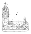
- bracket housing 1 for a radar sensor built-up distance sensor can be seen as in Principle known from the prior art mentioned at the outset is.
- the radar sensor not shown here, is for Attachment to a motor vehicle via the bracket housing 1 adjustable at three attachment points 2, 3 and 4 appropriate.
- the attachment points 2, 3 and 4 are the ends of adjusting screws, which due to their L-shaped arrangement form a three-point bearing, the attachment points 2 and 4 two floating bearings for horizontal and vertical Adjustment of the sensor housing, not shown, and the attachment point 3 forms a fixed bearing.
- Screwing in or unscrewing the adjusting screw for example with the attachment point 2 in the associated Screw-in area causes the sensor housing to tilt around an axis through the suspension points of the attachment points 3 and 4 goes.
- Screwing in or unscrewing the Adjusting screw with the attachment point 4 in the associated Screw-in area causes the sensor housing to tilt around an axis through the suspension points of the Attachment points 2 and 3 goes.
- the attachment points 2 and 4 described above are each with a rotary spindle, a gear or a worm drive 5 and 6 connected adjusting motor 7 and 8 can be changed linearly.
- the e.g. as a stepper motor executed adjustment motors 7 and 8 are via a Control electronics 9 arranged in the holder housing 1 can be controlled, which via a connector 10 with a CAN bus can be connected.
Landscapes
- Engineering & Computer Science (AREA)
- Radar, Positioning & Navigation (AREA)
- Remote Sensing (AREA)
- Computer Networks & Wireless Communication (AREA)
- Physics & Mathematics (AREA)
- General Physics & Mathematics (AREA)
- Radar Systems Or Details Thereof (AREA)
Applications Claiming Priority (2)
| Application Number | Priority Date | Filing Date | Title |
|---|---|---|---|
| DE10154079A DE10154079A1 (de) | 2001-11-02 | 2001-11-02 | Halterung für ein justierbares Gehäuse |
| DE10154079 | 2001-11-02 |
Publications (2)
| Publication Number | Publication Date |
|---|---|
| EP1308351A1 true EP1308351A1 (fr) | 2003-05-07 |
| EP1308351B1 EP1308351B1 (fr) | 2006-06-14 |
Family
ID=7704539
Family Applications (1)
| Application Number | Title | Priority Date | Filing Date |
|---|---|---|---|
| EP02020861A Expired - Lifetime EP1308351B1 (fr) | 2001-11-02 | 2002-09-18 | Dispositif de support pour un boîtier de capteur radar ajustable |
Country Status (3)
| Country | Link |
|---|---|
| US (1) | US6781559B2 (fr) |
| EP (1) | EP1308351B1 (fr) |
| DE (2) | DE10154079A1 (fr) |
Cited By (1)
| Publication number | Priority date | Publication date | Assignee | Title |
|---|---|---|---|---|
| CN108422941A (zh) * | 2018-03-27 | 2018-08-21 | 深圳市富渠科技有限公司 | 一种汽车雷达的安装方法 |
Families Citing this family (7)
| Publication number | Priority date | Publication date | Assignee | Title |
|---|---|---|---|---|
| USD836505S1 (en) * | 2015-08-31 | 2018-12-25 | Cummins Inc. | Compression relief brake assembly |
| USD813124S1 (en) * | 2015-08-31 | 2018-03-20 | Cummins Inc. | Rocker for compression relief brake |
| USD828249S1 (en) * | 2015-08-31 | 2018-09-11 | Cummins Inc. | Compression relief brake assembly |
| USD828250S1 (en) * | 2015-08-31 | 2018-09-11 | Cummins Inc. | Compression relief brake system |
| USD808872S1 (en) * | 2015-09-11 | 2018-01-30 | Eaton S.R.L. | Rocker arm for engine brake |
| DE102016206516A1 (de) | 2016-04-19 | 2017-10-19 | Robert Bosch Gmbh | Justagesystem zum Ausrichten eines Objektdetektionssensors an einem Fahrzeug |
| JP6609830B2 (ja) * | 2018-01-18 | 2019-11-27 | 本田技研工業株式会社 | 車両の外界センサユニット |
Citations (5)
| Publication number | Priority date | Publication date | Assignee | Title |
|---|---|---|---|---|
| DE4412770A1 (de) * | 1994-04-13 | 1995-10-19 | Siemens Ag | Mikrowellen-Linsenantennenanordnung für Kraftfahrzeug-Abstandswarnradar |
| DE19949969A1 (de) * | 1999-10-16 | 2001-04-19 | Volkswagen Ag | Befestigungsvorrichtung für einen Abstandssensor |
| EP1103823A2 (fr) * | 1999-11-27 | 2001-05-30 | Volkswagen Aktiengesellschaft | Procédé pour ajuster un capteur de détection sur la distance et la direction d'un véhicule |
| WO2001071378A1 (fr) * | 2000-03-20 | 2001-09-27 | Gentex Corporation | Systeme automatique de commande des phares |
| DE10025501A1 (de) * | 2000-05-23 | 2001-12-13 | Bosch Gmbh Robert | Steueranordnung für ein justierbares Gehäuse |
Family Cites Families (3)
| Publication number | Priority date | Publication date | Assignee | Title |
|---|---|---|---|---|
| DE19739298C1 (de) * | 1997-09-08 | 1998-11-12 | Bosch Gmbh Robert | Vorrichtung zur Befestigung eines Entfernungssensors an einem Kraftfahrzeug |
| DE19924055A1 (de) | 1999-05-26 | 2000-12-21 | Bosch Gmbh Robert | Halterung für ein justierbares Gehäuase |
| US6618018B1 (en) * | 2001-11-08 | 2003-09-09 | Bellsouth Intellectual Property Corporation | Mounting assembly for mounting antenna to vehicle |
-
2001
- 2001-11-02 DE DE10154079A patent/DE10154079A1/de not_active Ceased
-
2002
- 2002-09-18 EP EP02020861A patent/EP1308351B1/fr not_active Expired - Lifetime
- 2002-09-18 DE DE50207183T patent/DE50207183D1/de not_active Expired - Lifetime
- 2002-10-30 US US10/285,738 patent/US6781559B2/en not_active Expired - Fee Related
Patent Citations (5)
| Publication number | Priority date | Publication date | Assignee | Title |
|---|---|---|---|---|
| DE4412770A1 (de) * | 1994-04-13 | 1995-10-19 | Siemens Ag | Mikrowellen-Linsenantennenanordnung für Kraftfahrzeug-Abstandswarnradar |
| DE19949969A1 (de) * | 1999-10-16 | 2001-04-19 | Volkswagen Ag | Befestigungsvorrichtung für einen Abstandssensor |
| EP1103823A2 (fr) * | 1999-11-27 | 2001-05-30 | Volkswagen Aktiengesellschaft | Procédé pour ajuster un capteur de détection sur la distance et la direction d'un véhicule |
| WO2001071378A1 (fr) * | 2000-03-20 | 2001-09-27 | Gentex Corporation | Systeme automatique de commande des phares |
| DE10025501A1 (de) * | 2000-05-23 | 2001-12-13 | Bosch Gmbh Robert | Steueranordnung für ein justierbares Gehäuse |
Cited By (1)
| Publication number | Priority date | Publication date | Assignee | Title |
|---|---|---|---|---|
| CN108422941A (zh) * | 2018-03-27 | 2018-08-21 | 深圳市富渠科技有限公司 | 一种汽车雷达的安装方法 |
Also Published As
| Publication number | Publication date |
|---|---|
| US6781559B2 (en) | 2004-08-24 |
| US20030132891A1 (en) | 2003-07-17 |
| EP1308351B1 (fr) | 2006-06-14 |
| DE10154079A1 (de) | 2003-05-15 |
| DE50207183D1 (de) | 2006-07-27 |
Similar Documents
| Publication | Publication Date | Title |
|---|---|---|
| EP1444114B1 (fr) | Dispositif de positionnement pour boitier reglable | |
| EP1076750B1 (fr) | Entraineur reglable servant a la liaison d'une vitre de fenetre a un leve-vitre de vehicule automobile | |
| DE3427107A1 (de) | Steuervorrichtung mit einer mehrachsigen halterung | |
| DE102007048061A1 (de) | Lenkaktuator für ein Steer-by-wire Schiffsteuersystem und Verfahren zum Betreiben des Lenkaktuators | |
| DE102005062790A1 (de) | Scheibenwischer | |
| EP0731289A2 (fr) | Dispositif d'entraînement de toits ouvrants, lève-glaces ou similaires | |
| EP1308351B1 (fr) | Dispositif de support pour un boîtier de capteur radar ajustable | |
| DE112010001527T5 (de) | Vorrichtung und verfahren zur antennenausrichtung mit einer doppeltgegenläufigen antriebsschleife | |
| DE19810480B4 (de) | Fahrzeugscheinwerfer mit einem verstellbaren Reflektor | |
| DE10025501C2 (de) | Steueranordnung für ein justierbares Gehäuse | |
| DE102017008651A1 (de) | Variabler Endanschlag für ein Steer-by-wire Lenksystem | |
| DE69807515T2 (de) | Fahrzeugrückblickspiegel | |
| EP3561364A1 (fr) | Dispositif d'ajustement d'un angle de caméra ainsi qu'utilisation d'un tel dispositif | |
| EP1270323A1 (fr) | Dispositif d'actionnement pour ajuster les rayons lumineux émis par un phare | |
| EP1185438B1 (fr) | Fixation pour un boitier ajustable | |
| EP4137843A1 (fr) | Suspension réglable pour un dispositif balayeur d'un chariot de manutention et combinaison d'une telle suspension avec un dispositif de balayage d'un chariot de manutention | |
| DE19924056A1 (de) | Halterung für ein justierbares Gehäuse | |
| DE19838281C1 (de) | Höhenverstellbare Armlehne für ein Kraftfahrzeug | |
| EP2718739B1 (fr) | Support de capteur pour un capteur servant à détecter des objets | |
| EP3523160B1 (fr) | Agencement de transmission pour mécanisme d'entraînement de broche, entraînement de broche et siège de véhicule | |
| DE102023201563A1 (de) | Lenksäulenanordnung für ein Fahrzeug | |
| DE3149889A1 (de) | Vorrichtung fuer die betaetigung von schaltgetrieben zu versuchszwecken | |
| DE102005040646A1 (de) | Elektromotorischer Hilfsantrieb für Fahrzeuge | |
| DE102023201562A1 (de) | Lenksäulenanordnung für ein Fahrzeug | |
| DE10205215A1 (de) | Vorrichtung und Verfahren zum Verstellen der Lichtaustrittsrichtung eines Kraftfahrzeugscheinwerfers |
Legal Events
| Date | Code | Title | Description |
|---|---|---|---|
| PUAI | Public reference made under article 153(3) epc to a published international application that has entered the european phase |
Free format text: ORIGINAL CODE: 0009012 |
|
| AK | Designated contracting states |
Designated state(s): AT BE BG CH CY CZ DE DK EE ES FI FR GB GR IE IT LI LU MC NL PT SE SK TR |
|
| AX | Request for extension of the european patent |
Extension state: AL LT LV MK RO SI |
|
| 17P | Request for examination filed |
Effective date: 20031107 |
|
| AKX | Designation fees paid |
Designated state(s): DE FR GB IT |
|
| 17Q | First examination report despatched |
Effective date: 20040211 |
|
| GRAP | Despatch of communication of intention to grant a patent |
Free format text: ORIGINAL CODE: EPIDOSNIGR1 |
|
| GRAS | Grant fee paid |
Free format text: ORIGINAL CODE: EPIDOSNIGR3 |
|
| GRAA | (expected) grant |
Free format text: ORIGINAL CODE: 0009210 |
|
| AK | Designated contracting states |
Kind code of ref document: B1 Designated state(s): DE FR GB IT |
|
| REG | Reference to a national code |
Ref country code: GB Ref legal event code: FG4D Free format text: NOT ENGLISH |
|
| REF | Corresponds to: |
Ref document number: 50207183 Country of ref document: DE Date of ref document: 20060727 Kind code of ref document: P |
|
| GBT | Gb: translation of ep patent filed (gb section 77(6)(a)/1977) |
Effective date: 20060923 |
|
| ET | Fr: translation filed | ||
| PLBE | No opposition filed within time limit |
Free format text: ORIGINAL CODE: 0009261 |
|
| STAA | Information on the status of an ep patent application or granted ep patent |
Free format text: STATUS: NO OPPOSITION FILED WITHIN TIME LIMIT |
|
| 26N | No opposition filed |
Effective date: 20070315 |
|
| PGFP | Annual fee paid to national office [announced via postgrant information from national office to epo] |
Ref country code: IT Payment date: 20130924 Year of fee payment: 12 |
|
| PG25 | Lapsed in a contracting state [announced via postgrant information from national office to epo] |
Ref country code: IT Free format text: LAPSE BECAUSE OF NON-PAYMENT OF DUE FEES Effective date: 20140918 |
|
| REG | Reference to a national code |
Ref country code: FR Ref legal event code: PLFP Year of fee payment: 14 |
|
| PGFP | Annual fee paid to national office [announced via postgrant information from national office to epo] |
Ref country code: GB Payment date: 20150922 Year of fee payment: 14 |
|
| PGFP | Annual fee paid to national office [announced via postgrant information from national office to epo] |
Ref country code: FR Payment date: 20150923 Year of fee payment: 14 |
|
| PGFP | Annual fee paid to national office [announced via postgrant information from national office to epo] |
Ref country code: DE Payment date: 20161125 Year of fee payment: 15 |
|
| GBPC | Gb: european patent ceased through non-payment of renewal fee |
Effective date: 20160918 |
|
| REG | Reference to a national code |
Ref country code: FR Ref legal event code: ST Effective date: 20170531 |
|
| PG25 | Lapsed in a contracting state [announced via postgrant information from national office to epo] |
Ref country code: FR Free format text: LAPSE BECAUSE OF NON-PAYMENT OF DUE FEES Effective date: 20160930 Ref country code: GB Free format text: LAPSE BECAUSE OF NON-PAYMENT OF DUE FEES Effective date: 20160918 |
|
| REG | Reference to a national code |
Ref country code: DE Ref legal event code: R119 Ref document number: 50207183 Country of ref document: DE |
|
| PG25 | Lapsed in a contracting state [announced via postgrant information from national office to epo] |
Ref country code: DE Free format text: LAPSE BECAUSE OF NON-PAYMENT OF DUE FEES Effective date: 20180404 |