EP4137843A1 - Suspension réglable pour un dispositif balayeur d'un chariot de manutention et combinaison d'une telle suspension avec un dispositif de balayage d'un chariot de manutention - Google Patents
Suspension réglable pour un dispositif balayeur d'un chariot de manutention et combinaison d'une telle suspension avec un dispositif de balayage d'un chariot de manutention Download PDFInfo
- Publication number
- EP4137843A1 EP4137843A1 EP22188525.4A EP22188525A EP4137843A1 EP 4137843 A1 EP4137843 A1 EP 4137843A1 EP 22188525 A EP22188525 A EP 22188525A EP 4137843 A1 EP4137843 A1 EP 4137843A1
- Authority
- EP
- European Patent Office
- Prior art keywords
- holder
- scanning device
- section
- adjustable suspension
- bracket
- Prior art date
- Legal status (The legal status is an assumption and is not a legal conclusion. Google has not performed a legal analysis and makes no representation as to the accuracy of the status listed.)
- Pending
Links
Images
Classifications
-
- G—PHYSICS
- G01—MEASURING; TESTING
- G01S—RADIO DIRECTION-FINDING; RADIO NAVIGATION; DETERMINING DISTANCE OR VELOCITY BY USE OF RADIO WAVES; LOCATING OR PRESENCE-DETECTING BY USE OF THE REFLECTION OR RERADIATION OF RADIO WAVES; ANALOGOUS ARRANGEMENTS USING OTHER WAVES
- G01S7/00—Details of systems according to groups G01S13/00, G01S15/00, G01S17/00
- G01S7/48—Details of systems according to groups G01S13/00, G01S15/00, G01S17/00 of systems according to group G01S17/00
- G01S7/481—Constructional features, e.g. arrangements of optical elements
- G01S7/4811—Constructional features, e.g. arrangements of optical elements common to transmitter and receiver
- G01S7/4813—Housing arrangements
-
- F—MECHANICAL ENGINEERING; LIGHTING; HEATING; WEAPONS; BLASTING
- F16—ENGINEERING ELEMENTS AND UNITS; GENERAL MEASURES FOR PRODUCING AND MAINTAINING EFFECTIVE FUNCTIONING OF MACHINES OR INSTALLATIONS; THERMAL INSULATION IN GENERAL
- F16M—FRAMES, CASINGS OR BEDS OF ENGINES, MACHINES OR APPARATUS, NOT SPECIFIC TO ENGINES, MACHINES OR APPARATUS PROVIDED FOR ELSEWHERE; STANDS; SUPPORTS
- F16M11/00—Stands or trestles as supports for apparatus or articles placed thereon ; Stands for scientific apparatus such as gravitational force meters
- F16M11/02—Heads
- F16M11/04—Means for attachment of apparatus; Means allowing adjustment of the apparatus relatively to the stand
- F16M11/06—Means for attachment of apparatus; Means allowing adjustment of the apparatus relatively to the stand allowing pivoting
- F16M11/12—Means for attachment of apparatus; Means allowing adjustment of the apparatus relatively to the stand allowing pivoting in more than one direction
- F16M11/125—Means for attachment of apparatus; Means allowing adjustment of the apparatus relatively to the stand allowing pivoting in more than one direction for tilting and rolling
Definitions
- the invention relates to an adjustable suspension for a scanning device of an industrial truck, comprising a first bracket designed to be attached to the frame of the industrial truck, a second bracket designed to be attached to the scanning device, and an adjusting device, which is designed to allow an adjustment of the first bracket and the second bracket relative to each other with respect to two mutually independent degrees of freedom.
- the DE 199 02 287 A1 the use of an electrically adjustable suspension for a laser scanning device, without explaining its structure in detail.
- the electrical adjustability requires the use of servomotors or other actuators in any case, which increases the manufacturing costs of the suspension.
- the CN 205 709 705 U and the CN 206 989 905 U in each case an adjustment device for a scanner, in which loosening a clamping screw releases a degree of rotational freedom, which enables the scanner to be pivoted under the influence of gravity. In this way, the scanner can be adjusted directly by hand before the clamping screw is finally tightened again. With this suspension, the accuracy required for the adjustment of the scanning devices of an industrial truck cannot be achieved, or at least only with great effort.
- the object of the invention is to provide an adjustable suspension for a scanning device of an industrial truck that has improved adjustability.
- an adjustable suspension of the type mentioned at the outset in which a lower section of the first bracket and a lower section of the second bracket are connected to one another, and in which the adjusting device comprises a sliding element which is connected to the first bracket or one element which can be connected to the first holder and the other element which can be connected to the second holder or an element which can be connected to the second holder in two different directions in translatory sliding engagement and can be fixed relative to these in desired relative sliding positions.
- the two mutually different directions can preferably run orthogonally to one another.
- the scanning plane of the scanning device which according to the invention can also be formed by a laser scanner, must be arranged about 100 mm ( ⁇ 25 mm) above the ground to ensure that unloaded loading aids, in particular Pallets, with Euro pallets, for example, having a height of 144 mm, can be reliably detected and that, on the other hand, when using the scanning device as a personal protection scanner, a detection radius of at least 9 m must be guaranteed, the result is a required adjustment accuracy of about 0, 7°. If you also want to use the scanning device as a navigation scanner, which requires a detection radius of at least 50 m, the adjustment accuracy must even be around 0.1°. Both requirements can easily be met by the adjustable suspension according to the invention.
- the lower section of the first and second holders are intended to be located below the scanning device.
- the adjustment device is arranged between an upper section of the first holder and an upper section of the second holder, with the upper section of the first holder and the upper portion of the second support are intended to be placed above the scanning device.
- Another advantage of this arrangement which optimally utilizes the possible lever lengths, is that the two different directions in this case run essentially horizontally, so that gravity cannot exert any influence on the sliding element that causes an adjustment movement.
- the adjusting device is easily accessible in this way above the scanning device, even when installed on the industrial truck, so that it can be readjusted easily if necessary.
- the two holders are connected to one another in one piece or, for example, by means of a screw connection or the like, in an operationally fixed manner. According to the invention, however, it is preferred that the two holding elements are articulated to one another.
- the articulated mounting of the two lower sections can be formed, for example, by an at least partially spherical element made of plastic, for example, which can be attached to the first bracket, for example screwed, with the second bracket on this spherical element can be mounted pivotably.
- an elastic buffer element for example a polyurethane buffer or a rubber buffer.
- a section of both the first holder and the second holder that is adjacent in the height direction of the scanning plane of the scanning device can have a dimension in the circumferential direction around the scanning device that is essentially completely different located within a blind spot of the scanner.
- the section adjacent to the scan plane in the height direction can advantageously extend essentially symmetrically above and below the scan plane.
- a fastening section of the first holder intended for fastening the first holder to the frame of the industrial truck and a fastening section of the second holder intended for fastening the second holder to the scanning device can be arranged adjacent to one another on the same side of the scanning device, for example vertically Extension of the sections of the two brackets adjacent to the scan plane.
- the upper section and the fastening section of the first holder can be connected via a lateral edge of the fastening section connecting portion of the first bracket, the top portion and the fixing portion of the second bracket may be connected via a connecting portion of the second bracket extending from a side edge of the fixing portion, and the two connecting portions may be disposed on opposite sides of the scanning apparatus.
- connection of the first holder and the second holder and/or the sliding element be arranged on or in the immediate vicinity of a vertical axis of the scanning device.
- deformations of the two holders in the course of adjusting the scanning device can be kept small due to the overdetermination of the arrangement.
- the first holder and/or the second holder is/are made of an elastically deformable material, for example a sheet metal, preferably sheet steel. In this way, any deformation of the brackets that may occur can be limited to elastic deformation.
- the element that can be connected to the first bracket can comprise a first connecting link element with a first guide, in which a first section of the sliding element is guided in a translationally displaceable manner, and/or the same can be done with the second bracket connectable item comprise a second connecting link element with a second guide, in which a second section of the sliding element, which is different from the first section, is guided in a translationally displaceable manner.
- the sliding element can be moved precisely by fractions of a millimeter, with the pitch of the thread of the adjusting screws determining the sensitivity of the adjustability. It must be taken into account that the pitch of metric fine threads that can be used here can itself be less than 1 mm, and that an accuracy of turning an adjusting screw by 1/8 turn is easily reproducible.
- first adjusting screw can be mounted axially fixed in the first link element and/or the second adjusting screw in the second link element.
- This axially fixed mounting can be realized, for example, in that a head of the adjusting screw is accommodated in a pocket of the respective connecting link element in a non-displaceable manner.
- At least one first lock screw be designed to fix a relative position of the first link element and the sliding element, and/or that at least a second lock screw be designed to set a relative position of the second link element and set the sliding element.
- the invention relates to a combination of a scanning device of an industrial truck with an adjustable suspension according to the invention according to one of the preceding claims.
- orientation information "horizontal” and “vertical” relates to a normal operating state of the industrial truck in which it is standing on a substantially horizontal, level surface. The same applies to the terms “above”, “below” and the like.
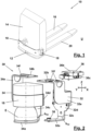
- an industrial truck is denoted generally by 10 .
- the industrial truck 10 can, for example, be a driverless industrial truck, also known as an AGV (automated guided vehicle). It includes a frame 12 to which a housing 14 is attached. In the housing 14 are all for operation components required for industrial truck 10, in particular a drive that enables industrial truck 10 to move on a surface U, a drive that enables lifting and lowering of lifting forks 16, the batteries required to power the drives, a control unit for controlling the drives, and sensors, for example Scanning devices 18 for detecting the surroundings of the industrial truck 10 and the like.
- the lifting forks 16 cover the wheel arms 20 of the truck 10, which are also connected to the frame 12 of the truck 10.
- each of the scanning devices 18 is assigned an adjustable suspension 30 .
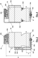
- This adjustable suspension 30 is described below with reference to FIG Figures 2 to 5 be explained in more detail.
- the adjustable suspension 30 comprises a first bracket 32, by means of which the suspension 30 can be fastened to the frame 12 of the industrial truck, a second bracket 34, by means of which the suspension 30 can be fastened to the scanning device 18, and an adjustment device 36, by means of which the first bracket 32 relative to the second bracket 34 can be adjusted.
- the first holder 32 has a lower section 32a which runs essentially horizontally and to which an elastically deformable bearing element 38 made of rubber, for example, is fastened.
- the second bracket 34 has a substantially horizontal lower section 34a, via which it is also connected to the bearing element 38 (see FIG Figures 3 and 4 ). In this way, the two holders 32 and 34 can be pivoted about two axes A and B running orthogonally to one another.
- the first bracket 32 also has a substantially horizontally running upper section 32b
- the second bracket 34 also has a substantially horizontally running upper section 34b, between which the adjusting arrangement 36 is arranged.
- the scanning plane E is arranged directly above the two lower sections 32a and 34a, namely at a distance h from them, the translational adjustment movement of the adjustment device 36 can be effectively converted into a pivoting movement of the Scanning device 18 are stocky.
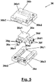
- the adjustment device 36 also has a structure that enables a very sensitive and reliably reproducible translatory adjustment movement.
- the adjusting device 36 includes a sliding element 36a, which is connected to an upper section 36a1 in a guide 36b1 of an upper link element 36b is guided in a translationally displaceable manner and is guided in a translationally displaceable manner with a lower section 36a2 in a guide 36c1 of a lower link element 36c.
- Adjusting device 36 also includes an upper adjusting screw 36d, which is rotatably mounted in upper link element 36b and is in threaded engagement with sliding element 36a, and a lower adjusting screw 36e, which is rotatably mounted in lower link element 36c and is in threaded engagement with sliding element 36a.
- the head 36d1 or 36e1 of the two adjusting screws 36d, 36e is accommodated in a pocket 36b2 or 36c2 of the link elements 36b and 36c in an axially fixed but rotatable manner.
- the two adjusting screws 36d and 36e are formed with a fine thread, i.e. a thread which can have a pitch of less than 1 mm. Since rotation of the set screws 36d and 36e by 1/8 turn can be easily reproduced, the set screws 36d and 36e enable adjustment with a fineness on the order of 0.1 mm. Together with the reduction factor h/H, pivoting movements around the axes A and B with a sensitivity of the order of 0.1° can therefore easily be achieved.
- lock screws 36f and 36g which pass through the longitudinal slots 36b3 and 36c3 of the link elements 36b and 36c.
- the first bracket 32 in the illustrated embodiment has three substantially vertical selling portions.
- a section 32c adjoining the lower section 32a is arranged at the level of and adjacent to the scanning plane E and has a width b 32 which is completely can be placed within the blind spot of the scanning device 18.
- the section 32c is followed above by a fastening section 32d, by means of which the first holder 32 can be fastened to the frame 12 of the industrial truck 10, for example by means of screws.
- a connection section 32e is also provided, which extends laterally from the attachment section 32d and is essentially L-shaped.
- the second bracket 34 also has three substantially vertical selling sections for connecting its lower section 34a to its upper section 34b.
- a section 34c adjoining the lower section 34a is arranged at the level of and adjacent to the scanning plane E and has a width b 34 which can be arranged completely within the blind spot of the scanning device 18 .
- the section 34c is followed above by a fastening section 34d, by means of which the second holder 34 can be fastened to the scanning device 18, for example by means of screws.
- a connection section 34e is also provided, which extends laterally from the attachment section 34d and is essentially L-shaped.
- Both the two sections 32c and 34c arranged at the level of the scanning plane E and the two fastening sections 32d and 34d are arranged essentially aligned with one another in the radial direction (see in particular figure 3 ).
- the two connecting sections 32e and 34e adjoin the fastening sections 32d and 34d on the opposite sides of the latter. Due to this configuration and the L-shape of the connecting sections 32e and 34e, on the back of the scanning device 18, on which both the sections 32c and 34c arranged at the level of the scanning plane E and the fastening sections 32d and 34d run, above the fastening sections 32d and 34d a Area of the scanning device 18 covered by any of the portions of the brackets 32 and 34. This makes it possible here for lines, for example at least one power supply line and/or at least one data line, to be able to be routed to or from the scanning device 18 .
- a corresponding connection is in figure 3 labeled 40.
- the holders 32 and 34 can each have at least one recess 32f or 34f, via the position and/or size and/or shape of which the elasticity of the holders 32 and 34 can be influenced.
Landscapes
- Engineering & Computer Science (AREA)
- General Engineering & Computer Science (AREA)
- Computer Networks & Wireless Communication (AREA)
- Physics & Mathematics (AREA)
- General Physics & Mathematics (AREA)
- Radar, Positioning & Navigation (AREA)
- Remote Sensing (AREA)
- Mechanical Engineering (AREA)
- Vehicle Body Suspensions (AREA)
Applications Claiming Priority (1)
| Application Number | Priority Date | Filing Date | Title |
|---|---|---|---|
| DE102021121220.0A DE102021121220A1 (de) | 2021-08-16 | 2021-08-16 | Verstellbare Aufhängung für eine Scanvorrichtung eines Flurförderzeugs und Kombination einer derartigen Aufhängung mit einer Scanvorrichtung eines Flurförderzeugs |
Publications (1)
| Publication Number | Publication Date |
|---|---|
| EP4137843A1 true EP4137843A1 (fr) | 2023-02-22 |
Family
ID=82786468
Family Applications (1)
| Application Number | Title | Priority Date | Filing Date |
|---|---|---|---|
| EP22188525.4A Pending EP4137843A1 (fr) | 2021-08-16 | 2022-08-03 | Suspension réglable pour un dispositif balayeur d'un chariot de manutention et combinaison d'une telle suspension avec un dispositif de balayage d'un chariot de manutention |
Country Status (2)
| Country | Link |
|---|---|
| EP (1) | EP4137843A1 (fr) |
| DE (1) | DE102021121220A1 (fr) |
Cited By (2)
| Publication number | Priority date | Publication date | Assignee | Title |
|---|---|---|---|---|
| CN116817126A (zh) * | 2023-03-07 | 2023-09-29 | 南昌工程学院 | 一种用于灰库灰位雷达扫描的两自由度位姿调整装置 |
| EP4431981A1 (fr) * | 2023-03-17 | 2024-09-18 | Sick Ag | Capteur orienté |
Citations (6)
| Publication number | Priority date | Publication date | Assignee | Title |
|---|---|---|---|---|
| DE4220634A1 (de) * | 1992-06-24 | 1994-01-05 | Deutsche Aerospace | Justiervorrichtung |
| DE19902287A1 (de) | 1999-01-21 | 2000-07-27 | Volkswagen Ag | Verfahren und Vorrichtung zur automatischen Justage eines Laserscanner-Sensors |
| DE102015208332A1 (de) * | 2015-05-06 | 2016-11-10 | Robert Bosch Gmbh | Mechanisch justierbarer Sensor sowie fahrzeugfeste Struktur |
| CN205709705U (zh) | 2016-04-18 | 2016-11-23 | 广州飞锐机器人科技有限公司 | 一种带有可调激光扫描仪的叉车 |
| CN206989905U (zh) | 2017-05-09 | 2018-02-09 | 河南科技大学 | 一种能够调整激光束与水平面夹角的激光扫描仪 |
| DE202018102171U1 (de) * | 2018-04-19 | 2019-07-22 | Kuka Deutschland Gmbh | Sensorhalter und Vorrichtung mit einem solchen Sensorhalter |
Family Cites Families (3)
| Publication number | Priority date | Publication date | Assignee | Title |
|---|---|---|---|---|
| DE9100510U1 (de) | 1991-01-17 | 1992-05-21 | Hinkel, Ralf, Dr., 67731 Otterbach | Winkelrichtlatte |
| DE10123166A1 (de) | 2001-03-31 | 2002-10-10 | Leica Microsystems | Stativ. insbesondere für ein Operationsmikroskop |
| US7992310B2 (en) | 2008-08-13 | 2011-08-09 | Trimble Navigation Limited | Reference beam generator and method |
-
2021
- 2021-08-16 DE DE102021121220.0A patent/DE102021121220A1/de active Pending
-
2022
- 2022-08-03 EP EP22188525.4A patent/EP4137843A1/fr active Pending
Patent Citations (6)
| Publication number | Priority date | Publication date | Assignee | Title |
|---|---|---|---|---|
| DE4220634A1 (de) * | 1992-06-24 | 1994-01-05 | Deutsche Aerospace | Justiervorrichtung |
| DE19902287A1 (de) | 1999-01-21 | 2000-07-27 | Volkswagen Ag | Verfahren und Vorrichtung zur automatischen Justage eines Laserscanner-Sensors |
| DE102015208332A1 (de) * | 2015-05-06 | 2016-11-10 | Robert Bosch Gmbh | Mechanisch justierbarer Sensor sowie fahrzeugfeste Struktur |
| CN205709705U (zh) | 2016-04-18 | 2016-11-23 | 广州飞锐机器人科技有限公司 | 一种带有可调激光扫描仪的叉车 |
| CN206989905U (zh) | 2017-05-09 | 2018-02-09 | 河南科技大学 | 一种能够调整激光束与水平面夹角的激光扫描仪 |
| DE202018102171U1 (de) * | 2018-04-19 | 2019-07-22 | Kuka Deutschland Gmbh | Sensorhalter und Vorrichtung mit einem solchen Sensorhalter |
Cited By (2)
| Publication number | Priority date | Publication date | Assignee | Title |
|---|---|---|---|---|
| CN116817126A (zh) * | 2023-03-07 | 2023-09-29 | 南昌工程学院 | 一种用于灰库灰位雷达扫描的两自由度位姿调整装置 |
| EP4431981A1 (fr) * | 2023-03-17 | 2024-09-18 | Sick Ag | Capteur orienté |
Also Published As
| Publication number | Publication date |
|---|---|
| DE102021121220A1 (de) | 2023-02-16 |
Similar Documents
| Publication | Publication Date | Title |
|---|---|---|
| DE69833044T2 (de) | Handbetriebene koordinatenpositioneniermaschine mit gegengewicht | |
| EP0684155A1 (fr) | Rétroviseur intérieur pour véhicules | |
| EP4137843A1 (fr) | Suspension réglable pour un dispositif balayeur d'un chariot de manutention et combinaison d'une telle suspension avec un dispositif de balayage d'un chariot de manutention | |
| WO1999013525A1 (fr) | Dispositif de fixation d'un capteur de distance sur un vehicule automobile | |
| EP4178816B1 (fr) | Composant de châssis doté d'une partie interne de joint | |
| EP2848357A1 (fr) | Dispositif pour porter le panneau de contrôle d'une machine-outil | |
| DE2106671A1 (de) | Vorrichtung zum Scharfen von Bohrern, insbesondere von Spiralbohrern | |
| DE19934197A1 (de) | Automatische Justiervorrichtung für einen an einem Fahrzeug angebrachten Sensor | |
| DE60308364T2 (de) | Vorrichtung zur Seiteneinstellung eines Fensterhebers für Kraftfahrzeuge | |
| DE3540766A1 (de) | Justierbares tuer- oder fensterband | |
| DE102017006061A1 (de) | Montagevorrichtung zur Montage eines Querlenkers eines Fahrzeugs | |
| DE19924056A1 (de) | Halterung für ein justierbares Gehäuse | |
| EP4354093B1 (fr) | Dispositif de fixation pour un capteur et unité de détection | |
| DE10154079A1 (de) | Halterung für ein justierbares Gehäuse | |
| DE69612080T2 (de) | Nivellieraufhängungsvorrichtung für eine Lastkraftwagen-Kabine | |
| EP3856113B1 (fr) | Colonne de table destinée à une table d'opération comprenant un mécanisme de renforcement destiné à un guidage cylindrique | |
| WO2011045366A1 (fr) | Dispositif pour fixer un cadre de support | |
| DE8807681U1 (de) | Radiusbetätiger für einen Sicherheitsschalter | |
| EP0603496A1 (fr) | Guide à galets et dispositif de coulissement | |
| EP0267373B1 (fr) | Support pour un rétroviseur extérieur d'un véhicule à moteur | |
| EP1308379B1 (fr) | Support pivotable et réglable en direction longitudinal pour une partie pivotable de carrosserie, en particulier capot de coffre à bagages | |
| DE19909283A1 (de) | Verfahren zur Befestigung von Sitzschienen | |
| DE112021003198T5 (de) | Spritzgussmaschine | |
| DE102016114548A1 (de) | Befestigung eines laborgerätes | |
| EP4219277B1 (fr) | Système de montage de cabine et montage de cabine |
Legal Events
| Date | Code | Title | Description |
|---|---|---|---|
| PUAI | Public reference made under article 153(3) epc to a published international application that has entered the european phase |
Free format text: ORIGINAL CODE: 0009012 |
|
| STAA | Information on the status of an ep patent application or granted ep patent |
Free format text: STATUS: THE APPLICATION HAS BEEN PUBLISHED |
|
| AK | Designated contracting states |
Kind code of ref document: A1 Designated state(s): AL AT BE BG CH CY CZ DE DK EE ES FI FR GB GR HR HU IE IS IT LI LT LU LV MC MK MT NL NO PL PT RO RS SE SI SK SM TR |
|
| STAA | Information on the status of an ep patent application or granted ep patent |
Free format text: STATUS: REQUEST FOR EXAMINATION WAS MADE |
|
| P01 | Opt-out of the competence of the unified patent court (upc) registered |
Effective date: 20230628 |
|
| 17P | Request for examination filed |
Effective date: 20230707 |
|
| RBV | Designated contracting states (corrected) |
Designated state(s): AL AT BE BG CH CY CZ DE DK EE ES FI FR GB GR HR HU IE IS IT LI LT LU LV MC MK MT NL NO PL PT RO RS SE SI SK SM TR |
|
| STAA | Information on the status of an ep patent application or granted ep patent |
Free format text: STATUS: EXAMINATION IS IN PROGRESS |
|
| 17Q | First examination report despatched |
Effective date: 20250708 |