EP1308548B1 - Machine à coudre et à broder - Google Patents
Machine à coudre et à broder Download PDFInfo
- Publication number
- EP1308548B1 EP1308548B1 EP02405816A EP02405816A EP1308548B1 EP 1308548 B1 EP1308548 B1 EP 1308548B1 EP 02405816 A EP02405816 A EP 02405816A EP 02405816 A EP02405816 A EP 02405816A EP 1308548 B1 EP1308548 B1 EP 1308548B1
- Authority
- EP
- European Patent Office
- Prior art keywords
- embroidery frame
- embroidery
- drive unit
- impulse
- sewing
- Prior art date
- Legal status (The legal status is an assumption and is not a legal conclusion. Google has not performed a legal analysis and makes no representation as to the accuracy of the status listed.)
- Expired - Lifetime
Links
Images

Classifications
-
- D—TEXTILES; PAPER
- D05—SEWING; EMBROIDERING; TUFTING
- D05B—SEWING
- D05B19/00—Program-controlled sewing machines
- D05B19/02—Sewing machines having electronic memory or microprocessor control unit
- D05B19/12—Sewing machines having electronic memory or microprocessor control unit characterised by control of operation of machine
- D05B19/16—Control of workpiece movement, e.g. modulation of travel of feed dog
-
- D—TEXTILES; PAPER
- D05—SEWING; EMBROIDERING; TUFTING
- D05B—SEWING
- D05B39/00—Workpiece carriers
Definitions
- the invention relates to a sewing or embroidery machine according to the preamble of patent claim 1.
- the embroidering of a material, which is clamped in an embroidery frame and driven by a drive unit in the X and Y directions, is known.
- the drive unit is often part of the forearm; in household sewing machines, the drive units, also called embroidery modules, are docked to the sewing machine, ie to the forearm and / or the base plate and held there free of play.
- the connection between the embroidery frame and the drive unit is made by an embroidery frame carrier, which is connected to the drive elements in the drive unit, and holding and locking devices on the hoop.
- the pulse-generating switching means in DE 29612102 U 1 also serve to visually indicate via the display on a display device (display) on the sewing machine of the seamstress which embroidery frame (eg round, oval, square, etc.) is docked and also, at which docking on the hoop this is done.
- a display device display
- the seamstress is also put into the picture, which sewing area within the embroidery frame can now be embroidered.
- the display also shows the pattern to be embroidered in the sewing area.
- Object of the present invention is therefore to provide a sewing or embroidery machine with a drive unit for a hoop, with which drive unit not only the type and size of the hoop and the docking position on the hoop, but also the exact actual position of the hoop with respect to the drive unit and so that the needle position can be determined.
- the arrangement of one or more reference points on the embroidery frame makes it possible, on the one hand, to determine the exact position of the Determine hoop relative to the reference zero point on the drive unit and on the other hand also determine whether the embroidery hoop is correctly connected to the embroidery frame carrier or determine whether an embroidery frame is docked on the embroidery frame carrier.
- a correction can be automatically made with the machine control or the start of embroidering can be prevented. This makes it possible to guide and create embroidery motifs over an area extending beyond the embroidery area without the attachment and follow-up points to the previously embroidered areas being visible after the embroidery frame has been moved.
- the sewing machine according to Figure 1 includes the usual, sometimes unspecified sewing organs, controls and other equipment. It consists essentially of the sewing machine housing 1, the free arm 3 and the base plate 5. On the machine housing 1 are a screen 7 (display), a trackball 9 with associated actuator button 11 and delete button 13 and a row of keys 15 for the direct selection of unspecified special functions arranged. An opening 17 is used to hold external storage means, such as program cards for embroidery designs. Including the main switch 19, the connector 21 for the power supply and the socket 23 are arranged for the connection of a foot starter, not shown. The cooperating through the tap hole 25 with a not shown gripper device needle is denoted by 27, while the non-illustrated embroidery material holding down presser foot is denoted by 29.
- the base unit 31 of an embroidery module 33 connectable to the sewing machine by non-illustrated mechanical and electrical connection means includes program controlled drive means (eg, linear motors) for an embroidery frame carrier 35 in an embroidery frame drive unit 36 for driving the latter with the embroidery frame 37 attached thereto in the X direction.
- program controlled drive means eg, linear motors
- the drive means for driving the embroidery frame 37 are accommodated in the Y direction.
- the Embroidery frame 37 is connected via at least one releasable holding device 39 with the arranged in the embroidery frame carrier 35, not visible drive means. The structure of the holding device 39 will not be explained in detail.
- differently sized or differently shaped embroidery frames 37 can be connected to the embroidery module 33.
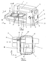
- the rectangular embroidery frame 37 shown in Figure 1 has only one holding device 39 on a narrow side; In the plan view according to FIG. 2, another longer embroidery frame 37 with two holding devices 39 spaced apart on one longitudinal side can be seen.
- FIG. 3 shows a detail of an even longer embroidery frame 37 with three holding devices 39.
- Each embroidery frame 37 comprises at least one tensioning device 41, with which a material can be clamped.
- Each holding device 39 comprises in the illustrated examples one or more control cams or prongs 43 and additionally each a reference cam or prongs 44.
- the latter have a relation to the embroidery frame 37 exactly predetermined position. Together with the exact known position of the drive unit 36 can with the reference cam 44, the actual position of the hoop 37 with the target position and, if deviations are detected, a correction is made.
- the position of the embroidery frame 37 can be corrected if, for example, steps of a stepping motor serving as a drive have been lost.
- a correction of the position of the embroidery frame 37 is of course not performed if the reference cam 44 can not be detected because the embroidery frame 37 is not or incompletely docked to the holding device 39.
- the reference cam 44 thus has several functions that ensure proper operation: It determines whether the actual position of the hoop 37 coincides with the target position and allows for correction. It further ensures proper attachment to the fixture 39 and stops the sewing machine if any of the parameters are out of order.
- a proximity sensor or other element are fixedly mounted on the embroidery frame carrier 35, with an identification of the control cam 43 and the reference cam 44 in a relative movement between the Embroidery frame 37 and the embroidery module 33 or scanned when docking.
- the number, the location and / or the geometric shape of the control cam 43 are the basis for recognizing the Embroidery frame position, the size and shape and the docking position of the hoop 37.
- the reference cam 44 is the exact and proper positioning of the hoop 37 with respect to the embroidery module 33rd
- the operation is explained in more detail below.
- the operator / seamstress looks for the suitable for the embroidery designs to be created hoop 37, clamped therein with the jig 41, the fabric in the form of a textile structure and then docks the hoop 37 to the embroidery module 33 at.
- the embroidery module 33 then passes the embroidery frame 37 in the Y direction past the impulse-giving button 45. This detects the control cam 43, the data of the docked embroidery frame 37 and the docking position, if the embroidery frame 37 has a plurality of docking positions.
- the exact position of the hoop 37 with respect to the drive unit 36 is ensured by the reference cam 44. At the same time the perfect attachment is checked.
- the sewing machine is prevented from starting the embroidering operation. If a difference between the actual and the nominal position is determined, then a correction takes place, ie the embroidery frame 37 is initially guided to the correct desired position before embroidering begins.
- a precisely defined reference point ie one with respect to the needle 27 exactly Defined position on the embroidery module 33. The checking of the target / actual position can be repeated during embroidering periodically or each time the reference cam 44 passes the button 45.
- the identification and adjusting means according to the invention also enable pattern-true embroidering of a sewing material in an embroidery frame 37 whose embroidery field is greater than the working range of the sewing machine. Consequently, the patterns overlapping the work area of the sewing machine can be completed in regions, and the adjacent areas can be seamlessly continued after the embroidery frame 37 has been adjusted.
- a complex division of the embroidery patterns into coherent individual patterns as proposed in US Pat. No. 6,237,516 B1, is not necessary.
- the first piercing location of the needle 27 after an embroidery frame displacement is calculated exactly by the machine control. The operator therefore has no adjustment to make, as proposed for example in US 5,865,133.
Landscapes
- Engineering & Computer Science (AREA)
- Textile Engineering (AREA)
- Computer Hardware Design (AREA)
- Microelectronics & Electronic Packaging (AREA)
- Sewing Machines And Sewing (AREA)
Claims (3)
- Machine à coudre ou à broder comprenant un module de broderie (33) doté d'une unité de commande pour cadre à broder (36) destinée à entraîner des cadres à broder (37) remplaçables de différentes tailles dans les directions X et Y, un support de cadre à broder (35) sur l'unité d'entraînement pour cadre à broder (36) pour assembler de façon amovible le cadre à broder (37) et l'unité d'entraînement (36), ainsi qu'un cadre à broder (37) équipé d'un dispositif de fixation et de verrouillage pour cadre à broder (39) pour réaliser un assemblage sans jeu entre l'unité d'entraînement (36) et le cadre à broder (37), comprenant également des moyens déclenchant des impulsions (43) sur le cadre à broder (37) et des moyens de commutation générant des impulsions (45) sur l'unité d'entraînement (36) pour identifier le cadre à broder (37) installé, caractérisée en ce qu'à chaque moyen déclenchant des impulsions (43) est associé un élément de référence (44) sur le cadre à broder (37), lequel élément de référence peut être identifié et lu par un palpeur fixe (45) fixé sur l'unité d'entraînement (36) en tant que moyen de commutation et permet de comparer la position de référence réelle relevée par le palpeur (45) situé sur l'élément de référence (44) à la position de consigne du cadre à broder (37) par rapport au dispositif de fixation (39).
- Machine à coudre et à broder selon la revendication 1, caractérisée en ce que l'élément de référence déclenchant des impulsions en vue de déterminer la position de référence comprend au moins une came de référence (44) dont la position géométrique sur le cadre à broder (37) est définie exactement.
- Machine à coudre et à broder selon la revendication 1 ou 2, caractérisée en ce que la position réelle du cadre à broder (37) par rapport à l'unité d'entraînement (36) peut être vérifiée à chaque passage des éléments de référence déclenchant des impulsions (43, 44) devant le moyen de commutation générant des impulsions (45) et corrigée par la commande de la machine.
Applications Claiming Priority (2)
| Application Number | Priority Date | Filing Date | Title |
|---|---|---|---|
| CH20132001 | 2001-11-02 | ||
| CH20132001 | 2001-11-02 |
Publications (3)
| Publication Number | Publication Date |
|---|---|
| EP1308548A2 EP1308548A2 (fr) | 2003-05-07 |
| EP1308548A3 EP1308548A3 (fr) | 2004-11-24 |
| EP1308548B1 true EP1308548B1 (fr) | 2006-03-22 |
Family
ID=4567131
Family Applications (1)
| Application Number | Title | Priority Date | Filing Date |
|---|---|---|---|
| EP02405816A Expired - Lifetime EP1308548B1 (fr) | 2001-11-02 | 2002-09-23 | Machine à coudre et à broder |
Country Status (4)
| Country | Link |
|---|---|
| US (1) | US6568337B1 (fr) |
| EP (1) | EP1308548B1 (fr) |
| AT (1) | ATE321163T1 (fr) |
| DE (1) | DE50206136D1 (fr) |
Families Citing this family (9)
| Publication number | Priority date | Publication date | Assignee | Title |
|---|---|---|---|---|
| JP3815565B2 (ja) * | 2003-02-27 | 2006-08-30 | ブラザー工業株式会社 | 刺繍ミシン |
| WO2004106611A1 (fr) * | 2003-05-29 | 2004-12-09 | Aisin Seiki Kabushiki Kaisha | Systeme de broderie et de teinture |
| EP1738007B1 (fr) * | 2003-12-15 | 2012-09-19 | BERNINA International AG | Procede et dispositif pour commander le mouvement de l'aiguille d'une machine a coudre |
| DE502006000556D1 (de) * | 2005-06-21 | 2008-05-15 | Bernina Int Ag | Verfahren und Vorrichtung zur Minimierung von Einstichfehlern bei Stickvorrichtungen |
| DE502006000763D1 (de) * | 2005-11-07 | 2008-06-26 | Bernina Int Ag | Stickmodul für eine Freiarm-Nähmaschine |
| JP2007244463A (ja) * | 2006-03-14 | 2007-09-27 | Brother Ind Ltd | ミシンの布保持枠移送装置 |
| JP4974044B2 (ja) * | 2006-03-23 | 2012-07-11 | ブラザー工業株式会社 | 刺繍縫製可能なミシン |
| JP2008307159A (ja) * | 2007-06-13 | 2008-12-25 | Brother Ind Ltd | 刺繍縫製可能なミシン |
| JP5141299B2 (ja) * | 2008-02-28 | 2013-02-13 | ブラザー工業株式会社 | ミシン |
Family Cites Families (5)
| Publication number | Priority date | Publication date | Assignee | Title |
|---|---|---|---|---|
| JPS6035458B2 (ja) | 1980-08-02 | 1985-08-14 | アイシン精機株式会社 | 刺しゆう枠 |
| DE29612102U1 (de) * | 1996-07-11 | 1996-09-12 | Fritz Gegauf AG Bernina-Nähmaschinenfabrik, Steckborn, Thurgau | Vorrichtung zum automatischen Identifizieren eines Stickrahmens an einer Näh- oder Stickmaschine |
| DE29614512U1 (de) | 1996-08-21 | 1996-10-02 | Fritz Gegauf AG Bernina-Nähmaschinenfabrik, Steckborn, Thurgau | Vorrichtung zum lösbaren Befestigen eines Stickrahmens |
| EP0860533A3 (fr) * | 1997-02-25 | 1999-04-07 | G.M. Pfaff Aktiengesellschaft | Procédé pour broder des motifs surdimensionnés |
| JP4239319B2 (ja) * | 1999-09-30 | 2009-03-18 | ブラザー工業株式会社 | ミシン |
-
2002
- 2002-09-23 AT AT02405816T patent/ATE321163T1/de not_active IP Right Cessation
- 2002-09-23 EP EP02405816A patent/EP1308548B1/fr not_active Expired - Lifetime
- 2002-09-23 DE DE50206136T patent/DE50206136D1/de not_active Expired - Lifetime
- 2002-10-31 US US10/284,712 patent/US6568337B1/en not_active Expired - Fee Related
Also Published As
| Publication number | Publication date |
|---|---|
| DE50206136D1 (de) | 2006-05-11 |
| US6568337B1 (en) | 2003-05-27 |
| ATE321163T1 (de) | 2006-04-15 |
| EP1308548A2 (fr) | 2003-05-07 |
| US20030084831A1 (en) | 2003-05-08 |
| EP1308548A3 (fr) | 2004-11-24 |
Similar Documents
| Publication | Publication Date | Title |
|---|---|---|
| US5505150A (en) | Method and apparatus for facilitating loop take time adjustment in multi-needle quilting machine | |
| EP2172585B1 (fr) | Dispositif et procédé de découpage de structures plates textiles et non textiles | |
| DE69131534T2 (de) | Stickmaschine | |
| EP1308548B1 (fr) | Machine à coudre et à broder | |
| DE102007056132A1 (de) | Nähmaschine | |
| DE2160093A1 (de) | Vorrichtung zur automatischen Führung von flachem, blattförmigem Material | |
| EP0860533A2 (fr) | Procédé pour broder des motifs surdimensionnés | |
| CH706492A1 (de) | Vorrichtung und Verfahren zum Stanzen eines Flächengebildes mit einer Nähmaschine. | |
| DE3216528C2 (de) | Nähautomat mit einer Einrichtung zur Identifizierung von Art und/oder Größe eines eingesetzten Nähgut-Halters | |
| EP0877112B1 (fr) | Procédé et dispositif pour broder des ouvrages tubulaires | |
| US5101746A (en) | Work holder for sewing machines | |
| DE7605072U1 (de) | Naehaggregat zum bilden von formnaehten | |
| DE2500471A1 (de) | Naehmaschine mit musterwaehlsystem | |
| DE19851084C2 (de) | Antriebsmechanismus für eine Nähmaschine | |
| DE19714520C2 (de) | Nähmaschine | |
| DE4214092A1 (de) | Naehmaschine, geeignet zur bildung von knopfloechern, und verfahren zur bildung von knopfloechern | |
| DE3527454A1 (de) | Vorrichtung zur steuerung einer bewegung fuer eine naehmaschine | |
| DE8114009U1 (de) | "zusatzvorrichtung fuer eine knopfannaehmaschine" | |
| EP1270788A1 (fr) | Dispositif pour attacher de manière amovible un cadre à broder à un support de cadre à broder | |
| DE10112474C1 (de) | Verfahren zum Annähen von Beilege-Teilen an ein Nähgutteil und Näh-Arbeitsplatz zur Durchführung des Verfahrens | |
| DE10242450B4 (de) | Rundstrickmaschine und eine automatisch laufende Einrichtung zur Mustereinstellung in einer Rundstrickmaschine | |
| DE3619345A1 (de) | Automatischer groessen-austausch bei einem naehautomaten | |
| DE3235576A1 (de) | Verfahren zur identifizierung eines naehgut-halters und naehautomat zur durchfuehrung des verfahrens | |
| EP4060106B1 (fr) | Machine à coudre | |
| DE19712421C1 (de) | Verfahren und Vorrichtung zur genauen Bestimmung des Nadel-Nullpunktes der Nähmaschine eines Nähautomaten |
Legal Events
| Date | Code | Title | Description |
|---|---|---|---|
| PUAI | Public reference made under article 153(3) epc to a published international application that has entered the european phase |
Free format text: ORIGINAL CODE: 0009012 |
|
| AK | Designated contracting states |
Designated state(s): AT BE BG CH CY CZ DE DK EE ES FI FR GB GR IE IT LI LU MC NL PT SE SK TR |
|
| AX | Request for extension of the european patent |
Extension state: AL LT LV MK RO SI |
|
| PUAL | Search report despatched |
Free format text: ORIGINAL CODE: 0009013 |
|
| AK | Designated contracting states |
Kind code of ref document: A3 Designated state(s): AT BE BG CH CY CZ DE DK EE ES FI FR GB GR IE IT LI LU MC NL PT SE SK TR |
|
| AX | Request for extension of the european patent |
Extension state: AL LT LV MK RO SI |
|
| 17P | Request for examination filed |
Effective date: 20050117 |
|
| GRAP | Despatch of communication of intention to grant a patent |
Free format text: ORIGINAL CODE: EPIDOSNIGR1 |
|
| AKX | Designation fees paid |
Designated state(s): AT BE BG CH CY CZ DE DK EE ES FI FR GB GR IE IT LI LU MC NL PT SE SK TR |
|
| GRAS | Grant fee paid |
Free format text: ORIGINAL CODE: EPIDOSNIGR3 |
|
| GRAA | (expected) grant |
Free format text: ORIGINAL CODE: 0009210 |
|
| AK | Designated contracting states |
Kind code of ref document: B1 Designated state(s): AT BE BG CH CY CZ DE DK EE ES FI FR GB GR IE IT LI LU MC NL PT SE SK TR |
|
| PG25 | Lapsed in a contracting state [announced via postgrant information from national office to epo] |
Ref country code: IT Free format text: LAPSE BECAUSE OF FAILURE TO SUBMIT A TRANSLATION OF THE DESCRIPTION OR TO PAY THE FEE WITHIN THE PRESCRIBED TIME-LIMIT;WARNING: LAPSES OF ITALIAN PATENTS WITH EFFECTIVE DATE BEFORE 2007 MAY HAVE OCCURRED AT ANY TIME BEFORE 2007. THE CORRECT EFFECTIVE DATE MAY BE DIFFERENT FROM THE ONE RECORDED. Effective date: 20060322 Ref country code: IE Free format text: LAPSE BECAUSE OF FAILURE TO SUBMIT A TRANSLATION OF THE DESCRIPTION OR TO PAY THE FEE WITHIN THE PRESCRIBED TIME-LIMIT Effective date: 20060322 Ref country code: NL Free format text: LAPSE BECAUSE OF FAILURE TO SUBMIT A TRANSLATION OF THE DESCRIPTION OR TO PAY THE FEE WITHIN THE PRESCRIBED TIME-LIMIT Effective date: 20060322 Ref country code: SK Free format text: LAPSE BECAUSE OF FAILURE TO SUBMIT A TRANSLATION OF THE DESCRIPTION OR TO PAY THE FEE WITHIN THE PRESCRIBED TIME-LIMIT Effective date: 20060322 |
|
| REG | Reference to a national code |
Ref country code: GB Ref legal event code: FG4D Free format text: NOT ENGLISH |
|
| REG | Reference to a national code |
Ref country code: CH Ref legal event code: EP Ref country code: CH Ref legal event code: NV Representative=s name: HANS RUDOLF GACHNANG PATENTANWALT |
|
| REG | Reference to a national code |
Ref country code: IE Ref legal event code: FG4D Free format text: LANGUAGE OF EP DOCUMENT: GERMAN |
|
| REF | Corresponds to: |
Ref document number: 50206136 Country of ref document: DE Date of ref document: 20060511 Kind code of ref document: P |
|
| PG25 | Lapsed in a contracting state [announced via postgrant information from national office to epo] |
Ref country code: BG Free format text: LAPSE BECAUSE OF FAILURE TO SUBMIT A TRANSLATION OF THE DESCRIPTION OR TO PAY THE FEE WITHIN THE PRESCRIBED TIME-LIMIT Effective date: 20060622 Ref country code: DK Free format text: LAPSE BECAUSE OF FAILURE TO SUBMIT A TRANSLATION OF THE DESCRIPTION OR TO PAY THE FEE WITHIN THE PRESCRIBED TIME-LIMIT Effective date: 20060622 |
|
| PG25 | Lapsed in a contracting state [announced via postgrant information from national office to epo] |
Ref country code: ES Free format text: LAPSE BECAUSE OF FAILURE TO SUBMIT A TRANSLATION OF THE DESCRIPTION OR TO PAY THE FEE WITHIN THE PRESCRIBED TIME-LIMIT Effective date: 20060703 |
|
| REG | Reference to a national code |
Ref country code: SE Ref legal event code: TRGR |
|
| GBT | Gb: translation of ep patent filed (gb section 77(6)(a)/1977) |
Effective date: 20060719 |
|
| PG25 | Lapsed in a contracting state [announced via postgrant information from national office to epo] |
Ref country code: PT Free format text: LAPSE BECAUSE OF FAILURE TO SUBMIT A TRANSLATION OF THE DESCRIPTION OR TO PAY THE FEE WITHIN THE PRESCRIBED TIME-LIMIT Effective date: 20060822 |
|
| NLV1 | Nl: lapsed or annulled due to failure to fulfill the requirements of art. 29p and 29m of the patents act | ||
| REG | Reference to a national code |
Ref country code: SE Ref legal event code: RPOT |
|
| PG25 | Lapsed in a contracting state [announced via postgrant information from national office to epo] |
Ref country code: MC Free format text: LAPSE BECAUSE OF NON-PAYMENT OF DUE FEES Effective date: 20060930 Ref country code: BE Free format text: LAPSE BECAUSE OF NON-PAYMENT OF DUE FEES Effective date: 20060930 |
|
| REG | Reference to a national code |
Ref country code: IE Ref legal event code: FD4D |
|
| PLBE | No opposition filed within time limit |
Free format text: ORIGINAL CODE: 0009261 |
|
| STAA | Information on the status of an ep patent application or granted ep patent |
Free format text: STATUS: NO OPPOSITION FILED WITHIN TIME LIMIT |
|
| 26N | No opposition filed |
Effective date: 20061227 |
|
| EN | Fr: translation not filed | ||
| PG25 | Lapsed in a contracting state [announced via postgrant information from national office to epo] |
Ref country code: AT Free format text: LAPSE BECAUSE OF NON-PAYMENT OF DUE FEES Effective date: 20060923 |
|
| BERE | Be: lapsed |
Owner name: FRITZ GEGAUF A.G. BERNINA-NAHMASCHINENFABRIK Effective date: 20060930 |
|
| PG25 | Lapsed in a contracting state [announced via postgrant information from national office to epo] |
Ref country code: FR Free format text: LAPSE BECAUSE OF FAILURE TO SUBMIT A TRANSLATION OF THE DESCRIPTION OR TO PAY THE FEE WITHIN THE PRESCRIBED TIME-LIMIT Effective date: 20070309 Ref country code: GR Free format text: LAPSE BECAUSE OF FAILURE TO SUBMIT A TRANSLATION OF THE DESCRIPTION OR TO PAY THE FEE WITHIN THE PRESCRIBED TIME-LIMIT Effective date: 20060623 |
|
| PG25 | Lapsed in a contracting state [announced via postgrant information from national office to epo] |
Ref country code: FI Free format text: LAPSE BECAUSE OF FAILURE TO SUBMIT A TRANSLATION OF THE DESCRIPTION OR TO PAY THE FEE WITHIN THE PRESCRIBED TIME-LIMIT Effective date: 20060322 Ref country code: EE Free format text: LAPSE BECAUSE OF FAILURE TO SUBMIT A TRANSLATION OF THE DESCRIPTION OR TO PAY THE FEE WITHIN THE PRESCRIBED TIME-LIMIT Effective date: 20060322 |
|
| PG25 | Lapsed in a contracting state [announced via postgrant information from national office to epo] |
Ref country code: LU Free format text: LAPSE BECAUSE OF NON-PAYMENT OF DUE FEES Effective date: 20060923 Ref country code: TR Free format text: LAPSE BECAUSE OF FAILURE TO SUBMIT A TRANSLATION OF THE DESCRIPTION OR TO PAY THE FEE WITHIN THE PRESCRIBED TIME-LIMIT Effective date: 20060322 |
|
| REG | Reference to a national code |
Ref country code: CH Ref legal event code: PFA Owner name: BERNINA INTERNATIONAL AG Free format text: FRITZ GEGAUF AG BERNINA-NAEHMASCHINENFABRIK#SEESTRASSE#8266 STECKBORN (CH) -TRANSFER TO- BERNINA INTERNATIONAL AG#SEESTRASSE 161#8266 STECKBORN (CH) |
|
| PG25 | Lapsed in a contracting state [announced via postgrant information from national office to epo] |
Ref country code: FR Free format text: LAPSE BECAUSE OF FAILURE TO SUBMIT A TRANSLATION OF THE DESCRIPTION OR TO PAY THE FEE WITHIN THE PRESCRIBED TIME-LIMIT Effective date: 20060322 Ref country code: CY Free format text: LAPSE BECAUSE OF FAILURE TO SUBMIT A TRANSLATION OF THE DESCRIPTION OR TO PAY THE FEE WITHIN THE PRESCRIBED TIME-LIMIT Effective date: 20060322 |
|
| PGFP | Annual fee paid to national office [announced via postgrant information from national office to epo] |
Ref country code: CZ Payment date: 20080918 Year of fee payment: 7 |
|
| PG25 | Lapsed in a contracting state [announced via postgrant information from national office to epo] |
Ref country code: CZ Free format text: LAPSE BECAUSE OF NON-PAYMENT OF DUE FEES Effective date: 20090923 |
|
| PGFP | Annual fee paid to national office [announced via postgrant information from national office to epo] |
Ref country code: CH Payment date: 20100910 Year of fee payment: 9 |
|
| PGFP | Annual fee paid to national office [announced via postgrant information from national office to epo] |
Ref country code: SE Payment date: 20100928 Year of fee payment: 9 |
|
| PGFP | Annual fee paid to national office [announced via postgrant information from national office to epo] |
Ref country code: GB Payment date: 20100820 Year of fee payment: 9 |
|
| PGFP | Annual fee paid to national office [announced via postgrant information from national office to epo] |
Ref country code: DE Payment date: 20100901 Year of fee payment: 9 |
|
| REG | Reference to a national code |
Ref country code: CH Ref legal event code: PL |
|
| GBPC | Gb: european patent ceased through non-payment of renewal fee |
Effective date: 20110923 |
|
| REG | Reference to a national code |
Ref country code: SE Ref legal event code: EUG |
|
| REG | Reference to a national code |
Ref country code: DE Ref legal event code: R119 Ref document number: 50206136 Country of ref document: DE Effective date: 20120403 |
|
| PG25 | Lapsed in a contracting state [announced via postgrant information from national office to epo] |
Ref country code: DE Free format text: LAPSE BECAUSE OF NON-PAYMENT OF DUE FEES Effective date: 20120403 Ref country code: LI Free format text: LAPSE BECAUSE OF NON-PAYMENT OF DUE FEES Effective date: 20110930 Ref country code: CH Free format text: LAPSE BECAUSE OF NON-PAYMENT OF DUE FEES Effective date: 20110930 |
|
| PG25 | Lapsed in a contracting state [announced via postgrant information from national office to epo] |
Ref country code: GB Free format text: LAPSE BECAUSE OF NON-PAYMENT OF DUE FEES Effective date: 20110923 |
|
| PG25 | Lapsed in a contracting state [announced via postgrant information from national office to epo] |
Ref country code: SE Free format text: LAPSE BECAUSE OF NON-PAYMENT OF DUE FEES Effective date: 20110924 |