EP1308549A2 - Rundbreithalter zum Behandeln textiler Schlauchware - Google Patents
Rundbreithalter zum Behandeln textiler Schlauchware Download PDFInfo
- Publication number
- EP1308549A2 EP1308549A2 EP02020625A EP02020625A EP1308549A2 EP 1308549 A2 EP1308549 A2 EP 1308549A2 EP 02020625 A EP02020625 A EP 02020625A EP 02020625 A EP02020625 A EP 02020625A EP 1308549 A2 EP1308549 A2 EP 1308549A2
- Authority
- EP
- European Patent Office
- Prior art keywords
- parts
- goods
- magnets
- circular spreader
- spreader according
- Prior art date
- Legal status (The legal status is an assumption and is not a legal conclusion. Google has not performed a legal analysis and makes no representation as to the accuracy of the status listed.)
- Granted
Links
Images

Classifications
-
- D—TEXTILES; PAPER
- D06—TREATMENT OF TEXTILES OR THE LIKE; LAUNDERING; FLEXIBLE MATERIALS NOT OTHERWISE PROVIDED FOR
- D06C—FINISHING, DRESSING, TENTERING OR STRETCHING TEXTILE FABRICS
- D06C5/00—Shaping or stretching of tubular fabrics upon cores or internal frames
Definitions
- the invention relates to a circular spreader for treating textile tubular goods the preamble of claim 1.
- Plants for treating e.g. Tubular knitted fabrics come with at least one so-called circular spreader held from the outside, which the tubular knitted fabric from the inside e.g. spread out triangular or almost round.
- the tubular knitted fabric is spread out in the form of appropriate guide elements of the spreader.
- a circular spreader known from DE 29 35 374 C2 has, in order to keep it in a floating position at a low surface pressure between an inlet part and a first support element supporting the spreader on the one hand and between an outlet part and a second support element supporting the spreader on the other of the central carrier each have a body tapering in the longitudinal direction as an inlet or outlet part. Both the inlet part and the outlet part are arranged a support element which is adapted to the shape of the tapering body and partially encompasses the body and which has outlet openings distributed around the circumference and opening into the intermediate space designed as a goods guide gap towards the inlet and outlet part for one Supporting fluid is equipped.
- the invention has for its object a circular spreader of the known type to further develop such that during the continuous flow of goods both in Inlet area as well as in the outlet area of the rotary spreader surface pressures are excluded and as a result the structure of the tubular goods is unaffected remains.
- both the at least one Tubular goods inlet part as well as the at least one tubular goods outlet part Parts equipped with magnets are a second part with magnets
- Tubular infeed part encompasses that forming a goods guide gap second part equipped with magnets
- the tubular goods outlet part under training encompasses a goods guide gap and the magnets of the tubular goods inlet and -Outlet part and the magnets of the tubular goods inlet and outlet part encompassing parts have the same polarity.
- the magnets equipped with the aforementioned parts can be permanent magnets or electromagnets in a further embodiment of the invention. It is conceivable that, for example, the inlet and outlet part is equipped with permanent magnets and the part encompassing the inlet and outlet part is equipped with electromagnets.
- the magnets of the individual parts can be an integral part of the parts or the individual parts can even be made of magnetic or magnetizable material exist or be designed as an electromagnet.
- the part encompassing the inlet and outlet part consists of at least a first approximately segment-like part of a ring and a second approximately segment-like part of a ring. Each ring part is then in operative connection with suitable adjusting means.
- the width of the goods guide gap can be adjustable, as already mentioned above.
- the change in the width of the goods guide gap requires that either the permanent magnets are strong enough or that the strength of the magnetic forces can be changed.
- This is achieved in a further embodiment of the invention in that at least the magnets of the parts encompassing the inlet and outlet parts are electromagnets, the field strength of which is variable.
- the Spread tubular knitted fabric in the treatment process be it through liquid or gaseous treatment agent in the area of the inlet and outlet of the rotary spreader in their structure is not affected.
- the circular spreader 1 has a frusto-conical inlet part 7 on the inlet side of the tubular fabric 2.
- the circular spreader 1 has an oval inlet part 7a on the inlet side of the tubular fabric 2.
- an outlet part 8 is connected to the central carrier 3.
- the outlet part 8 here consists, for example, of two interconnected frustoconical or oval bodies. Magnets of the same polarity are integrated in the frustoconical end piece 7 on the goods inlet side of the rotary spreader.
- the frustoconical end piece 7 is encompassed by at least a first and a second half-ring segment 10, see also FIG.
- the two half-ring segments 10 form parts equipped with magnets, which together create a conical passage as a counterpart to the frustoconical or oval end piece.
- the magnets of the assembled parts 10 are of the same polarity. Magnets of the same polarity are integrated in the inlet part 7 on the goods outlet side of the circular spreader.
- the inlet part 7 is radially encompassed by at least a first and a second semi-ring-like body 12 to form a goods guide gap 13, the inner contour of which is approximately a mirror image of the outer contour of the Outlet part 8 is formed.
- the body 12 is equipped with magnets of the same polarity.
- the two are half-ring-shaped body 12 via suitable means with one not here shown actuator connected.
Landscapes
- Engineering & Computer Science (AREA)
- Textile Engineering (AREA)
- Treatment Of Fiber Materials (AREA)
- Knitting Machines (AREA)
Abstract
Erfindungsgemäß wird die Aufgabe dadurch gelöst, dass sowohl das wenigstens eine Schlauchware-Einlaufteil (7) als auch das wenigstens eine Schlauchware-Auslaufteil (8) erste mit Magneten bestückte Teile sind, dass ein zweites mit Magneten bestücktes Teil (10) das Schiauchware-Einlaufteil (7) unter Ausbildung eines Warenführungsspaltes (11) umgreift, dass ein zweites mit Magneten bestücktes Teil (12) das Schlauchware-Auslaufteil (8) unter Ausbildung eines Warenführungsspaltes (13) umgreift, und wobei die Magnete der Teile (7,10;8,12) gleiche Polarität aufweisen.
Description
Sowohl dem Einlaufteil als auch dem Auslaufteil ist ein der Form des sich verjüngenden Körpers angepasstes und den Körper zum Teil umgreifendes Abstützelement angeordnet, das mit auf dem Umfang verteilten und in den als Warenführungsspalt ausgebildeten Zwischenraum zum Ein- bzw. Auslaufteil hin mündenden Austrittsöffnungen für ein den Breithalter stützendes Strömungsmittel ausgerüstet ist.
Das schwebende Halten des Breithalters unter Ausbildung und Aufrechterhaltung eines hinreichend großen Warenführungsspaltes erfordert einen relativ hohen Aufwand an technischen Mitteln, erfordert relativ leistungsstarke, druckerzeugende Pumpen, um eine Flächenpressung zwischen den zusammenwirkenden Körpern und den Stützelementen zu unterbinden und schließlich müssen die strömenden Druckmittel im Bereich des Warenführungsspaltes durch die Schlauchware selbst hindurchtreten, was die Struktur der auszubringenden Schlauchware nachhaltig beeinträchtigen kann.
Denkbar ist, dass z.B. das Einlauf- und Auslaufteil mit Permanentmagneten bestückt ist und das das Einlauf- und Auslaufteil umgreifende Teil mit Elektromagneten bestückt ist.
Jedes Ringteil steht dann mit geeigneten Stellmitteln in Wirkverbindung.
Die Veränderung der Breite des Warenführungsspaltes erfordert, dass entweder die Permanentmagnete stark genug sind oder dass die Stärke der magnetischen Kräfte veränderbar ist. Dies wird in weiterer Ausgestaltung der Erfindung dadurch erreicht, dass wenigstens die Magnete der das Einlauf- und das Auslaufteil umgreifenden Teile Elektromagnete sind, deren Feldstärke veränderlich ist.
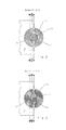
- Figur 1
- einen Rundbreithalter mit den wareneinlauf- und warenauslaufseitigen magnetischen Teilen,
- Figur 2
- eine Schnittdarstellung nach der Linie A-A der wareneinlaufseitigen magnetischen Teile in rotationssymmetrischer Ausführung und
- Figur 3
- eine Schnittdarstellung nach der Linie A-A der wareneinlaufseitigen magnetischen Teile in ovaler Ausführung.
Gemäß Figur 1 und 3 besitzt der Rundbreithalter 1 auf der Einlaufseite der Schlauchware 2 ein ovales Einlaufteil 7a.
Auf der Auslaufseite der Schlauchware 2 ist ein Auslaufteil 8 mit dem zentralen Träger 3 verbunden. Das Auslaufteil 8 besteht hier beispielsweise aus zwei miteinander verbundenen kegelstumpfförmigen oder ovalen Körpern.
In dem wareneinlaufseitig des Rundbreithalters vorhandenen kegelstumpfförmigen Endstück 7 sind Magnete gleicher Polarität integriert. Das kegelstumpfförmige Endstück 7 ist von wenigstens einem ersten und einem zweiten Halbringsegment 10, siehe auch Figur 2, unter Ausbildung eines Warenführungsspaltes 11 umgriffen. Die beiden Halbringsegmente 10 bilden mit Magneten bestückte Teile aus, die zusammen einen keglig gestalteten Durchgang als Gegenstück zu den kegelstumpfförmigen oder ovalen Endstück schaffen.
Die Magnete der bestückten Teile 10 sind gleicher Polarität.
In dem warenauslaufseitig des Rundbreithalters vorhandenen Einlaufteils 7 sind Magnete gleicher Polarität integriert. Das Einlaufteil 7 ist von wenigstens einem ersten und einem zweiten halbringartigen Körper 12 radial unter Ausbildung eines Warenführungsspaltes 13 umgriffen, dessen Innenkontur annähernd spiegelbildlich zur Außenkontur des
Auslaufteils 8 ausgebildet ist.
Der Körper 12 ist mit Magneten gleicher Polarität ausgerüstet.
Claims (13)
- Rundbreithalter (1) zum Behandeln textiler Schlauchware (2), umfassend:· einen zentralen, teleskopartig ausgebildeten Träger (3) mit dem in wenigstens einer ersten und einer zweiten vertikalen Ebene radial spreizbare Abstützungen (4) verbunden sind,· von den Abstützungen (4) getragene Streben (5) mit die Schlauchware (2) führenden Führungselementen (6),· wenigstens ein an einem ersten Ende des Trägers (3) angeordnetes Schlauchware-Einlaufteil (7),· wenigstens ein an einem zweiten Ende des Trägers (3) angeordnetes Schlauchware-Auslaufteil (8) und· eine wahlweise an dem Schlauchware-Einlauf- oder -Auslaufteil angreifende Hubeinrichtung (9), dadurch gekennzeichnet, dass· sowohl das wenigstens eine Schlauchware-Einlaufteil (7) als auch das wenigstens eine Schlauchware-Auslaufteil (8) erste mit Magneten bestückte Teile sind,· ein zweites mit Magneten bestücktes Teil (10) das Schlauchware-Einlaufteil (7) unter Ausbildung eines Warenführungsspaltes (11) umgreift,· ein zweites mit Magneten bestücktes Teil (12) das Schlauchware-Auslaufteil (8) unter Ausbildung eines Warenführungsspaltes (13) umgreift,und wobei die Magnete der Teile (7,10;8,12) gleiche Polarität aufweisen.
- Rundbreithalter nach Anspruch 1, dadurch gekennzeichnet, dass die Magnete der Teile (7,10;8,12) Permanentmagnete sind.
- Rundbreithalter nach Anspruch 1, dadurch gekennzeichnet, dass die Magnete der Teile (7,10;8,12) Elektromagnete sind.
- Rundbreithalter nach Anspruch 1, dadurch gekennzeichnet, dass die Magnete der Teile (7;8) Permanentmagnete sind und die Magnete der Teile (10;12) Elektromagnete sind.
- Rundbreithalter nach Anspruch 1, dadurch gekennzeichnet, dass zur Änderung des Warenführungsspaltes (11,13) die Teile (10,12) relativ zu den Teilen (7,8) in ihrer Position veränderbar sind.
- Rundbreithalter nach Anspruch 1, dadurch gekennzeichnet, dass die Teile (7,8) rotationssymmetrische Körper sind, die eine zur Ausbildung des Warenführungsspaltes (11,13) in Richtung der Warenführung verlaufende, geeignete Außenkontur aufweisen.
- Rundbreithalter nach Anspruch 1, dadurch gekennzeichnet, dass die Teile (7,8) ovale Körper (7a) sind, die eine zur Ausbildung des Warenführungsspaltes (11,13) in Richtung der Warenführung verlaufende, geeignete Außenkontur aufweisen.
- Rundbreithalter nach Anspruch 1, dadurch gekennzeichnet, dass die Teile (10,12) eine zur Außenkontur der Teile (7,8) spiegelbildliche Innenkontur besitzen.
- Rundbreithalter nach Anspruch 1, dadurch gekennzeichnet, dass die Einlaufteile (7,10) und die Auslaufteile (8,12) identisch gestaltet sind.
- Rundbreithalter nach Anspruch 1, dadurch gekennzeichnet, dass die Einlaufteile (7,10) und die Auslaufteile (8,12) verschieden gestaltet sind.
- Rundbreithalter nach Anspruch 3, dadurch gekennzeichnet, dass die Stärke der elektromagnetischen Kräfte veränderbar ist.
- Rundbreithalter nach Anspruch 4, dadurch gekennzeichnet, dass bei einer Kombination von Teilen einerseits mit Elektromagneten und andererseits mit Permanentmagneten die Stärke der elektromagnetischen Kräfte veränderbar ist.
- Rundbreithalter nach Anspruch 1, dadurch gekennzeichnet, dass wenigstens der Verlauf der Kontur des oberen Spaltes (13) so ausgebildet ist, dass der Rundbreithalter sowohl in axialer als auch in radialer Richtung fixiert ist.
Applications Claiming Priority (2)
| Application Number | Priority Date | Filing Date | Title |
|---|---|---|---|
| DE10153691 | 2001-10-31 | ||
| DE10153691A DE10153691C2 (de) | 2001-10-31 | 2001-10-31 | Rundbreithalter zum Behandeln textilen Schlauchware |
Publications (3)
| Publication Number | Publication Date |
|---|---|
| EP1308549A2 true EP1308549A2 (de) | 2003-05-07 |
| EP1308549A3 EP1308549A3 (de) | 2004-11-17 |
| EP1308549B1 EP1308549B1 (de) | 2008-03-26 |
Family
ID=7704302
Family Applications (1)
| Application Number | Title | Priority Date | Filing Date |
|---|---|---|---|
| EP02020625A Expired - Lifetime EP1308549B1 (de) | 2001-10-31 | 2002-09-13 | Rundbreithalter zum Behandeln textiler Schlauchware |
Country Status (5)
| Country | Link |
|---|---|
| US (1) | US6615462B2 (de) |
| EP (1) | EP1308549B1 (de) |
| JP (1) | JP3776396B2 (de) |
| AT (1) | ATE390504T1 (de) |
| DE (2) | DE10153691C2 (de) |
Cited By (4)
| Publication number | Priority date | Publication date | Assignee | Title |
|---|---|---|---|---|
| WO2004104287A1 (de) * | 2003-05-17 | 2004-12-02 | Lindauer Dornier Gesellschaft Mbh | Behandlungseinheit für textile schlauchware |
| WO2006066550A1 (de) * | 2004-12-23 | 2006-06-29 | Lindauer Dornier Gesellschaft Mbh | Rundbreithalter zum behandeln textiler schlauchware |
| CN101294330B (zh) * | 2007-04-23 | 2011-08-10 | 林进泳 | 卷布机撑布架改进结构 |
| CN103352315A (zh) * | 2013-05-22 | 2013-10-16 | 青岛即发集团股份有限公司 | 一种安装在针织圆机上的同步圆筒定型装置 |
Families Citing this family (4)
| Publication number | Priority date | Publication date | Assignee | Title |
|---|---|---|---|---|
| DE10322231B3 (de) * | 2003-05-17 | 2004-11-11 | Lindauer Dornier Gmbh | Behandlungseinheit für textile Schlauchware |
| KR100838927B1 (ko) | 2007-04-10 | 2008-06-16 | 신동호 | 원통 직물의 이동 가이드 장치 |
| GR1008282B (el) * | 2013-07-18 | 2014-09-02 | Γεωργιος Γεωργιου Λαγογιαννης | Σταθεροποιητης συστροφης πλεξης |
| CN116695371B (zh) * | 2023-08-09 | 2024-01-12 | 江苏恒力化纤股份有限公司 | 一种管状织物的热定型方法 |
Family Cites Families (18)
| Publication number | Priority date | Publication date | Assignee | Title |
|---|---|---|---|---|
| US2507599A (en) * | 1947-03-20 | 1950-05-16 | American Viscose Corp | Tubular fabric spreader |
| US2517067A (en) * | 1947-03-28 | 1950-08-01 | American Viscose Corp | Overfeed and internal expander for fabric in tubular form |
| US2623263A (en) * | 1949-04-15 | 1952-12-30 | Dungler Julien | Apparatus for stretching and guiding tubular textile articles |
| DE2106455A1 (en) * | 1971-02-11 | 1972-08-24 | Fa. B. Thies, 4420 Coesfeld | Tubular fabric spreaders - operating in magnetic fields |
| US3955251A (en) * | 1974-10-29 | 1976-05-11 | Warren Hogendyk | Fabric spreading and stretching apparatus |
| DE2926117C2 (de) * | 1979-06-28 | 1982-08-26 | Lindauer Dornier-Gesellschaft Mbh, 8990 Lindau | Von außen gehaltener zylindrischer Breithalter für Schlauchware |
| DE2935374C2 (de) | 1979-09-01 | 1981-01-08 | Lindauer Dornier Gesellschaft Mbh, 8990 Lindau | Von außen gehaltener zylindrischer Breithalter für Schlauchware |
| DE3048957C2 (de) * | 1980-12-24 | 1985-01-31 | Lindauer Dornier Gmbh, 8990 Lindau | Trockenanlage für textile Schlauchware |
| US4473929A (en) * | 1981-04-17 | 1984-10-02 | Green Sanford M | Magnetically cushioned cloth tentering device |
| DE3325918C2 (de) * | 1983-07-19 | 1985-01-24 | Lindauer Dornier Gmbh, 8990 Lindau | Trockenanlage für textile Schlauchware |
| FR2592897B1 (fr) * | 1986-01-15 | 1989-02-24 | Auffredou Jean Michel | Elargisseur universel pour l'etalement du tricot tubulaire. |
| DE3732754C1 (de) | 1987-09-29 | 1989-04-20 | Dornier Gmbh Lindauer | Von aussen gehaltener Rundbreithalter fuer textile Schlauchware |
| DE4109885A1 (de) * | 1991-03-26 | 1992-10-01 | Wintermantel Erich Dipl Volksw | Verfahren zur herstellung von hohlprofilen aus mehrlagigen vormaterialien, insbesondere aus geweben, gewirken, gelegen und bahnen sowie nach diesen verfahren hergestellte hohlprofile |
| DE19701415C1 (de) | 1997-01-17 | 1998-01-29 | Dornier Gmbh Lindauer | Vorrichtung zum Breithalten und Quetschen von Schlauch-Wirkware |
| IT1294995B1 (it) * | 1997-09-08 | 1999-04-27 | Sperotto Rimar Spa | Dispositivo allargatore perfezionato per tessuti a maglia tubolare |
| DE19912754A1 (de) | 1998-04-29 | 2000-09-28 | Dornier Gmbh Lindauer | Verbesserte Anlage zum Behandeln schlauchförmiger Maschenware |
| IT1303701B1 (it) * | 1998-11-04 | 2001-02-23 | Ferraro Spa | Allargatore di tessuti tubolari con attrazione magnetica. |
| IT1303700B1 (it) * | 1998-11-04 | 2001-02-23 | Ferraro Spa | Allargatore a smontaggio rapido per tessuti tubolari. |
-
2001
- 2001-10-31 DE DE10153691A patent/DE10153691C2/de not_active Expired - Fee Related
-
2002
- 2002-09-13 AT AT02020625T patent/ATE390504T1/de not_active IP Right Cessation
- 2002-09-13 DE DE50211954T patent/DE50211954D1/de not_active Expired - Fee Related
- 2002-09-13 EP EP02020625A patent/EP1308549B1/de not_active Expired - Lifetime
- 2002-10-29 US US10/283,917 patent/US6615462B2/en not_active Expired - Fee Related
- 2002-10-30 JP JP2002315659A patent/JP3776396B2/ja not_active Expired - Fee Related
Cited By (4)
| Publication number | Priority date | Publication date | Assignee | Title |
|---|---|---|---|---|
| WO2004104287A1 (de) * | 2003-05-17 | 2004-12-02 | Lindauer Dornier Gesellschaft Mbh | Behandlungseinheit für textile schlauchware |
| WO2006066550A1 (de) * | 2004-12-23 | 2006-06-29 | Lindauer Dornier Gesellschaft Mbh | Rundbreithalter zum behandeln textiler schlauchware |
| CN101294330B (zh) * | 2007-04-23 | 2011-08-10 | 林进泳 | 卷布机撑布架改进结构 |
| CN103352315A (zh) * | 2013-05-22 | 2013-10-16 | 青岛即发集团股份有限公司 | 一种安装在针织圆机上的同步圆筒定型装置 |
Also Published As
| Publication number | Publication date |
|---|---|
| ATE390504T1 (de) | 2008-04-15 |
| DE50211954D1 (de) | 2008-05-08 |
| EP1308549A3 (de) | 2004-11-17 |
| JP3776396B2 (ja) | 2006-05-17 |
| US6615462B2 (en) | 2003-09-09 |
| DE10153691A1 (de) | 2003-06-05 |
| JP2003193357A (ja) | 2003-07-09 |
| EP1308549B1 (de) | 2008-03-26 |
| DE10153691C2 (de) | 2003-09-18 |
| US20030079322A1 (en) | 2003-05-01 |
Similar Documents
| Publication | Publication Date | Title |
|---|---|---|
| DE68923975T2 (de) | Säulenfilter mit Bündeln langer Fasern. | |
| DE3131545A1 (de) | "vorrichtung zum auftragen von schaum" | |
| DE10153691C2 (de) | Rundbreithalter zum Behandeln textilen Schlauchware | |
| DE8218000U1 (de) | Vorrichtung zum waschen von gemuese, fruechten oder aehnlichen produkten | |
| DE2645521A1 (de) | Einrichtung zum behandeln von pulpe in einem behaelter | |
| DE2849352A1 (de) | Membran-druckfilter | |
| DE3043011C2 (de) | Vorrichtung zum kontinuierlichen Extrahieren von Flüssigkeit aus strömenden Suspensionen | |
| EP1814643B1 (de) | Rückspülfilter und zugehöriges filterelement | |
| DE1144691B (de) | Trommelsieb- oder Bandsiebmaschine | |
| DE3732754C1 (de) | Von aussen gehaltener Rundbreithalter fuer textile Schlauchware | |
| DE2732263A1 (de) | Vorrichtung zum herstellen einer sicke am umfang eines hohlzylinders | |
| AT395669B (de) | Egge | |
| DE2543912A1 (de) | Ankerbolzen | |
| CH645143A5 (de) | Von aussen gehaltener zylindrischer breithalter fuer schlauchware. | |
| DE10322231B3 (de) | Behandlungseinheit für textile Schlauchware | |
| EP0110129A2 (de) | Verlegegerät von Bruchfalten in schlauchförmigem Textilgut | |
| DE2225562C3 (de) | Schrumpfhülse zum Stabilisieren oder Färben von Textilfäden | |
| WO2004104287A1 (de) | Behandlungseinheit für textile schlauchware | |
| DE6918236U (de) | Breithalter zur behandlung von schlauchware. | |
| DE2712603A1 (de) | Verfahren und vorrichtung zur modifizierung der charakteristiken einer fluessigkeit | |
| DE1922938A1 (de) | Breithalter zur Behandlung von Schlauchware | |
| AT206217B (de) | Vorrichtung zum Sieben einer strömenden Flüssigkeit | |
| DE1773142C (de) | Prüfapparat für die Naßbehandlung von Textilmaterial | |
| DE6809090U (de) | Schneide- und entdoubliermaschine | |
| DE1258254B (de) | Sichter fuer Papierstoffsuspensionen |
Legal Events
| Date | Code | Title | Description |
|---|---|---|---|
| PUAI | Public reference made under article 153(3) epc to a published international application that has entered the european phase |
Free format text: ORIGINAL CODE: 0009012 |
|
| AK | Designated contracting states |
Designated state(s): AT BE BG CH CY CZ DE DK EE ES FI FR GB GR IE IT LI LU MC NL PT SE SK TR |
|
| AX | Request for extension of the european patent |
Extension state: AL LT LV MK RO SI |
|
| PUAL | Search report despatched |
Free format text: ORIGINAL CODE: 0009013 |
|
| AK | Designated contracting states |
Kind code of ref document: A3 Designated state(s): AT BE BG CH CY CZ DE DK EE ES FI FR GB GR IE IT LI LU MC NL PT SE SK TR |
|
| AX | Request for extension of the european patent |
Extension state: AL LT LV MK RO SI |
|
| 17P | Request for examination filed |
Effective date: 20050124 |
|
| AKX | Designation fees paid |
Designated state(s): AT BE BG CH CY CZ DE DK EE ES FI FR GB GR IE IT LI LU MC NL PT SE SK TR |
|
| 17Q | First examination report despatched |
Effective date: 20061128 |
|
| 17Q | First examination report despatched |
Effective date: 20061128 |
|
| GRAP | Despatch of communication of intention to grant a patent |
Free format text: ORIGINAL CODE: EPIDOSNIGR1 |
|
| GRAS | Grant fee paid |
Free format text: ORIGINAL CODE: EPIDOSNIGR3 |
|
| GRAA | (expected) grant |
Free format text: ORIGINAL CODE: 0009210 |
|
| AK | Designated contracting states |
Kind code of ref document: B1 Designated state(s): AT BE BG CH CY CZ DE DK EE ES FI FR GB GR IE IT LI LU MC NL PT SE SK TR |
|
| REG | Reference to a national code |
Ref country code: GB Ref legal event code: FG4D Free format text: NOT ENGLISH |
|
| REG | Reference to a national code |
Ref country code: IE Ref legal event code: FG4D Free format text: LANGUAGE OF EP DOCUMENT: GERMAN Ref country code: CH Ref legal event code: EP |
|
| REF | Corresponds to: |
Ref document number: 50211954 Country of ref document: DE Date of ref document: 20080508 Kind code of ref document: P |
|
| PG25 | Lapsed in a contracting state [announced via postgrant information from national office to epo] |
Ref country code: FI Free format text: LAPSE BECAUSE OF FAILURE TO SUBMIT A TRANSLATION OF THE DESCRIPTION OR TO PAY THE FEE WITHIN THE PRESCRIBED TIME-LIMIT Effective date: 20080326 |
|
| NLV1 | Nl: lapsed or annulled due to failure to fulfill the requirements of art. 29p and 29m of the patents act | ||
| REG | Reference to a national code |
Ref country code: IE Ref legal event code: FD4D |
|
| PG25 | Lapsed in a contracting state [announced via postgrant information from national office to epo] |
Ref country code: SE Free format text: LAPSE BECAUSE OF FAILURE TO SUBMIT A TRANSLATION OF THE DESCRIPTION OR TO PAY THE FEE WITHIN THE PRESCRIBED TIME-LIMIT Effective date: 20080626 Ref country code: CZ Free format text: LAPSE BECAUSE OF FAILURE TO SUBMIT A TRANSLATION OF THE DESCRIPTION OR TO PAY THE FEE WITHIN THE PRESCRIBED TIME-LIMIT Effective date: 20080326 Ref country code: PT Free format text: LAPSE BECAUSE OF FAILURE TO SUBMIT A TRANSLATION OF THE DESCRIPTION OR TO PAY THE FEE WITHIN THE PRESCRIBED TIME-LIMIT Effective date: 20080901 Ref country code: SK Free format text: LAPSE BECAUSE OF FAILURE TO SUBMIT A TRANSLATION OF THE DESCRIPTION OR TO PAY THE FEE WITHIN THE PRESCRIBED TIME-LIMIT Effective date: 20080326 Ref country code: ES Free format text: LAPSE BECAUSE OF FAILURE TO SUBMIT A TRANSLATION OF THE DESCRIPTION OR TO PAY THE FEE WITHIN THE PRESCRIBED TIME-LIMIT Effective date: 20080707 |
|
| PG25 | Lapsed in a contracting state [announced via postgrant information from national office to epo] |
Ref country code: NL Free format text: LAPSE BECAUSE OF FAILURE TO SUBMIT A TRANSLATION OF THE DESCRIPTION OR TO PAY THE FEE WITHIN THE PRESCRIBED TIME-LIMIT Effective date: 20080326 |
|
| PGFP | Annual fee paid to national office [announced via postgrant information from national office to epo] |
Ref country code: IT Payment date: 20080911 Year of fee payment: 7 |
|
| EN | Fr: translation not filed | ||
| PG25 | Lapsed in a contracting state [announced via postgrant information from national office to epo] |
Ref country code: DK Free format text: LAPSE BECAUSE OF FAILURE TO SUBMIT A TRANSLATION OF THE DESCRIPTION OR TO PAY THE FEE WITHIN THE PRESCRIBED TIME-LIMIT Effective date: 20080326 Ref country code: IE Free format text: LAPSE BECAUSE OF FAILURE TO SUBMIT A TRANSLATION OF THE DESCRIPTION OR TO PAY THE FEE WITHIN THE PRESCRIBED TIME-LIMIT Effective date: 20080326 |
|
| PGFP | Annual fee paid to national office [announced via postgrant information from national office to epo] |
Ref country code: DE Payment date: 20080806 Year of fee payment: 7 |
|
| PLBE | No opposition filed within time limit |
Free format text: ORIGINAL CODE: 0009261 |
|
| STAA | Information on the status of an ep patent application or granted ep patent |
Free format text: STATUS: NO OPPOSITION FILED WITHIN TIME LIMIT |
|
| 26N | No opposition filed |
Effective date: 20081230 |
|
| BERE | Be: lapsed |
Owner name: LINDAUER DORNIER G.- M.B.H Effective date: 20080930 |
|
| PG25 | Lapsed in a contracting state [announced via postgrant information from national office to epo] |
Ref country code: BG Free format text: LAPSE BECAUSE OF FAILURE TO SUBMIT A TRANSLATION OF THE DESCRIPTION OR TO PAY THE FEE WITHIN THE PRESCRIBED TIME-LIMIT Effective date: 20080626 Ref country code: MC Free format text: LAPSE BECAUSE OF NON-PAYMENT OF DUE FEES Effective date: 20080930 Ref country code: EE Free format text: LAPSE BECAUSE OF FAILURE TO SUBMIT A TRANSLATION OF THE DESCRIPTION OR TO PAY THE FEE WITHIN THE PRESCRIBED TIME-LIMIT Effective date: 20080326 Ref country code: FR Free format text: LAPSE BECAUSE OF FAILURE TO SUBMIT A TRANSLATION OF THE DESCRIPTION OR TO PAY THE FEE WITHIN THE PRESCRIBED TIME-LIMIT Effective date: 20090116 |
|
| REG | Reference to a national code |
Ref country code: CH Ref legal event code: PL |
|
| GBPC | Gb: european patent ceased through non-payment of renewal fee |
Effective date: 20080913 |
|
| PG25 | Lapsed in a contracting state [announced via postgrant information from national office to epo] |
Ref country code: BE Free format text: LAPSE BECAUSE OF NON-PAYMENT OF DUE FEES Effective date: 20080930 |
|
| PG25 | Lapsed in a contracting state [announced via postgrant information from national office to epo] |
Ref country code: CY Free format text: LAPSE BECAUSE OF FAILURE TO SUBMIT A TRANSLATION OF THE DESCRIPTION OR TO PAY THE FEE WITHIN THE PRESCRIBED TIME-LIMIT Effective date: 20080326 |
|
| PG25 | Lapsed in a contracting state [announced via postgrant information from national office to epo] |
Ref country code: AT Free format text: LAPSE BECAUSE OF NON-PAYMENT OF DUE FEES Effective date: 20080913 Ref country code: CH Free format text: LAPSE BECAUSE OF NON-PAYMENT OF DUE FEES Effective date: 20080930 Ref country code: LI Free format text: LAPSE BECAUSE OF NON-PAYMENT OF DUE FEES Effective date: 20080930 |
|
| PG25 | Lapsed in a contracting state [announced via postgrant information from national office to epo] |
Ref country code: GB Free format text: LAPSE BECAUSE OF NON-PAYMENT OF DUE FEES Effective date: 20080913 |
|
| PG25 | Lapsed in a contracting state [announced via postgrant information from national office to epo] |
Ref country code: LU Free format text: LAPSE BECAUSE OF NON-PAYMENT OF DUE FEES Effective date: 20080913 Ref country code: DE Free format text: LAPSE BECAUSE OF NON-PAYMENT OF DUE FEES Effective date: 20100401 |
|
| PG25 | Lapsed in a contracting state [announced via postgrant information from national office to epo] |
Ref country code: TR Free format text: LAPSE BECAUSE OF FAILURE TO SUBMIT A TRANSLATION OF THE DESCRIPTION OR TO PAY THE FEE WITHIN THE PRESCRIBED TIME-LIMIT Effective date: 20080326 |
|
| PG25 | Lapsed in a contracting state [announced via postgrant information from national office to epo] |
Ref country code: GR Free format text: LAPSE BECAUSE OF FAILURE TO SUBMIT A TRANSLATION OF THE DESCRIPTION OR TO PAY THE FEE WITHIN THE PRESCRIBED TIME-LIMIT Effective date: 20080627 |
|
| PG25 | Lapsed in a contracting state [announced via postgrant information from national office to epo] |
Ref country code: IT Free format text: LAPSE BECAUSE OF NON-PAYMENT OF DUE FEES Effective date: 20090913 |