EP1308662A2 - Lösbare Schnellkupplung für mindestens eine Rohrleitung - Google Patents
Lösbare Schnellkupplung für mindestens eine Rohrleitung Download PDFInfo
- Publication number
- EP1308662A2 EP1308662A2 EP02356217A EP02356217A EP1308662A2 EP 1308662 A2 EP1308662 A2 EP 1308662A2 EP 02356217 A EP02356217 A EP 02356217A EP 02356217 A EP02356217 A EP 02356217A EP 1308662 A2 EP1308662 A2 EP 1308662A2
- Authority
- EP
- European Patent Office
- Prior art keywords
- tube
- ring
- window
- cap
- intended
- Prior art date
- Legal status (The legal status is an assumption and is not a legal conclusion. Google has not performed a legal analysis and makes no representation as to the accuracy of the status listed.)
- Granted
Links
Images



Classifications
-
- F—MECHANICAL ENGINEERING; LIGHTING; HEATING; WEAPONS; BLASTING
- F16—ENGINEERING ELEMENTS AND UNITS; GENERAL MEASURES FOR PRODUCING AND MAINTAINING EFFECTIVE FUNCTIONING OF MACHINES OR INSTALLATIONS; THERMAL INSULATION IN GENERAL
- F16L—PIPES; JOINTS OR FITTINGS FOR PIPES; SUPPORTS FOR PIPES, CABLES OR PROTECTIVE TUBING; MEANS FOR THERMAL INSULATION IN GENERAL
- F16L37/00—Couplings of the quick-acting type
- F16L37/08—Couplings of the quick-acting type in which the connection between abutting or axially overlapping ends is maintained by locking members
- F16L37/084—Couplings of the quick-acting type in which the connection between abutting or axially overlapping ends is maintained by locking members combined with automatic locking
- F16L37/092—Couplings of the quick-acting type in which the connection between abutting or axially overlapping ends is maintained by locking members combined with automatic locking by means of elements wedged between the pipe and the frusto-conical surface of the body of the connector
- F16L37/0925—Couplings of the quick-acting type in which the connection between abutting or axially overlapping ends is maintained by locking members combined with automatic locking by means of elements wedged between the pipe and the frusto-conical surface of the body of the connector with rings which bite into the wall of the pipe
-
- F—MECHANICAL ENGINEERING; LIGHTING; HEATING; WEAPONS; BLASTING
- F16—ENGINEERING ELEMENTS AND UNITS; GENERAL MEASURES FOR PRODUCING AND MAINTAINING EFFECTIVE FUNCTIONING OF MACHINES OR INSTALLATIONS; THERMAL INSULATION IN GENERAL
- F16L—PIPES; JOINTS OR FITTINGS FOR PIPES; SUPPORTS FOR PIPES, CABLES OR PROTECTIVE TUBING; MEANS FOR THERMAL INSULATION IN GENERAL
- F16L37/00—Couplings of the quick-acting type
- F16L37/08—Couplings of the quick-acting type in which the connection between abutting or axially overlapping ends is maintained by locking members
- F16L37/084—Couplings of the quick-acting type in which the connection between abutting or axially overlapping ends is maintained by locking members combined with automatic locking
- F16L37/092—Couplings of the quick-acting type in which the connection between abutting or axially overlapping ends is maintained by locking members combined with automatic locking by means of elements wedged between the pipe and the frusto-conical surface of the body of the connector
- F16L37/0926—Couplings of the quick-acting type in which the connection between abutting or axially overlapping ends is maintained by locking members combined with automatic locking by means of elements wedged between the pipe and the frusto-conical surface of the body of the connector with an inner support sleeve arranged within the pipe
-
- F—MECHANICAL ENGINEERING; LIGHTING; HEATING; WEAPONS; BLASTING
- F16—ENGINEERING ELEMENTS AND UNITS; GENERAL MEASURES FOR PRODUCING AND MAINTAINING EFFECTIVE FUNCTIONING OF MACHINES OR INSTALLATIONS; THERMAL INSULATION IN GENERAL
- F16L—PIPES; JOINTS OR FITTINGS FOR PIPES; SUPPORTS FOR PIPES, CABLES OR PROTECTIVE TUBING; MEANS FOR THERMAL INSULATION IN GENERAL
- F16L2201/00—Special arrangements for pipe couplings
- F16L2201/10—Indicators for correct coupling
Definitions
- the present invention relates to an instant connection removable for at least one tube, in particular a tube made of material thermoplastic or composite material, comprising a core metallic, for example aluminum, coated with layers of synthetic.
- This connection is used to make the connection between several tubes or between a tube and a device, such as a tap or a manifold. It is connection for tubes used in particular for conveying fluids servants.
- connection is known from EP 0 021 795.
- each tube is inserted into the connection, the sealing being achieved by an O-ring outside the tube, and the restraint being made using a ring material synthetic with radial arms equipped with claws towards the inside.
- connection has a number of disadvantages; the O-ring not being held in a groove, there are risks of displacement of the tube and the seal in the manner of a piston during pressure cyclic fluid or water hammer.
- the guide of the retaining ring is of poor quality because it is snapped into a housing made in the fitting body, with a big game.
- the claws of the retaining ring of the tube may remain planted in the material and make the connection difficult to dismantle.
- WO 9607048 relates to a coupling comprising a seal and an attachment ring located outside the tube. It should be noted that in this connection the snap ring compresses axially the seal, this phenomenon may be aggravated to the extent that the snap ring is driven by the tube during the connection. Gold this axial compression of the seal makes it difficult to introduce tube in the fitting.
- the object of the invention is to provide an instant connection allowing a disassembly of the tube, which is made compact and simple by having a small number of components, and which is economic to achieve.
- the hanging is realized by the ring by exerting a slight pull on the tube, this traction causing a tightening of the ring that axially immobilizes the tube in the fitting.
- the tube is pushed towards the inside of the fitting until its end comes into abutment inside the fitting, a tool through a window formed in the cap then allowing to axially immobilize the snap ring in a position in which it does not immobilize the tube, thus allowing the withdrawal thereof.
- the annular shoulder can be used for axial locking of the ring by a tool through a window.
- each window formed in the cap extends axially substantially from the collar of the body up to the shoulder of the ring when the studs of the latter bear against the collar.
- the shoulder of the ring is therefore in the zone of a window, in the retracted position of the ring, which allows, to achieve the dismantling of a tube, introducing a tool between the shoulder and the edge of the window located on the outside of the fitting.
- the tool intended to act through a window on the snap ring is an external tool such as a screwdriver whose end bears against the annular shoulder, for act on the snap ring.
- the tool intended to act through a window on the snap ring is constituted by a rider intended for at least partially surround the cap and having a finger turned inward, entering a window to engage between the shoulder of the snap ring and the edge of the window located side of the free end of the fitting.
- rider being realized in elastically deformable synthetic material to enable its implementation place and its withdrawal with respect to the cap, can be engaged on the cap and is automatically held in the axial locking position of the ring allowing the removal of the tube.
- the tool intended to act through a window on the snap ring is constituted by a rider intended to come at least partially surround the cap and having a turned finger inward, entering a window to engage between the collar of the body forming a stop and the rear edge of a ring stud when it is in the locking position.
- Such jumper is not intended to allow the disassembly of a tube, but contrary to ensuring the axial locking of the snap ring, in the locked position of the tube.
- This lock can be interesting in the case of installation at risk or in the case of major solicitation can be exerted on tubes and fittings.
- the tool intended to act through the window on the snap ring is constituted by a rider intended for at least partially surround the cap and having a finger turned inwards likely to take a first position in which the finger engages against the shoulder of the strap and the edge of the window located on the side of the free end of the fitting and a second position in which the finger engages between the collar of the body forming a stop and the rear edge of a stud of the snap ring, when it is in the locking position.
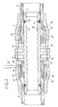
- FIG. 1 shows a coupling 2 for two tubes comprising a body 3 on which is engaged a cap 4.
- the body comprises, for each tube to be connected, a tubular portion 6 of corresponding section to the inside diameter of the tube, in which is provided a groove 7 for housing a gasket 8 to ensure sealing with the inside of the tube.
- a collar 9 is intended to serve stop at the end of each tube when introducing it on the corresponding tubular part.
- the cap 4 delimits with the body 3, and on the side of each tube a chamber 10 for housing a ring 12.
- Each chamber 10 comprises an annular portion, constant section narrowing on the side of the free end of the fitting by a surface 13 inclined from the outside to the inside and from the center from the fitting to the end of it.
- the cap 4 also includes, from each collar 9, a series of windows 14 formed on its periphery.
- Each attachment ring 12 comprises a cylindrical body from which axially extend several teeth 15 separated one others by slots 16, each tooth having at its end free, on the one hand an outside face 17 inclined from the outside towards inside and from behind to the front, intended to cooperate with a surface 13 of a cap, and secondly, on the inner side, a ridge 18 intended to penetrate the outer surface of the wall of the tube to connected.
- the body of the snap ring has a shoulder annular 19 continuous or not, from which extend towards the rear of studs 20 intended to bear against a flange 9 of the body.
- Each window formed in the cap extends axially, substantially from a flange 9 of the body 3 to beyond the shoulder of the snap ring, when the studs thereof are in support against the collar.
- Figures 4 and 5 show a tool adapted to immobilize axially a fastening ring 12 during removal of a tube.
- This tool is constituted by a rider 23 made of elastic synthetic material deformable, comprising a handling pallet 24, from which extend two rounded branches.
- the branches carry at least one finger 25 turned radially inwards and intended to engage between the shoulder 19 of the snap ring and the edge of the window located on the free side of the fitting, as shown in Figure 5.
- Figures 6 and 7 represent another tool for immobilize a snap ring in the locked position of a tube.
- This tool is constituted by a jumper 26 made of a synthetic material elastically deformable.
- This jumper 26 includes a palette of handling 27 from which extend two rounded branches each bearing at least one finger 28 directed radially inwardly and intended to enter a window 14 to engage between the flange 9 of the body forming abutment and the rear edge of a stud of the ring hanging, or the shoulder of the same ring. It is not so possible to push the tube back inside the fitting to allow its withdrawal out of the tube.
- Figures 8 and 9 represent another tool.
- This tool is constituted by a jumper 29 made of deformable synthetic material elastically.
- the rider 29 whose structure is similar to that of riders 23 and 26 includes a pallet handling from which extends two rounded hips each of which carries at least a finger 30 directed radially inwards.
- Jumper 29 has a dual function. Indeed, as the 8, the finger 30 engages between the shoulder 19 of the hanging ring and the edge of the window located on the free side of the fitting. The attachment ring 12 is thus immobilized during removal of a tube. As shown in FIG. 9, the same jumper 29 can be returned from such that the finger 30 enters the window 14 to engage between the flange 9 and the rear edge of a stud of the snap ring, or the shoulder of this same ring. The snap ring is thus immobilized in locked position of a tube.
- the invention provides a great improvement to the existing technique by providing a fitting removable snapshot of very simple structure, realized in a economic from a small number of parts, and a very use convenient for the operator, to maintain the ring (s) latching in the unlocked position to mount blanks, or to disassemble the fitting, and to lock and hold the tubes in locked position, when needed.
Landscapes
- Engineering & Computer Science (AREA)
- General Engineering & Computer Science (AREA)
- Mechanical Engineering (AREA)
- Quick-Acting Or Multi-Walled Pipe Joints (AREA)
- Non-Disconnectible Joints And Screw-Threaded Joints (AREA)
- Joints That Cut Off Fluids, And Hose Joints (AREA)
- Infusion, Injection, And Reservoir Apparatuses (AREA)
- External Artificial Organs (AREA)
- Mutual Connection Of Rods And Tubes (AREA)
- Containers And Packaging Bodies Having A Special Means To Remove Contents (AREA)
Applications Claiming Priority (2)
| Application Number | Priority Date | Filing Date | Title |
|---|---|---|---|
| FR0114155 | 2001-10-31 | ||
| FR0114155A FR2831643B1 (fr) | 2001-10-31 | 2001-10-31 | Raccord instantane demontable pour au moins un tube |
Publications (3)
| Publication Number | Publication Date |
|---|---|
| EP1308662A2 true EP1308662A2 (de) | 2003-05-07 |
| EP1308662A3 EP1308662A3 (de) | 2003-10-15 |
| EP1308662B1 EP1308662B1 (de) | 2004-11-17 |
Family
ID=8868977
Family Applications (1)
| Application Number | Title | Priority Date | Filing Date |
|---|---|---|---|
| EP02356217A Expired - Lifetime EP1308662B1 (de) | 2001-10-31 | 2002-10-30 | Lösbare Schnellkupplung für mindestens eine Rohrleitung |
Country Status (6)
| Country | Link |
|---|---|
| EP (1) | EP1308662B1 (de) |
| AT (1) | ATE282788T1 (de) |
| DE (1) | DE60201959T2 (de) |
| ES (1) | ES2231661T3 (de) |
| FR (1) | FR2831643B1 (de) |
| PT (1) | PT1308662E (de) |
Cited By (11)
| Publication number | Priority date | Publication date | Assignee | Title |
|---|---|---|---|---|
| FR2855589A1 (fr) * | 2003-05-28 | 2004-12-03 | Legris Sa | Dispositif de raccordement instantane |
| WO2006126774A1 (en) * | 2005-04-23 | 2006-11-30 | Andong Zion Foudation Of Social Welfare Facilities | Holder for pipe fittings |
| WO2007004861A1 (en) * | 2005-07-03 | 2007-01-11 | Widee B.V. | Coupling between two bodies comprising an elastically deformable cutting ring with a screw thread forming cutting lips |
| NL1029414C2 (nl) * | 2005-07-03 | 2007-01-19 | Widee Bv | Koppeling tussen twee lichamen, omvattende een elastisch deformeerbare snijring met een snijlippen vormende schroefdraad. |
| GB2431209A (en) * | 2005-10-14 | 2007-04-18 | Hepworth Building Prod | Pipe insert for multi-layered pipe |
| EP2112416A1 (de) | 2008-04-25 | 2009-10-28 | Comap | Steckanschluss für mindestens ein Rohr |
| US8056937B2 (en) | 2006-12-12 | 2011-11-15 | John Guest International Limited | Tube couplings |
| FR2969737A1 (fr) * | 2012-04-16 | 2012-06-29 | Parker Hannifin Mfg France | Dispositif et procede pour remplacer un tube definissant une portion de circuit de transport de fluide |
| CN101761719B (zh) * | 2009-08-11 | 2013-06-19 | 叶炎彬 | 快捷式管道连接器 |
| US9157643B2 (en) | 2010-10-14 | 2015-10-13 | Fimcim S.P.A. | Conditioning plant |
| US9611958B1 (en) | 2007-01-05 | 2017-04-04 | Zurn Industries, Llc | Combination mechanical/fusion pipe fitting with push connect coupling arrangement |
Families Citing this family (6)
| Publication number | Priority date | Publication date | Assignee | Title |
|---|---|---|---|---|
| NZ531121A (en) * | 2004-02-12 | 2004-10-29 | Mm Kembla New Zealand Ltd | Push-in pipe connector with pretension spring between collar-and-fingers component and connector |
| DE202007011229U1 (de) | 2007-08-11 | 2008-12-24 | Uponor Innovation Ab | Steckfitting für ein Rohr, insbesondere Kunststoffrohr oder Kunststoff-Metall-Verbundrohr |
| EP2256394A1 (de) * | 2009-05-29 | 2010-12-01 | Wavin B.V. | Lösewerkzeug für eine Steckverbindung von Rohren |
| IL259057B (en) * | 2018-04-30 | 2019-11-28 | Efraim Natan | Releasable connector |
| FR3114370A1 (fr) * | 2020-09-22 | 2022-03-25 | Comap | Raccord instantané pour tubes |
| AU2022202293B1 (en) * | 2022-04-06 | 2023-01-05 | Philmac Pty Ltd | A push-fit pipe fitting with a visual indicator |
Family Cites Families (3)
| Publication number | Priority date | Publication date | Assignee | Title |
|---|---|---|---|---|
| US2423632A (en) * | 1943-10-21 | 1947-07-08 | Eastman Mfg Company | Coupling |
| US3097866A (en) * | 1960-11-14 | 1963-07-16 | Weatherhead Co | Pressurized hose end |
| JP2779866B2 (ja) * | 1990-03-23 | 1998-07-23 | ニッタ・ムアー株式会社 | 管継手 |
-
2001
- 2001-10-31 FR FR0114155A patent/FR2831643B1/fr not_active Expired - Lifetime
-
2002
- 2002-10-30 EP EP02356217A patent/EP1308662B1/de not_active Expired - Lifetime
- 2002-10-30 ES ES02356217T patent/ES2231661T3/es not_active Expired - Lifetime
- 2002-10-30 PT PT02356217T patent/PT1308662E/pt unknown
- 2002-10-30 AT AT02356217T patent/ATE282788T1/de active
- 2002-10-30 DE DE60201959T patent/DE60201959T2/de not_active Expired - Lifetime
Cited By (18)
| Publication number | Priority date | Publication date | Assignee | Title |
|---|---|---|---|---|
| WO2004109175A1 (fr) * | 2003-05-28 | 2004-12-16 | Legris Sa | Dispositif de raccordement instantane |
| KR100712030B1 (ko) * | 2003-05-28 | 2007-04-27 | 레그리스소시에떼아노님 | 순간 연결 장치 |
| US7448655B2 (en) | 2003-05-28 | 2008-11-11 | Legris Sa | Instantaneous connection device |
| FR2855589A1 (fr) * | 2003-05-28 | 2004-12-03 | Legris Sa | Dispositif de raccordement instantane |
| CN1795346B (zh) * | 2003-05-28 | 2010-12-01 | 勒格里股份有限公司 | 瞬间偶联装置 |
| WO2006126774A1 (en) * | 2005-04-23 | 2006-11-30 | Andong Zion Foudation Of Social Welfare Facilities | Holder for pipe fittings |
| WO2007004861A1 (en) * | 2005-07-03 | 2007-01-11 | Widee B.V. | Coupling between two bodies comprising an elastically deformable cutting ring with a screw thread forming cutting lips |
| NL1029414C2 (nl) * | 2005-07-03 | 2007-01-19 | Widee Bv | Koppeling tussen twee lichamen, omvattende een elastisch deformeerbare snijring met een snijlippen vormende schroefdraad. |
| GB2431209A (en) * | 2005-10-14 | 2007-04-18 | Hepworth Building Prod | Pipe insert for multi-layered pipe |
| US8056937B2 (en) | 2006-12-12 | 2011-11-15 | John Guest International Limited | Tube couplings |
| US9611958B1 (en) | 2007-01-05 | 2017-04-04 | Zurn Industries, Llc | Combination mechanical/fusion pipe fitting with push connect coupling arrangement |
| EP2112416A1 (de) | 2008-04-25 | 2009-10-28 | Comap | Steckanschluss für mindestens ein Rohr |
| RU2477414C2 (ru) * | 2008-04-25 | 2013-03-10 | Комап | Быстроразъемная муфта для одной или нескольких труб |
| CN101761719B (zh) * | 2009-08-11 | 2013-06-19 | 叶炎彬 | 快捷式管道连接器 |
| US9157643B2 (en) | 2010-10-14 | 2015-10-13 | Fimcim S.P.A. | Conditioning plant |
| US9506662B2 (en) | 2010-10-14 | 2016-11-29 | Fimcim S.P.A. | Conditioning plant |
| EP2653441A1 (de) | 2012-04-16 | 2013-10-23 | Parker Hannifin Manufacturing France SAS | Vorrichtung und Verfahren zum Ersetzen eines Rohrs, das einen Abschnitt eines Flüssigkeitskreislaufsystems darstellt |
| FR2969737A1 (fr) * | 2012-04-16 | 2012-06-29 | Parker Hannifin Mfg France | Dispositif et procede pour remplacer un tube definissant une portion de circuit de transport de fluide |
Also Published As
| Publication number | Publication date |
|---|---|
| FR2831643B1 (fr) | 2004-06-04 |
| EP1308662B1 (de) | 2004-11-17 |
| EP1308662A3 (de) | 2003-10-15 |
| PT1308662E (pt) | 2005-02-28 |
| ES2231661T3 (es) | 2005-05-16 |
| FR2831643A1 (fr) | 2003-05-02 |
| ATE282788T1 (de) | 2004-12-15 |
| DE60201959T2 (de) | 2005-11-03 |
| DE60201959D1 (de) | 2004-12-23 |
Similar Documents
| Publication | Publication Date | Title |
|---|---|---|
| EP1308662B1 (de) | Lösbare Schnellkupplung für mindestens eine Rohrleitung | |
| EP0723103B1 (de) | Vorrichtung zum schnellen Verbinden eines Rohres mit einem starren Element | |
| EP1064489B1 (de) | Steck-kupplung für rohre | |
| EP0715111B1 (de) | Schnellverbindungsvorrichtung zum Kuppeln eines Rohres auf einem starren Ansatzstück | |
| EP0488844B1 (de) | Anschlussvorrichtung, insbesondere zur Verbindung eines Schlauches mit einem Automobilwärmeaustauscher | |
| EP1328750B1 (de) | Anschlussanordnung mit einer schnellkupplung zum verbinden von einem leitungsende mit einem anschlussteil und vorrichtung zum schutz der verbindung | |
| EP1627173B1 (de) | Schnellverbindungsvorrichtung | |
| EP0510240A1 (de) | Steckverbinder-Vorrichtung | |
| FR2965887A1 (fr) | Dispositif de raccord avec verrouillage par griffes filetees et raccord comprenant un tel dispositif | |
| EP2615348A2 (de) | Steckanschluss | |
| EP1692427A1 (de) | Schnellverbindungsvorrichtung | |
| EP1273843A1 (de) | Wiederverwendbare Kupplung zum Verbinden von verstärkten Schlauchenden | |
| EP1258666B1 (de) | Schnellkupplung mit Befestigung durch elastischen, äusseren Ring | |
| EP0740101B1 (de) | Schnellkupplung mit einem selbständig belasteten Ventil | |
| EP1291568B1 (de) | Schnellkupplung für verformbare Rohre | |
| FR2683017A1 (fr) | Raccord pour tubes. | |
| EP4124788A1 (de) | Steckanschlusselement eines fluidanschlusses und ein solches steckelement umfassender fluidanschluss | |
| EP0989348B1 (de) | Vorrichtung zum Schnellverbinden von Rohren | |
| FR2675999A1 (fr) | Seringue de securite. | |
| FR2891889A1 (fr) | Embout de connexion etanche et piece terminale pour un tel embout | |
| EP0811797B1 (de) | Sicherheitsschnellkupplung für die lösbare Verbindung von Rohrleitungen | |
| FR2746893A1 (fr) | Raccord pour la connexion de tubulures pour le transport de fluides | |
| FR2796122A1 (fr) | Raccord instantane pour tube composite a ame metallique | |
| FR2578621A1 (fr) | Dispositif de raccordement amovible pour tuyaux | |
| FR2712062A1 (fr) | Dispositif destiné au passage d'une canalisation au travers d'une paroi. |
Legal Events
| Date | Code | Title | Description |
|---|---|---|---|
| PUAI | Public reference made under article 153(3) epc to a published international application that has entered the european phase |
Free format text: ORIGINAL CODE: 0009012 |
|
| AK | Designated contracting states |
Designated state(s): AT BE BG CH CY CZ DE DK EE ES FI FR GB GR IE IT LI LU MC NL PT SE SK TR |
|
| AX | Request for extension of the european patent |
Extension state: AL LT LV MK RO SI |
|
| PUAL | Search report despatched |
Free format text: ORIGINAL CODE: 0009013 |
|
| AK | Designated contracting states |
Kind code of ref document: A3 Designated state(s): AT BE BG CH CY CZ DE DK EE ES FI FR GB GR IE IT LI LU MC NL PT SE SK TR |
|
| AX | Request for extension of the european patent |
Extension state: AL LT LV MK RO SI |
|
| 17P | Request for examination filed |
Effective date: 20040301 |
|
| GRAP | Despatch of communication of intention to grant a patent |
Free format text: ORIGINAL CODE: EPIDOSNIGR1 |
|
| AKX | Designation fees paid |
Designated state(s): AT BE BG CH CY CZ DE DK EE ES FI FR GB GR IE IT LI LU MC NL PT SE SK TR |
|
| GRAS | Grant fee paid |
Free format text: ORIGINAL CODE: EPIDOSNIGR3 |
|
| GRAA | (expected) grant |
Free format text: ORIGINAL CODE: 0009210 |
|
| AK | Designated contracting states |
Kind code of ref document: B1 Designated state(s): AT BE BG CH CY CZ DE DK EE ES FI FR GB GR IE IT LI LU MC NL PT SE SK TR |
|
| PG25 | Lapsed in a contracting state [announced via postgrant information from national office to epo] |
Ref country code: SK Free format text: LAPSE BECAUSE OF FAILURE TO SUBMIT A TRANSLATION OF THE DESCRIPTION OR TO PAY THE FEE WITHIN THE PRESCRIBED TIME-LIMIT Effective date: 20041117 Ref country code: TR Free format text: LAPSE BECAUSE OF FAILURE TO SUBMIT A TRANSLATION OF THE DESCRIPTION OR TO PAY THE FEE WITHIN THE PRESCRIBED TIME-LIMIT Effective date: 20041117 Ref country code: FI Free format text: LAPSE BECAUSE OF FAILURE TO SUBMIT A TRANSLATION OF THE DESCRIPTION OR TO PAY THE FEE WITHIN THE PRESCRIBED TIME-LIMIT Effective date: 20041117 Ref country code: IE Free format text: LAPSE BECAUSE OF FAILURE TO SUBMIT A TRANSLATION OF THE DESCRIPTION OR TO PAY THE FEE WITHIN THE PRESCRIBED TIME-LIMIT Effective date: 20041117 Ref country code: EE Free format text: LAPSE BECAUSE OF FAILURE TO SUBMIT A TRANSLATION OF THE DESCRIPTION OR TO PAY THE FEE WITHIN THE PRESCRIBED TIME-LIMIT Effective date: 20041117 Ref country code: BG Free format text: LAPSE BECAUSE OF FAILURE TO SUBMIT A TRANSLATION OF THE DESCRIPTION OR TO PAY THE FEE WITHIN THE PRESCRIBED TIME-LIMIT Effective date: 20041117 |
|
| REG | Reference to a national code |
Ref country code: GB Ref legal event code: FG4D Free format text: NOT ENGLISH |
|
| REG | Reference to a national code |
Ref country code: CH Ref legal event code: EP |
|
| GBT | Gb: translation of ep patent filed (gb section 77(6)(a)/1977) |
Effective date: 20041117 |
|
| REG | Reference to a national code |
Ref country code: IE Ref legal event code: FG4D Free format text: FRENCH |
|
| REF | Corresponds to: |
Ref document number: 60201959 Country of ref document: DE Date of ref document: 20041223 Kind code of ref document: P |
|
| PG25 | Lapsed in a contracting state [announced via postgrant information from national office to epo] |
Ref country code: SE Free format text: LAPSE BECAUSE OF FAILURE TO SUBMIT A TRANSLATION OF THE DESCRIPTION OR TO PAY THE FEE WITHIN THE PRESCRIBED TIME-LIMIT Effective date: 20050217 Ref country code: DK Free format text: LAPSE BECAUSE OF FAILURE TO SUBMIT A TRANSLATION OF THE DESCRIPTION OR TO PAY THE FEE WITHIN THE PRESCRIBED TIME-LIMIT Effective date: 20050217 |
|
| REG | Reference to a national code |
Ref country code: GR Ref legal event code: EP Ref document number: 20050400080 Country of ref document: GR |
|
| REG | Reference to a national code |
Ref country code: PT Ref legal event code: SC4A Free format text: AVAILABILITY OF NATIONAL TRANSLATION Effective date: 20041222 |
|
| REG | Reference to a national code |
Ref country code: ES Ref legal event code: FG2A Ref document number: 2231661 Country of ref document: ES Kind code of ref document: T3 |
|
| REG | Reference to a national code |
Ref country code: IE Ref legal event code: FD4D |
|
| PLBE | No opposition filed within time limit |
Free format text: ORIGINAL CODE: 0009261 |
|
| STAA | Information on the status of an ep patent application or granted ep patent |
Free format text: STATUS: NO OPPOSITION FILED WITHIN TIME LIMIT |
|
| PG25 | Lapsed in a contracting state [announced via postgrant information from national office to epo] |
Ref country code: CY Free format text: LAPSE BECAUSE OF FAILURE TO SUBMIT A TRANSLATION OF THE DESCRIPTION OR TO PAY THE FEE WITHIN THE PRESCRIBED TIME-LIMIT Effective date: 20051030 |
|
| PG25 | Lapsed in a contracting state [announced via postgrant information from national office to epo] |
Ref country code: MC Free format text: LAPSE BECAUSE OF NON-PAYMENT OF DUE FEES Effective date: 20051031 Ref country code: LU Free format text: LAPSE BECAUSE OF NON-PAYMENT OF DUE FEES Effective date: 20051031 |
|
| 26N | No opposition filed |
Effective date: 20050818 |
|
| PG25 | Lapsed in a contracting state [announced via postgrant information from national office to epo] |
Ref country code: FR Free format text: LAPSE BECAUSE OF NON-PAYMENT OF DUE FEES Effective date: 20060630 |
|
| REG | Reference to a national code |
Ref country code: FR Ref legal event code: ST Effective date: 20060630 |
|
| PG25 | Lapsed in a contracting state [announced via postgrant information from national office to epo] |
Ref country code: LI Free format text: LAPSE BECAUSE OF NON-PAYMENT OF DUE FEES Effective date: 20061031 Ref country code: CH Free format text: LAPSE BECAUSE OF NON-PAYMENT OF DUE FEES Effective date: 20061031 |
|
| REG | Reference to a national code |
Ref country code: CH Ref legal event code: PL |
|
| PGFP | Annual fee paid to national office [announced via postgrant information from national office to epo] |
Ref country code: PT Payment date: 20120430 Year of fee payment: 11 Ref country code: DE Payment date: 20120913 Year of fee payment: 11 |
|
| PGFP | Annual fee paid to national office [announced via postgrant information from national office to epo] |
Ref country code: AT Payment date: 20120919 Year of fee payment: 11 |
|
| REG | Reference to a national code |
Ref country code: PT Ref legal event code: MM4A Free format text: LAPSE DUE TO NON-PAYMENT OF FEES Effective date: 20140430 |
|
| REG | Reference to a national code |
Ref country code: AT Ref legal event code: MM01 Ref document number: 282788 Country of ref document: AT Kind code of ref document: T Effective date: 20131030 |
|
| REG | Reference to a national code |
Ref country code: DE Ref legal event code: R119 Ref document number: 60201959 Country of ref document: DE Effective date: 20140501 |
|
| PG25 | Lapsed in a contracting state [announced via postgrant information from national office to epo] |
Ref country code: PT Free format text: LAPSE BECAUSE OF NON-PAYMENT OF DUE FEES Effective date: 20140430 Ref country code: AT Free format text: LAPSE BECAUSE OF NON-PAYMENT OF DUE FEES Effective date: 20131030 Ref country code: DE Free format text: LAPSE BECAUSE OF NON-PAYMENT OF DUE FEES Effective date: 20140501 |
|
| PGFP | Annual fee paid to national office [announced via postgrant information from national office to epo] |
Ref country code: CZ Payment date: 20140922 Year of fee payment: 13 |
|
| PGFP | Annual fee paid to national office [announced via postgrant information from national office to epo] |
Ref country code: ES Payment date: 20141021 Year of fee payment: 13 |
|
| PG25 | Lapsed in a contracting state [announced via postgrant information from national office to epo] |
Ref country code: CZ Free format text: LAPSE BECAUSE OF NON-PAYMENT OF DUE FEES Effective date: 20151030 |
|
| REG | Reference to a national code |
Ref country code: ES Ref legal event code: FD2A Effective date: 20161125 |
|
| PG25 | Lapsed in a contracting state [announced via postgrant information from national office to epo] |
Ref country code: ES Free format text: LAPSE BECAUSE OF NON-PAYMENT OF DUE FEES Effective date: 20151031 |
|
| PGFP | Annual fee paid to national office [announced via postgrant information from national office to epo] |
Ref country code: NL Payment date: 20211101 Year of fee payment: 20 Ref country code: GB Payment date: 20211102 Year of fee payment: 20 |
|
| PGFP | Annual fee paid to national office [announced via postgrant information from national office to epo] |
Ref country code: IT Payment date: 20211102 Year of fee payment: 20 Ref country code: GR Payment date: 20211101 Year of fee payment: 20 Ref country code: BE Payment date: 20211029 Year of fee payment: 20 |
|
| REG | Reference to a national code |
Ref country code: NL Ref legal event code: MK Effective date: 20221029 |
|
| REG | Reference to a national code |
Ref country code: BE Ref legal event code: MK Effective date: 20221030 |
|
| REG | Reference to a national code |
Ref country code: GB Ref legal event code: PE20 Expiry date: 20221029 |
|
| PG25 | Lapsed in a contracting state [announced via postgrant information from national office to epo] |
Ref country code: GB Free format text: LAPSE BECAUSE OF EXPIRATION OF PROTECTION Effective date: 20221029 |