EP1308753A2 - Procédé et dispositif destiné à résoudre la position et l'identité de corps conducteurs souterrains - Google Patents
Procédé et dispositif destiné à résoudre la position et l'identité de corps conducteurs souterrains Download PDFInfo
- Publication number
- EP1308753A2 EP1308753A2 EP02023060A EP02023060A EP1308753A2 EP 1308753 A2 EP1308753 A2 EP 1308753A2 EP 02023060 A EP02023060 A EP 02023060A EP 02023060 A EP02023060 A EP 02023060A EP 1308753 A2 EP1308753 A2 EP 1308753A2
- Authority
- EP
- European Patent Office
- Prior art keywords
- waveform
- locating
- buried conductive
- recited
- conductive bodies
- Prior art date
- Legal status (The legal status is an assumption and is not a legal conclusion. Google has not performed a legal analysis and makes no representation as to the accuracy of the status listed.)
- Withdrawn
Links
Images


Classifications
-
- G—PHYSICS
- G01—MEASURING; TESTING
- G01V—GEOPHYSICS; GRAVITATIONAL MEASUREMENTS; DETECTING MASSES OR OBJECTS; TAGS
- G01V3/00—Electric or magnetic prospecting or detecting; Measuring magnetic field characteristics of the earth, e.g. declination, deviation
- G01V3/08—Electric or magnetic prospecting or detecting; Measuring magnetic field characteristics of the earth, e.g. declination, deviation operating with magnetic or electric fields produced or modified by objects or geological structures or by detecting devices
- G01V3/10—Electric or magnetic prospecting or detecting; Measuring magnetic field characteristics of the earth, e.g. declination, deviation operating with magnetic or electric fields produced or modified by objects or geological structures or by detecting devices using induction coils
- G01V3/104—Electric or magnetic prospecting or detecting; Measuring magnetic field characteristics of the earth, e.g. declination, deviation operating with magnetic or electric fields produced or modified by objects or geological structures or by detecting devices using induction coils using several coupled or uncoupled coils
Definitions
- This invention relates to a method and apparatus for determining the horizontal and/or vertical location of a buried or otherwise hidden conductive body such as a pipe, wire, cable, storage tank, or drum.
- the invention also relates to a method and apparatus for identifying a buried conductive body, even when located in close proximity with other buried conductive bodies.
- location and identification of a conductive body is achieved by impressing a known electromagnetic waveform upon the conductive body, detecting radiation emitted by the conductive body in response to the impressed waveform, locating the source of the emitted waveform by evaluating the amplitudes of signals received by at least one sensor, and evaluating the waveforms of the received signals for deviations from the impressed waveform in order to determine the pattern of distortion caused by the conductive body and thereby identify the conductive body.
- Another situation in which improved location and identification of buried conductive bodies is needed is the situation where a parcel of land may include underground storage tanks or drums containing hazardous waste. In that situation, location and identification of the tanks or drums is required for the purpose of assessing environmental risks or as part of a clean-up effort.
- Location of buried conductive bodies is generally accomplished by electromagnetic detection systems and methods, although ground penetrating radar and seismic or acoustic detection methods have also been proposed.
- Identification of the buried conductive bodies is carried out by combining the results of the electromagnetic detection with a review of records and plats. In order to ensure that all active services or buried facilities of interest have been detected and marked, the locator personnel must compare information obtained from the electromagnetic detection to that contained on the records. In this manner, the locator can determine if all active services or other buried facilities of interest have been located.
- the first category includes active detection systems and methods in which a signal generator is used to place a signal directly on the structure.
- the second category includes passive detection systems and methods, in which a signal naturally present on the structure is used.
- the systems of both categories include a receiver designed to detect and evaluate the electromagnetic field radiated from the object and infer its location.
- 6,215,888 (Eslambolchi et al.); 6,211,807 (Wilkison); 6,140,819 (Peterman et al.); 5,754,049 (Howell); 5,640,092 (Motazed et al.); 5,471,143 (Doany); 5,418,447 (Beha et al.); 5,365,163 ( Satterwhite et al.); 5,361,029 (Rider et al.); 5,093,622 (Balkman); 4,843,324 (Humphreys et al.); 4,818,944 (Rippingale); 4,639,674 (Rippingale); 4,542,344 (Dearliestk et al.); 4,438,389 (De Sa); 4,427,942 (Sole); 4,520,317 (Peterman); 4,506,210 (Chase); 4,387,340 (Peterman); 4,295,095 (Thomas
- Passive detection systems and methods suffer from serious shortcomings as well.
- the apparatus described in U.S. Patent No. 5,754,049 is essentially "passive," i.e ., it relies upon signals placed on the conductors by chance, such as by radio transmitters, electric motors, or the like, rather than an active system in which a known waveform is directly applied to the utility of interest. Not all buried conductors will be exposed to a unique set of frequencies to which it is partially resonant. Shorter conductors, such as those consisting of short sections of insulated pipe, will exhibit little tendency to pick up and re-radiate ubiquitous electromagnetic energy, and therefore cannot be located or identified with the device disclosed in this patent. Furthermore, the low levels of such passively induced signals make it unlikely that the apparatus will be effective on very deeply buried utilities.
- the device of the invention provides a known waveform with a peak instantaneous power of several thousand watts, which can be coupled directly to the utility. This energy easily jumps the insulators on pipes as described above, and allows deeply buried conductors to be located.
- U.S. Patent No. 5,754,049 like that of the present invention, might use a type of spectral or waveform analysis, it is used in a different way for a different purpose than the waveform analysis of the present invention.
- the apparatus of U.S. Patent No. 5,754,049 uses spectral analysis as a way of discovering what particular set of frequencies a utility is carrying.
- the present invention uses waveform analysis, which may include but is not limited to spectral analysis, as a way of analyzing the distortion a given utility produces on the known transmitted waveform.
- the present invention utilizes the known principle that a plurality of buried or hidden conductive bodies is unlikely to be uniformly oriented throughout their length, unlikely to be capacitively, inductively, resistively, or electrolytically coupled to the ground to the same degree. Consequently, each conductive body will form a unique electromagnetic circuit that can be modeled as some combination or resistors, capacitors, and inductors, even when the services share a common grounding point.
- the unique electrical characteristics of each conductive body are revealed by the distorted signal radiated from the conductive body.
- the invention preferably uses signals that exhibit abrupt discontinuities, such as square or sawtooth waveforms.
- a system in a preferred embodiment of the invention, includes a signal generator for creating the initial waveform to be injected into the conductors of interest, a means for coupling the waveform onto the conductors, and a receiving device sensitive to the electromagnetic field emanating from the conductors as a result of the coupled or impressed waveform.
- means are preferably provided for displaying and evaluating the waveform radiated by the conductor to provide information as to the conductor's position and unique electrical characteristics, allowing the conductor to be differentiated from other conductors.
- the signal generator of the preferred embodiment of the invention may be a battery powered device which is capable of producing the required short duration signals containing abrupt discontinuities.
- the signal generator is fitted with means for applying the signal to the utility service by both inductive and conductive means.
- the receiver unit preferably has one or more coils acting as magnetic field sensors.
- the coils are passed over the area suspected to contain the conductive structure.
- the voltage generated by the sensors as a result of the signal radiated by the energized conductors is digitized and sent to a processor.
- the received waveform is then either displayed directly, i.e., in the time domain, or is subjected to spectral or other types of waveform analysis before display of the results.
- the receiver unit may also store the results for future reference by the instrument operator.
- the geometric arrangement of the antennas may be conventional, as may the algorithms for determining location based on relative signal strength.
- using two parallel antennas with their axis in alignment and spaced some distance apart allows for the horizontal position of the conductor to be evaluated.
- Adding a third antenna in the same plane as the first two, but at some distance above them, allows the depth of the conductor to be evaluated.
- the antennas are preferably broadband antennas capable of capturing or sensing all re-radiated frequencies of interest in order to determine waveform shape. This allows the operator to choose the portion of the unique time or frequency domain signature for each energized conductor beneath the receiver unit which best eliminates the influence of interfering conductors.
- the impressed waveform coupling means is a transmitter which is coupled inductively with the conductor of interest
- the present invention provides for very short operating distances between the transmitter and receiver unit, which is particularly advantageous when the utility service presents no practical access points.
- the receiver evaluates waveform distortion instead of just signal strength, a stored copy of the transmitted waveform may be subtracted from the signal present on the receive antennas and compared, simplifying processing. This is facilitated by the use of broadband type receive antennas, since the signals received directly from the transmitter will normally be very close to the waveform and/or spectral content of the original signal unless some other conductor is present. Subtracting the known waveform prevents the receiver from being swamped by the very large signal present in close proximity to the transmitter.
- Fig. 1 is a schematic diagram of a system for locating and identifying conductors according to a preferred embodiment of the invention.
- Fig. 2a is a schematic diagram of a receiver arrangement that may be used with the system illustrated in Fig. 1.
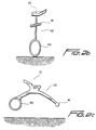
- Figs. 2b and 2c are schematic diagrams of implementations of the embodiment of Fig. 1 in which the transmitter and receiver are mounted on a single moveable structure.
- Fig. 3 is a schematic diagram of a particularly preferred implementation of the embodiment of Fig. 1, with conductive injection of the waveform.
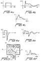
- Fig. 4a is a waveform diagram of a suitable injected waveform.
- Figs. 4b and 4c are respective time and frequency domain waveform diagrams for the re-radiated signal corresponding to the injected signal of Fig. 4a.
- Fig. 4d is a waveform diagram of an injected waveform made up of a square wave with an inductive kick.
- Figs. 4e and 4f are respective time and frequency domain waveform diagrams for the re-radiated signal corresponding to the injected signal of Fig. 4d.
- Fig. 5 is a plan view of a display that may be used in connection with the system of Fig. 1.
- Fig. 6 is a flowchart illustrating the principal steps of a method of locating and identifying a conductor according to the principles of the invention.
- a system for locating and identifying a conductor includes a waveform generator 1 for generating a time-duration limited waveform having relatively sharp discontinuities that are subject to distortion so that changes in the shape of the waveform can be easily detected.
- the generated waveform may be conductively coupled directly to the conductor whose position and identity are to be established at a location remote from the point of injection, or the waveform may be inductively coupled to the conductor, using any of a variety of well-known coupling methods or means.
- direct coupling may be achieved by a clamp 2, an electrical connector, or any similar electrical contact-establishing device, while inductive coupling may be achieved either by an inductor 3 placed around the conductor or by means of electromagnetic signals transmitted by an antenna 4.
- inductive coupling the power of the injected waveform must be sufficient to penetrate insulators surrounding the conductor.
- the signal receiver preferably includes antennas 5 connected to amplifiers 6 and analog-to-digital converters 7.
- antennas 5 connected to amplifiers 6 and analog-to-digital converters 7.
- the number and configuration of the receivers may be varied in numerous ways without departing from the scope of the invention, and that the signals may be processed in analog form rather than digitally.
- the illustrated arrangement of antenna, amplifiers, and analog-to-digital converters is intended to be exemplary in nature, and is not intended to limit the invention so long as the antennas have sufficient bandwidth and sensitivity to detect signals radiated from the conductors of interest in response to the injected waveform.
- the converted digital signals are supplied to a digital signal processor 9 for analysis and/or display on display screen 10.
- the analysis seeks to compare the injected waveform with the received waveform to measure the distortion. This can be accomplished either by a complete spectral analysis, or by analysis of received pulse parameters in the time domain, depending on the types of conductors sought. Alternatively, the waveform may simply be displayed for further analysis by the operator of the receiver.
- Fig. 2 which represents one possible antenna configuration
- three broadband antennas are used to receive distorted waveform radiated by the conductor.
- Two of the antennas 20 and 21 are situated in the same horizontal plane to permit the horizontal position of the conductor 22 to be determined.
- the sensor closest to the hidden conductor will generally receive the highest intensity signal, and thus the horizontal position can be determined by simply moving the receiver unit until the signals are equal.
- the depth of the conductor can then be determined by signal decay based on the intensity of the signal received from a third antenna 23 positioned vertically above a midpoint between the first two antennas 20 and 21.
- Fig. 3 illustrates the manner in which the sensors may be integrated with a display in the receiver unit.
- the signal generator 1 is connected to the hidden conductor 22 by direct connection at an above-ground access point 24, although those skilled in the art will appreciate that the system may also utilize inductive coupling as described above.
- the time-duration limited injected waveform may conveniently be in the form of a square wave, as illustrated in Fig. 4a, since the square wave is the simplest abruptly discontinuous signal to produce and evaluate.
- the time-duration limited injected waveform may be in the form of a square wave with an inductive kick or flyback, as shown in Fig. 4d, a sawtooth wave, or any other abruptly discontinuous waves could be substituted.
- FIG. 4b A typical distorted waveform corresponding to the square wave of Fig. 4a applied to a telephone cable is shown in Fig. 4b, and a corresponding Fourier transform of the distorted waveform illustrated in Fig. 4b is shown in Fig. 4c.
- the substantial utility response that occurs after the transmit pulse is over has the advantage of permitting the receiver to be placed very close to the transmitter.
- the transmitter and receiver may even be placed on the same moveable platform.
- the transmitter and receiver are respectively represented by a transmitter coil 40 and a receiver coil 41, which are mounted or attached to a housing structure 42 that also includes or supports the display unit 10.
- a suitable display 10 is illustrated in Fig. 5. It includes a left-right indicator 30 that shows the relative signal strength received by the left and right antennas or sensors based on a comparison of the left and right antenna or sensor signals, a display 31 of the received waveform, and a cursor 32 for selecting portions of the waveform most likely to be indicative of conductor-induced distortion for a particular conductor while minimizing interference from adjacent conductors.
- a cursor position control 33 enables the movement of the cursor by the operator.
- the display could include a textual display of calculated signal parameters, a display of predetermined waveforms to enable pattern matching, an identification of the type of conductor deduced from an analysis of the received waveform, a GPS indicator to show the exact geographic location of the conductor, and so forth.
Landscapes
- Physics & Mathematics (AREA)
- Engineering & Computer Science (AREA)
- Remote Sensing (AREA)
- Life Sciences & Earth Sciences (AREA)
- Electromagnetism (AREA)
- Environmental & Geological Engineering (AREA)
- Geology (AREA)
- General Life Sciences & Earth Sciences (AREA)
- General Physics & Mathematics (AREA)
- Geophysics (AREA)
- Geophysics And Detection Of Objects (AREA)
- Length-Measuring Devices Using Wave Or Particle Radiation (AREA)
Applications Claiming Priority (2)
| Application Number | Priority Date | Filing Date | Title |
|---|---|---|---|
| US984755 | 2001-10-31 | ||
| US09/984,755 US6529006B1 (en) | 2001-10-31 | 2001-10-31 | Method and apparatus for resolving the position and identity of buried conductive bodies |
Publications (2)
| Publication Number | Publication Date |
|---|---|
| EP1308753A2 true EP1308753A2 (fr) | 2003-05-07 |
| EP1308753A3 EP1308753A3 (fr) | 2006-07-05 |
Family
ID=25530833
Family Applications (1)
| Application Number | Title | Priority Date | Filing Date |
|---|---|---|---|
| EP02023060A Withdrawn EP1308753A3 (fr) | 2001-10-31 | 2002-10-16 | Procédé et dispositif destiné à résoudre la position et l'identité de corps conducteurs souterrains |
Country Status (2)
| Country | Link |
|---|---|
| US (1) | US6529006B1 (fr) |
| EP (1) | EP1308753A3 (fr) |
Families Citing this family (27)
| Publication number | Priority date | Publication date | Assignee | Title |
|---|---|---|---|---|
| US6624626B2 (en) * | 1999-11-01 | 2003-09-23 | Polhemus Inc. | Method and apparatus for electromagnetic position and orientation tracking with distortion compensation employing modulated signal |
| US6815953B1 (en) * | 2002-07-03 | 2004-11-09 | Metrotech Corporation | Detecting field distortion in underground line location |
| US20040070535A1 (en) * | 2002-10-09 | 2004-04-15 | Olsson Mark S. | Single and multi-trace omnidirectional sonde and line locators and transmitter used therewith |
| US7062414B2 (en) * | 2003-07-18 | 2006-06-13 | Metrotech Corporation | Method and apparatus for digital detection of electromagnetic signal strength and signal direction in metallic pipes and cables |
| JP3746283B2 (ja) * | 2003-09-22 | 2006-02-15 | エヌ・ティ・ティ・インフラネット株式会社 | 連続ケーブル位置探査装置、連続ケーブル位置探査方法、及び連続ケーブル位置探査プログラム |
| US7113124B2 (en) * | 2003-11-25 | 2006-09-26 | Metrotech Corporation, Inc. | Centerline and depth locating method for non-metallic buried utility lines |
| US7834801B2 (en) * | 2003-11-25 | 2010-11-16 | Metrotech Corporation, Inc. | Sensor fusion for model-based detection in pipe and cable locator systems |
| US7308911B2 (en) * | 2004-08-26 | 2007-12-18 | Kuriyama Of American, Inc. | Electronically detectable high-pressure hose and method of determining the location of the hose |
| GB0505089D0 (en) * | 2005-03-11 | 2005-04-20 | Glaxo Group Ltd | System and methods for detecting environmental conditions |
| US7151375B2 (en) | 2005-04-13 | 2006-12-19 | Marlin Technology, Inc. | Distinguishing false signals in cable locating |
| US7622931B2 (en) * | 2005-10-03 | 2009-11-24 | University Of Utah Research Foundation | Non-contact reflectometry system and method |
| TWI269866B (en) * | 2005-10-07 | 2007-01-01 | Ind Tech Res Inst | Magnetic position finder of dynamic mechanism and pipeline positioning method |
| WO2007106388A2 (fr) * | 2006-03-10 | 2007-09-20 | Metrotech Corporation | Système de localisation et de surveillance de longues lignes |
| US7449892B2 (en) * | 2006-06-02 | 2008-11-11 | Cal-Tek 2000, Inc. | Stray voltage detecting |
| US7557559B1 (en) * | 2006-06-19 | 2009-07-07 | Seektech, Inc. | Compact line illuminator for locating buried pipes and cables |
| US8366690B2 (en) | 2006-09-19 | 2013-02-05 | Kci Licensing, Inc. | System and method for determining a fill status of a canister of fluid in a reduced pressure treatment system |
| TW200821001A (en) | 2006-09-19 | 2008-05-16 | Kci Licensing Inc | Reduced pressure treatment system having blockage clearing and dual-zone pressure protection capabilities |
| US8061360B2 (en) * | 2006-09-19 | 2011-11-22 | Kci Licensing, Inc. | System and method for locating fluid leaks at a drape of a reduced pressure delivery system |
| US8600478B2 (en) | 2007-02-19 | 2013-12-03 | Medtronic Navigation, Inc. | Automatic identification of instruments used with a surgical navigation system |
| US8233963B2 (en) | 2007-02-19 | 2012-07-31 | Medtronic Navigation, Inc. | Automatic identification of tracked surgical devices using an electromagnetic localization system |
| US7710118B2 (en) * | 2007-08-13 | 2010-05-04 | David Emery | Resonant pulse induction metal detector that transmits energy from high voltage flyback pulses |
| US7671576B2 (en) * | 2008-03-06 | 2010-03-02 | Zircon Corporation | Ratiometric AC wire tracer |
| US20130003501A1 (en) * | 2011-06-30 | 2013-01-03 | Henry Palomino Marquez | Methods and apparatus for locating hidden or buried non-conductive pipes and leaks therefrom |
| US10094947B2 (en) * | 2015-10-07 | 2018-10-09 | Metrotech Corporation | System and method for locating underground lines using antenna and positioning information |
| JP7269860B2 (ja) * | 2019-10-09 | 2023-05-09 | 東京瓦斯株式会社 | 埋設物探査システム |
| JP7269859B2 (ja) * | 2019-10-09 | 2023-05-09 | 東京瓦斯株式会社 | 埋設物探査システム及び埋設物探査方法 |
| US20220342106A1 (en) * | 2021-04-27 | 2022-10-27 | The Charles Machine Works, Inc. | Twin coaxial left/right antenna configuration |
Family Cites Families (30)
| Publication number | Priority date | Publication date | Assignee | Title |
|---|---|---|---|---|
| US3418572A (en) | 1966-02-11 | 1968-12-24 | Thomas G. Humphreys Jr. | Apparatus including variable frequency indicating means for locating and tracing conductive structures |
| US3806795A (en) * | 1972-01-03 | 1974-04-23 | Geophysical Survey Sys Inc | Geophysical surveying system employing electromagnetic impulses |
| US3991393A (en) * | 1975-06-02 | 1976-11-09 | General Electric Company | Servomechanism control cylinder |
| GB2041531B (en) | 1979-01-29 | 1983-09-14 | British Gas Corp | Detecting inaccessible objects |
| EP0024183A1 (fr) | 1979-08-18 | 1981-02-25 | Geodate Limited | Procédé pour détecter des défauts dans le manchon protecteur électriquement conducteur d'un câble |
| US4325027A (en) * | 1979-11-28 | 1982-04-13 | Compass Electronics | Metal detector for locating objects with full sensitivity in the presence of distributed mineral material |
| US4427942A (en) | 1980-04-29 | 1984-01-24 | Electrolocation Limited | Concealed electrical conductor detecting system |
| US4520317A (en) | 1980-07-31 | 1985-05-28 | Metrotech, Inc. | Apparatus including a pair of automatic gain controlled amplifiers for determining the lateral direction to a concealed conductive object |
| US4387340A (en) | 1980-07-31 | 1983-06-07 | Metrotech, Inc. | Apparatus for determining the distance to a concealed conductive object which is radiating an alternating current signal |
| US4506210A (en) | 1982-02-18 | 1985-03-19 | The United States Of America As Represented By The Secretary Of The Army | Method for identifying cable conductors using two signals at different frequencies |
| US4639674A (en) | 1983-04-11 | 1987-01-27 | Schonstedt Instrument Company | Apparatus and method employing extraneous field compensation for locating current-carrying objects |
| US4542344A (en) | 1983-09-02 | 1985-09-17 | Corrosion Logging Service International | Detecting buried pipeline depth and location with electromagnetic triangulation |
| JPH0619471B2 (ja) * | 1984-03-30 | 1994-03-16 | 株式会社日立製作所 | 地中物体の識別方法および装置 |
| US4843324A (en) | 1985-12-09 | 1989-06-27 | R. Donald Plosser | Apparatus for determining the location and distance to a concealed conductive structure |
| DE3785025T2 (de) * | 1986-10-30 | 1993-10-21 | Nippon Telegraph & Telephone | Verfahren zum nachweis eines gegenstandes und vorrichtung dazu. |
| US4868504A (en) * | 1987-02-09 | 1989-09-19 | Flr, Inc. | Apparatus and method for locating metal objects and minerals in the ground with return of energy from transmitter coil to power supply |
| US4818944A (en) | 1987-05-06 | 1989-04-04 | Schonstedt Instrument Company | Magnetic locating and tracing system and method using dual-antenna transmitter to distinguish between concealed adjacent objects |
| US5093622A (en) | 1989-03-17 | 1992-03-03 | Minnesota Mining And Manufacturing Company | Method and apparatus for determining direction to and position of an underground conductor |
| US5361029A (en) | 1990-06-18 | 1994-11-01 | The Charles Machine Works, Inc. | System for locating multiple concealed underground objects |
| US5640092A (en) | 1990-09-27 | 1997-06-17 | Motazed; Behnam | Electromagnetic pipe mapper for accurate location and depth determination |
| DE4103234C2 (de) | 1991-02-02 | 1994-07-14 | Beha C Gmbh | Verfahren und Leitungssucher zum berührungslosen Suchen und Identifizieren von elektrischen Leitungen |
| US5365163A (en) | 1992-09-29 | 1994-11-15 | Minnesota Mining And Manufacturing Company | Sensor array for circuit tracer |
| US5471143A (en) | 1993-01-29 | 1995-11-28 | Minnesota Mining And Manufacturing Co. | Apparatus for locating buried conductors using phase-shifted signals |
| US5754049A (en) | 1993-02-17 | 1998-05-19 | Howell; Mark Ian | Method and apparatus for locating buried conductors in the presence of plural conductors |
| US5457394A (en) * | 1993-04-12 | 1995-10-10 | The Regents Of The University Of California | Impulse radar studfinder |
| JPH10206390A (ja) * | 1997-01-22 | 1998-08-07 | Kawasaki Steel Corp | 埋設鋼管被覆損傷探査方法 |
| GB9704729D0 (en) * | 1997-03-07 | 1997-04-23 | Radiodetection Ltd | Locator |
| US6140819A (en) | 1998-05-26 | 2000-10-31 | Heath Consultants, Inc. | Continuous-depth-indicating underground pipe and cable locator |
| US6215888B1 (en) | 1998-06-10 | 2001-04-10 | At&T Corp. | Cable location method and apparatus using modeling data |
| US6211807B1 (en) | 1999-05-26 | 2001-04-03 | Geometrics | System using spread spectrum modulation for locating underground objects |
-
2001
- 2001-10-31 US US09/984,755 patent/US6529006B1/en not_active Expired - Lifetime
-
2002
- 2002-10-16 EP EP02023060A patent/EP1308753A3/fr not_active Withdrawn
Also Published As
| Publication number | Publication date |
|---|---|
| EP1308753A3 (fr) | 2006-07-05 |
| US6529006B1 (en) | 2003-03-04 |
Similar Documents
| Publication | Publication Date | Title |
|---|---|---|
| US6529006B1 (en) | Method and apparatus for resolving the position and identity of buried conductive bodies | |
| US5640092A (en) | Electromagnetic pipe mapper for accurate location and depth determination | |
| US5828219A (en) | Method of detecting faults in the insulation layer of an insulated concealed conductor | |
| KR102110692B1 (ko) | 심부 지질, 황화물 광석체 자원 탐지 방법 | |
| CA2205544C (fr) | Procede et appareil de reperage des cables ou tuyaux d'alimentation publique en courant electrique | |
| US6667709B1 (en) | Method and apparatus for detecting leaks in buried pipes by using a selected combination of geophysical instruments | |
| US4818944A (en) | Magnetic locating and tracing system and method using dual-antenna transmitter to distinguish between concealed adjacent objects | |
| AU2006309416B2 (en) | A method for hydrocarbon reservoir mapping and apparatus for use when performing the method | |
| US7277806B2 (en) | Method for removing air wave effect from offshore frequency domain controlled-source electromagnetic data | |
| US20020163346A1 (en) | Detector apparatus and method | |
| EP0995134B1 (fr) | Localisation des conducteurs dissimules | |
| US5798644A (en) | Method and apparatus for locating buried conveyances using locating & confirmation signals with an array of sensors | |
| WO1997012262A9 (fr) | Procede et appareil de reperage des cables ou tuyaux d'alimentation publique en courant electrique | |
| CA2178315A1 (fr) | Procede et appareil de detection d'hydrocarbures par l'intermediaire de courants de foucault induits par des ondes rectangulaires de grande amplitude et de longue duree | |
| JPH11514431A (ja) | 埋設ケーブルの識別 | |
| US6525539B2 (en) | Apparatus and method for locating subsurface objects in conductive soils by measurements of magnetic fields by induced currents with an array of multiple receivers | |
| EP0685078A1 (fr) | Localisaton de conducteurs enterres | |
| US20150369910A1 (en) | Electromagnetic pulse device | |
| KR100399984B1 (ko) | 전자 지하탐사방법 및 지하탐사시스템 | |
| CN100337126C (zh) | 金属管线探测中判断跟踪正误和鉴别管线的方法及装置 | |
| KR101575739B1 (ko) | 지하매설물 관리 시스템 및 방법 | |
| US20110012600A1 (en) | Electromagnetic antenna and method of use for detecting objects | |
| US7808226B1 (en) | Line tracing method and apparatus utilizing non-linear junction detecting locator probe | |
| CZ20031703A3 (cs) | Detekční a identifikační systém pro opticky neviditelné objekty s kódovacím zařízením | |
| CN207908708U (zh) | 导线探测仪 |
Legal Events
| Date | Code | Title | Description |
|---|---|---|---|
| PUAI | Public reference made under article 153(3) epc to a published international application that has entered the european phase |
Free format text: ORIGINAL CODE: 0009012 |
|
| AK | Designated contracting states |
Designated state(s): AT BE BG CH CY CZ DE DK EE ES FI FR GB GR IE IT LI LU MC NL PT SE SK TR |
|
| AX | Request for extension of the european patent |
Extension state: AL LT LV MK RO SI |
|
| PUAL | Search report despatched |
Free format text: ORIGINAL CODE: 0009013 |
|
| AK | Designated contracting states |
Kind code of ref document: A3 Designated state(s): AT BE BG CH CY CZ DE DK EE ES FI FR GB GR IE IT LI LU MC NL PT SE SK TR |
|
| AX | Request for extension of the european patent |
Extension state: AL LT LV MK RO SI |
|
| RIC1 | Information provided on ipc code assigned before grant |
Ipc: G01V 3/12 20060101ALI20060531BHEP Ipc: G01V 3/10 20060101AFI20030205BHEP |
|
| 17P | Request for examination filed |
Effective date: 20061228 |
|
| AKX | Designation fees paid |
Designated state(s): AT BE BG CH CY CZ DE DK EE ES FI FR GB GR IE IT LI LU MC NL PT SE SK TR |
|
| 17Q | First examination report despatched |
Effective date: 20090129 |
|
| STAA | Information on the status of an ep patent application or granted ep patent |
Free format text: STATUS: THE APPLICATION IS DEEMED TO BE WITHDRAWN |
|
| 18D | Application deemed to be withdrawn |
Effective date: 20090609 |