EP1309064A2 - Verfahren zur Betreibssteuerung einer elektrischen Energiespeicherquelle, insbesondere eines Superkondesatorse - Google Patents
Verfahren zur Betreibssteuerung einer elektrischen Energiespeicherquelle, insbesondere eines Superkondesatorse Download PDFInfo
- Publication number
- EP1309064A2 EP1309064A2 EP02292654A EP02292654A EP1309064A2 EP 1309064 A2 EP1309064 A2 EP 1309064A2 EP 02292654 A EP02292654 A EP 02292654A EP 02292654 A EP02292654 A EP 02292654A EP 1309064 A2 EP1309064 A2 EP 1309064A2
- Authority
- EP
- European Patent Office
- Prior art keywords
- source
- electrical
- battery
- temperature
- functional unit
- Prior art date
- Legal status (The legal status is an assumption and is not a legal conclusion. Google has not performed a legal analysis and makes no representation as to the accuracy of the status listed.)
- Withdrawn
Links
Images

Classifications
-
- F—MECHANICAL ENGINEERING; LIGHTING; HEATING; WEAPONS; BLASTING
- F02—COMBUSTION ENGINES; HOT-GAS OR COMBUSTION-PRODUCT ENGINE PLANTS
- F02N—STARTING OF COMBUSTION ENGINES; STARTING AIDS FOR SUCH ENGINES, NOT OTHERWISE PROVIDED FOR
- F02N11/00—Starting of engines by means of electric motors
- F02N11/08—Circuits specially adapted for starting of engines
- F02N11/0862—Circuits specially adapted for starting of engines characterised by the electrical power supply means, e.g. battery
- F02N11/0866—Circuits specially adapted for starting of engines characterised by the electrical power supply means, e.g. battery comprising several power sources, e.g. battery and capacitor or two batteries
-
- H—ELECTRICITY
- H02—GENERATION; CONVERSION OR DISTRIBUTION OF ELECTRIC POWER
- H02J—ELECTRIC POWER NETWORKS; CIRCUIT ARRANGEMENTS OR SYSTEMS FOR SUPPLYING OR DISTRIBUTING ELECTRIC POWER; SYSTEMS FOR STORING ELECTRIC ENERGY
- H02J1/00—Circuit arrangements for DC mains or DC distribution networks
- H02J1/08—Three-wire DC power distribution systems; Systems having more than three wires
- H02J1/082—DC supplies with two or more different DC voltage levels
-
- H—ELECTRICITY
- H02—GENERATION; CONVERSION OR DISTRIBUTION OF ELECTRIC POWER
- H02J—ELECTRIC POWER NETWORKS; CIRCUIT ARRANGEMENTS OR SYSTEMS FOR SUPPLYING OR DISTRIBUTING ELECTRIC POWER; SYSTEMS FOR STORING ELECTRIC ENERGY
- H02J7/00—Circuit arrangements for charging or discharging batteries or for supplying loads from batteries
- H02J7/14—Circuit arrangements for charging or discharging batteries or for supplying loads from batteries for charging batteries from dynamo-electric generators driven at varying speed, e.g. on vehicle
- H02J7/1423—Circuit arrangements for charging or discharging batteries or for supplying loads from batteries for charging batteries from dynamo-electric generators driven at varying speed, e.g. on vehicle with multiple batteries
-
- F—MECHANICAL ENGINEERING; LIGHTING; HEATING; WEAPONS; BLASTING
- F02—COMBUSTION ENGINES; HOT-GAS OR COMBUSTION-PRODUCT ENGINE PLANTS
- F02D—CONTROLLING COMBUSTION ENGINES
- F02D2400/00—Control systems adapted for specific engine types; Special features of engine control systems not otherwise provided for; Power supply, connectors or cabling for engine control systems
- F02D2400/16—Adaptation of engine control systems to a different battery voltages, e.g. for using high voltage batteries
-
- F—MECHANICAL ENGINEERING; LIGHTING; HEATING; WEAPONS; BLASTING
- F02—COMBUSTION ENGINES; HOT-GAS OR COMBUSTION-PRODUCT ENGINE PLANTS
- F02N—STARTING OF COMBUSTION ENGINES; STARTING AIDS FOR SUCH ENGINES, NOT OTHERWISE PROVIDED FOR
- F02N11/00—Starting of engines by means of electric motors
- F02N11/08—Circuits specially adapted for starting of engines
- F02N2011/0881—Components of the circuit not provided for by previous groups
- F02N2011/0885—Capacitors, e.g. for additional power supply
-
- F—MECHANICAL ENGINEERING; LIGHTING; HEATING; WEAPONS; BLASTING
- F02—COMBUSTION ENGINES; HOT-GAS OR COMBUSTION-PRODUCT ENGINE PLANTS
- F02N—STARTING OF COMBUSTION ENGINES; STARTING AIDS FOR SUCH ENGINES, NOT OTHERWISE PROVIDED FOR
- F02N11/00—Starting of engines by means of electric motors
- F02N11/08—Circuits specially adapted for starting of engines
- F02N2011/0881—Components of the circuit not provided for by previous groups
- F02N2011/0888—DC/DC converters
-
- F—MECHANICAL ENGINEERING; LIGHTING; HEATING; WEAPONS; BLASTING
- F02—COMBUSTION ENGINES; HOT-GAS OR COMBUSTION-PRODUCT ENGINE PLANTS
- F02N—STARTING OF COMBUSTION ENGINES; STARTING AIDS FOR SUCH ENGINES, NOT OTHERWISE PROVIDED FOR
- F02N2200/00—Parameters used for control of starting apparatus
- F02N2200/02—Parameters used for control of starting apparatus said parameters being related to the engine
- F02N2200/023—Engine temperature
-
- F—MECHANICAL ENGINEERING; LIGHTING; HEATING; WEAPONS; BLASTING
- F02—COMBUSTION ENGINES; HOT-GAS OR COMBUSTION-PRODUCT ENGINE PLANTS
- F02N—STARTING OF COMBUSTION ENGINES; STARTING AIDS FOR SUCH ENGINES, NOT OTHERWISE PROVIDED FOR
- F02N2200/00—Parameters used for control of starting apparatus
- F02N2200/06—Parameters used for control of starting apparatus said parameters being related to the power supply or driving circuits for the starter
- F02N2200/063—Battery voltage
-
- H—ELECTRICITY
- H02—GENERATION; CONVERSION OR DISTRIBUTION OF ELECTRIC POWER
- H02J—ELECTRIC POWER NETWORKS; CIRCUIT ARRANGEMENTS OR SYSTEMS FOR SUPPLYING OR DISTRIBUTING ELECTRIC POWER; SYSTEMS FOR STORING ELECTRIC ENERGY
- H02J2105/00—Networks for supplying or distributing electric power characterised by their spatial reach or by the load
- H02J2105/30—Networks for supplying or distributing electric power characterised by their spatial reach or by the load the load networks being external to vehicles, i.e. exchanging power with vehicles
- H02J2105/33—Networks for supplying or distributing electric power characterised by their spatial reach or by the load the load networks being external to vehicles, i.e. exchanging power with vehicles exchanging power with road vehicles
-
- H—ELECTRICITY
- H02—GENERATION; CONVERSION OR DISTRIBUTION OF ELECTRIC POWER
- H02J—ELECTRIC POWER NETWORKS; CIRCUIT ARRANGEMENTS OR SYSTEMS FOR SUPPLYING OR DISTRIBUTING ELECTRIC POWER; SYSTEMS FOR STORING ELECTRIC ENERGY
- H02J7/00—Circuit arrangements for charging or discharging batteries or for supplying loads from batteries
- H02J7/34—Parallel operation in networks using both storage and other DC sources, e.g. providing buffering
- H02J7/345—Parallel operation in networks using both storage and other DC sources, e.g. providing buffering using capacitors as storage or buffering devices
-
- Y—GENERAL TAGGING OF NEW TECHNOLOGICAL DEVELOPMENTS; GENERAL TAGGING OF CROSS-SECTIONAL TECHNOLOGIES SPANNING OVER SEVERAL SECTIONS OF THE IPC; TECHNICAL SUBJECTS COVERED BY FORMER USPC CROSS-REFERENCE ART COLLECTIONS [XRACs] AND DIGESTS
- Y02—TECHNOLOGIES OR APPLICATIONS FOR MITIGATION OR ADAPTATION AGAINST CLIMATE CHANGE
- Y02T—CLIMATE CHANGE MITIGATION TECHNOLOGIES RELATED TO TRANSPORTATION
- Y02T10/00—Road transport of goods or passengers
- Y02T10/60—Other road transportation technologies with climate change mitigation effect
- Y02T10/70—Energy storage systems for electromobility, e.g. batteries
Definitions
- the present invention relates to a management method an electrical energy storage source capable of deliver electrical power in a short period of time important to an electric charge intended to activate a functional unit provided that an order predetermined is applied to this functional unit.
- the invention relates to the supply of electrical networks connected to at least two sources of electrical energy storage, one of which must be able to deliver high electrical power for short periods of time to meet demand a large load connected to one of the networks, and the other of which must be able to supply a moderate electrical power for periods of time extended by being connected to the second of the networks.
- the invention is not specifically there limited, it finds a particularly advantageous in automotive technology, networks electric motor vehicles to insure the power supply of large consumers of current, such as for example the starter intended to start the engine with which they are fitted, other charges low power electrics that must remain powered, when the vehicle is stopped with the engine off.
- the on-board network is powered by a dual-voltage system, chosen values of the voltages generally being 12/14 volts in low voltage to ensure power supply and 36/42 Volts at high voltage to ensure that of the loads of power, first of all the starter.
- Dual-voltage on-board networks generally include an electrical energy storage source providing the low voltage, usually the conventional battery, and a other source capable in a short time of delivering high power at high network voltage.
- the sources of the second type are basically the supercapacitors already well known to specialists since some time.
- the alternator When the heat engine of a vehicle turns, the alternator provides the energy and average power required to ensure all requests from the on-board network. Therefore, the two types of storage sources mentioned above have only for the function of ensuring the starting of the heat engine, absorption of power demand irregularities network and maintaining certain electrical functions during occasional stops of the engine (for example during operation with what is known as "stop and go") or again during prolonged abandonments of the vehicle when a few modest consumers ask little power.
- the supercapacitors and also similar storage sources such as Li-ion, Ni-MH or lead power batteries spiral. He also knows that this type of sources, capable to deliver a lot of electrical power in a short time of time, do not pose the same problems of aging than energy supply batteries whose lifespan is determined in particular by cycles of charge / discharge to which their active material is subjected.
- power storage sources like supercapacitors, have a specific power which depends very little on the temperature, at least in the temperature range between -25 ° C and + 65 ° C usually considered in automotive technology.
- the object of the invention is to facilitate sizing storage sources of this type and avoid the need of their oversizing.
- the invention therefore relates to a method for managing the type defined in the preamble which is characterized in that it consists, before activating said functional unit, of determine the temperature and, if said temperature is below a predetermined temperature, to be carried out at least once the operations of connecting said electric charge on said energy storage source electric without applying said predetermined command, then recharging said storage source, said charge then being reconnected and said control applied to said functional unit to make it function.
- the management method according to the invention is described below in the context of a dual network dual-voltage power supply on board a vehicle automotive, it should be noted that it applies in all cases where it is a question of managing the operation of a set of supercapacitors, or a storage source analog electric power, working cooperatively with another energy source allowing, if necessary, recharge the set of supercapacitors, these sources in front in particular ensuring the electrical supply of a unit functional which only becomes operational if a signal of predetermined command is applied to it. So the process according to the invention can be applied in the context of the power supply of devices as varied as laptops, satellites and more.
- the invention can also be applied to a single-voltage power system electric.
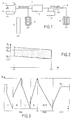
- FIG. 1 a classic dual-voltage power system for a vehicle automobile, system to which the method according to the invention can advantageously be applied. It includes a first network 1 at high voltage, for example at 36/42 Volts which, motor thermal (not shown) of the rotating vehicle, is powered by an alternator 2, mounted in parallel on a set of supercapacitor elements 3 (hereinafter called convenience "super-capacitor"). A starter 4 for the engine is connected to this high-voltage network, as well than other 5 consumers of significant power, such as air conditioning for example.
- the first high-voltage network 1 is connected to a second low voltage network 6, for example 12/14 Volts via a reversible converter 7 capable to transform low voltage into high voltage and vice versa, and also to transmit back and forth from electrical energy from one network to another.
- a reversible converter 7 capable to transform low voltage into high voltage and vice versa, and also to transmit back and forth from electrical energy from one network to another.
- a battery 8 for example lead
- low voltage consumers 9 such as radio, lights and the like.
- the first and second networks 1 and 6 are supplied by alternator 2, when the engine is running.
- the electrical energy storage sources 3 and 8 are then kept charged, it being understood that the battery 8 receives its charge current via the converter 7.
- the vehicle is stopped and the engine thermal is cut, it is essentially the battery 8 which energizes those among consumers 9 who then remain connected to the network.
- This feeding mode can obviously last for example if the vehicle is abandoned for extended periods.
- starter 4 is supplied essentially in power by the supercapacitor 3 of which the charge is maintained, if necessary by drawing energy from battery 8 after conversion in converter 7.
- Figure 2 illustrates the behavior of a supercapacitor when it is subjected to a high demand for power.
- a high power consumer is connected to a supercapacitor charged to the voltage U s1
- the voltage across the latter drops immediately to a voltage U s2 due to the voltage drop in the internal resistance of the supercapacitor.
- the consumer is connected (interval t 2 - t 1 )
- the voltage will fall further due to the pressure drop to a voltage U s3 , the voltage rising to a value U s4 , close to the initial voltage, when the consumer is disconnected.
- the hatched part of the diagram in FIG. 2 corresponds to the energy dissipated in the internal resistance of the supercapacitor. The aging of the supercapacitor gradually increases this amount of dissipated energy.
- starting the engine involves compliance with at least three conditions.
- the network voltage 1 (figure 1) must not drop below a minimum value so that the power other essential consumers during startup can be maintained. It is also appropriate that the supercapacitor can provide enough power to turn the starter and start the engine thermal up to a speed of rotation sufficient for trigger the combustion process. Finally, this power must be supplied for a sufficient time to that this process can start.
- the management method according to the invention uses this phenomenon of reduction of internal resistance so as to avoid a immobilizing failure if a start must be performed under unfavorable temperature conditions and aging of the supercapacitor.
- the management program can be run as subprogramme of the general program presiding over operation of the entire heat engine and / or vehicle (ignition, injection, gearbox etc.) and at this title it can be executed by the central computer (not shown) of the vehicle. Of course, it can also be provided a calculator specially dedicated to the task of managing the electrical system.
- the program according to the invention begins at the step of program S1 of figure 4. At the step of program S2, it is first check if a start is requested. This test is performed until a start to start is observed.
- a test is carried out for check whether the starting conditions noted in the characteristic table match conditions adequate starting. If so, the program authorizes and controls the starting of the engine (not S8) and the program ends in S9.
- test for program step S11 If the test for program step S11 is affirmative, the program enters a processing loop which puts in an essential characteristic of the invention.
- the operations of this processing loop are illustrated graphically in Figure 3.
- the first step of the S12 program in this loop program is to allow the engine to start thermal, but without a large order for the engine operation is given. It can be the temporary deactivation for example of the order injection or ignition. As a result, the engine starts to rotate but does not really start. Under these conditions, the engine imposing a torque important training for the starter, it will constitute a high-power consumer for the supercapacitor 3 which will therefore be discharged with a strong current consumed and a significant reduction in its internal resistance.
- step discharge operation program S12 being continued until the voltage minimum admissible on the supercapacitor 3 or reached, it is immediately followed by an operation of recharge (no S13 program) from battery 8 via converter 7, the load bringing back the voltage across the supercapacitor 3 back to the maximum tension.
- the recharge being completed it is checked during the no S14 program if the temperature and tension are satisfactory with regard to the supercapacitor 3, to start the engine thermal. If not, the program returns to the operation of program step S12 to cause a new launch of the heat engine, from which a high current discharge, further warming of the supercapacitor 3 and therefore a reduction in resistance internal of the latter. After a new recharge according to the no S13 program, the test in S14 is repeated and if this time it turns out to be positive, a start is attempted. In in other words, the starter 4 is connected while the control (injection or ignition) of the engine is assured.
- FIG. 3 shows an example of execution of the method of the invention by the evolution of the voltage U s on the supercapacitor 3 between the maximum value and the minimum admissible value.
- the discharge D is carried out twice and then the recharge R of the supercapacitor 3 (phase PH1) after which the start-up DEM takes place during the phase PH2 followed by a phase PH3 of normal operation of the heat engine started, the voltage across the supercapacitor 3 then reaching its normal operating value U fl (also called "floating voltage" by specialists).
Landscapes
- Engineering & Computer Science (AREA)
- Power Engineering (AREA)
- Chemical & Material Sciences (AREA)
- Combustion & Propulsion (AREA)
- Mechanical Engineering (AREA)
- General Engineering & Computer Science (AREA)
- Charge And Discharge Circuits For Batteries Or The Like (AREA)
Applications Claiming Priority (2)
| Application Number | Priority Date | Filing Date | Title |
|---|---|---|---|
| FR0113890A FR2831726B1 (fr) | 2001-10-26 | 2001-10-26 | Procede de gestion du fonctionnement d'une source de stockage d'energie electrique, notamment d'un supercondensateur |
| FR0113890 | 2001-10-26 |
Publications (2)
| Publication Number | Publication Date |
|---|---|
| EP1309064A2 true EP1309064A2 (de) | 2003-05-07 |
| EP1309064A3 EP1309064A3 (de) | 2008-08-20 |
Family
ID=8868774
Family Applications (1)
| Application Number | Title | Priority Date | Filing Date |
|---|---|---|---|
| EP02292654A Withdrawn EP1309064A3 (de) | 2001-10-26 | 2002-10-25 | Verfahren zur Betreibssteuerung einer elektrischen Energiespeicherquelle, insbesondere eines Superkondesatorse |
Country Status (2)
| Country | Link |
|---|---|
| EP (1) | EP1309064A3 (de) |
| FR (1) | FR2831726B1 (de) |
Cited By (5)
| Publication number | Priority date | Publication date | Assignee | Title |
|---|---|---|---|---|
| WO2006069620A1 (de) * | 2004-12-28 | 2006-07-06 | Volkswagen Aktiengesellschaft | Verfahren und vorrichtung zum optimierten starten eines verbrennungsmotors |
| EP1813806A1 (de) * | 2005-02-02 | 2007-08-01 | Tai-Her Yang | Einspritz- und Zündsystem mit Anlass- und Hilfsbatterie |
| EP1858135A3 (de) * | 2006-05-17 | 2009-06-03 | Hitachi, Ltd. | Im Fahrzeug eingebautes Stromversorgungssystem, im Fahrzeug eingebauter Generator und Generatorsteuerung |
| US8237305B2 (en) | 2008-07-22 | 2012-08-07 | Alexander Kade | Auxiliary electrical power system for vehicular fuel economy improvement |
| CN113567771A (zh) * | 2020-04-29 | 2021-10-29 | 南通江海储能技术有限公司 | 一种锂离子电容器的梯次筛分方法 |
Families Citing this family (3)
| Publication number | Priority date | Publication date | Assignee | Title |
|---|---|---|---|---|
| FR2928789B1 (fr) * | 2008-03-14 | 2011-08-05 | Peugeot Citroen Automobiles Sa | Strategie de gestion d'un stockeur electrique. |
| FR2949864B1 (fr) * | 2009-09-09 | 2011-08-19 | Peugeot Citroen Automobiles Sa | Procede de determination d'un etat de fonctionnement de moyens de stockage d'energie electrique constitues d'au moins un supercondensateur |
| FR2963996B1 (fr) * | 2010-08-19 | 2012-09-21 | Peugeot Citroen Automobiles Sa | Procede de decharge d'un dispositif de stockage d'energie d'un vehicule en mode parking longue duree et vehicule associe |
Family Cites Families (2)
| Publication number | Priority date | Publication date | Assignee | Title |
|---|---|---|---|---|
| US6222341B1 (en) * | 1997-09-17 | 2001-04-24 | Johnson Controls Technology Company | Dual battery charge maintenance system and method |
| US6271648B1 (en) * | 2000-09-27 | 2001-08-07 | Ford Global Tech., Inc. | Method of preconditioning a battery to improve cold temperature starting of a vehicle |
-
2001
- 2001-10-26 FR FR0113890A patent/FR2831726B1/fr not_active Expired - Fee Related
-
2002
- 2002-10-25 EP EP02292654A patent/EP1309064A3/de not_active Withdrawn
Cited By (6)
| Publication number | Priority date | Publication date | Assignee | Title |
|---|---|---|---|---|
| WO2006069620A1 (de) * | 2004-12-28 | 2006-07-06 | Volkswagen Aktiengesellschaft | Verfahren und vorrichtung zum optimierten starten eines verbrennungsmotors |
| US8276559B2 (en) | 2004-12-28 | 2012-10-02 | Volkswagen Ag | Method and device for the optimized starting of an internal combustion engine |
| EP1813806A1 (de) * | 2005-02-02 | 2007-08-01 | Tai-Her Yang | Einspritz- und Zündsystem mit Anlass- und Hilfsbatterie |
| EP1858135A3 (de) * | 2006-05-17 | 2009-06-03 | Hitachi, Ltd. | Im Fahrzeug eingebautes Stromversorgungssystem, im Fahrzeug eingebauter Generator und Generatorsteuerung |
| US8237305B2 (en) | 2008-07-22 | 2012-08-07 | Alexander Kade | Auxiliary electrical power system for vehicular fuel economy improvement |
| CN113567771A (zh) * | 2020-04-29 | 2021-10-29 | 南通江海储能技术有限公司 | 一种锂离子电容器的梯次筛分方法 |
Also Published As
| Publication number | Publication date |
|---|---|
| FR2831726A1 (fr) | 2003-05-02 |
| EP1309064A3 (de) | 2008-08-20 |
| FR2831726B1 (fr) | 2004-01-16 |
Similar Documents
| Publication | Publication Date | Title |
|---|---|---|
| EP2715909B1 (de) | Verfahren zur wiederaufladung eines fahrzeugbatteriepaares mit unterschiedlichen nennspannungen und zugehöriges system | |
| EP2138711B1 (de) | Verfahren zur Steuerung einer Vorrichtung zum Ausschalten und automatischen Neustart eines Verbrennungsmotors eines Fahrzeugs | |
| FR2982316A1 (fr) | Procede de regeneration d'un filtre a particules pour vehicule automobile hybrideprocede de regeneration d'un filtre a particules pour vehicule automobile hybride | |
| EP2089630A1 (de) | Verfahren zur steuerung einer stopp- und automatikneustartvorrichtung für einen verbrennungsmotor | |
| EP1130737B1 (de) | Autonome elektrische Einrichtung, insbesondere für Fahrzeug | |
| EP1309064A2 (de) | Verfahren zur Betreibssteuerung einer elektrischen Energiespeicherquelle, insbesondere eines Superkondesatorse | |
| FR2964511A1 (fr) | Reseau de bord d'un vehicule avec dispositif de maintien en tension comprenant un supercondensateur, vehicule et procede de dechargement d'un supercondensateur | |
| EP2112739B1 (de) | Verfahren zur begrenzung der inneren erwärmung eines super-kondensators | |
| EP2476001A1 (de) | Verfahren zur bestimmung eines betriebszustandes von stromspeichervorrichtungen aus mindestens einem ultrakondensator | |
| FR2991104A1 (fr) | Procede et dispositif pour la desulfatation d'une batterie | |
| EP2552722A1 (de) | Verfahren zur überwachung des ladezustandes einer zusätzlichen energiespeichereinrichtung eines fahrzeuges mit mikrohybridantrieb und system mit dem verfahren | |
| FR2848033A1 (fr) | Systeme et procede d'alimentation electrique a deux tensions pour vehicule. | |
| EP2628234A1 (de) | Verfahren zum aufladen eines superkondensatormoduls für ein kraftfahrzeug und zugehöriges kraftfahrzeug | |
| EP2622206A2 (de) | Verfahren zur handhabung des automatischen stopps und starts einer wärmekraftmaschine eines kraftfahrzeuges und entsprechendes kraftfahrzeug | |
| FR3059956B1 (fr) | Demarrage du moteur thermique d'un vehicule automobile avec une gestion de deux ou plusieurs batteries en cas de besoin critique | |
| EP3746342A1 (de) | System und verfahren zur steuerung der dem stromkreis eines hybridfahrzeugs zugeführten energie und kraftfahrzeug damit | |
| EP2794375B1 (de) | Verfahren zur verwaltung von elektrizität bei einem kraftfahrzeug und kraftfahrzeug mit einem solchen verfahren | |
| FR2928789A1 (fr) | Strategie de gestion d'un stockeur electrique. | |
| WO2008107616A2 (fr) | Procede et systeme de surveillance de l'etat de charge et de conditionnement d'un organe de stockage d'energie electrique d'un vehicule | |
| EP4133567A1 (de) | System zur elektrischen energieversorgung eines kraftfahrzeugs | |
| FR3132955A1 (fr) | Gestion de l’ordonnancement de tests dans un système comprenant deux batteries de servitude | |
| FR3076522A1 (fr) | «systeme de volant de direction chauffant pour vehicule automobile et procede de gestion de ce systeme» | |
| FR3010833A3 (fr) | Batterie pour vehicule hybride |
Legal Events
| Date | Code | Title | Description |
|---|---|---|---|
| PUAI | Public reference made under article 153(3) epc to a published international application that has entered the european phase |
Free format text: ORIGINAL CODE: 0009012 |
|
| AK | Designated contracting states |
Designated state(s): AT BE BG CH CY CZ DE DK EE ES FI FR GB GR IE IT LI LU MC NL PT SE SK TR |
|
| AX | Request for extension of the european patent |
Extension state: AL LT LV MK RO SI |
|
| PUAL | Search report despatched |
Free format text: ORIGINAL CODE: 0009013 |
|
| AK | Designated contracting states |
Kind code of ref document: A3 Designated state(s): AT BE BG CH CY CZ DE DK EE ES FI FR GB GR IE IT LI LU MC NL PT SE SK TR |
|
| AX | Request for extension of the european patent |
Extension state: AL LT LV MK RO SI |
|
| RIC1 | Information provided on ipc code assigned before grant |
Ipc: F02N 11/08 20060101AFI20080716BHEP |
|
| 17P | Request for examination filed |
Effective date: 20090219 |
|
| AKX | Designation fees paid |
Designated state(s): AT BE BG CH CY CZ DE DK EE ES FI FR GB GR IE IT LI LU MC NL PT SE SK TR |
|
| 17Q | First examination report despatched |
Effective date: 20101025 |
|
| GRAP | Despatch of communication of intention to grant a patent |
Free format text: ORIGINAL CODE: EPIDOSNIGR1 |
|
| STAA | Information on the status of an ep patent application or granted ep patent |
Free format text: STATUS: THE APPLICATION HAS BEEN WITHDRAWN |
|
| 18W | Application withdrawn |
Effective date: 20120201 |