EP2715909B1 - Verfahren zur wiederaufladung eines fahrzeugbatteriepaares mit unterschiedlichen nennspannungen und zugehöriges system - Google Patents
Verfahren zur wiederaufladung eines fahrzeugbatteriepaares mit unterschiedlichen nennspannungen und zugehöriges system Download PDFInfo
- Publication number
- EP2715909B1 EP2715909B1 EP12728690.4A EP12728690A EP2715909B1 EP 2715909 B1 EP2715909 B1 EP 2715909B1 EP 12728690 A EP12728690 A EP 12728690A EP 2715909 B1 EP2715909 B1 EP 2715909B1
- Authority
- EP
- European Patent Office
- Prior art keywords
- voltage
- battery
- vehicle
- network
- maximum
- Prior art date
- Legal status (The legal status is an assumption and is not a legal conclusion. Google has not performed a legal analysis and makes no representation as to the accuracy of the status listed.)
- Active
Links
Images

Classifications
-
- B—PERFORMING OPERATIONS; TRANSPORTING
- B60—VEHICLES IN GENERAL
- B60L—PROPULSION OF ELECTRICALLY-PROPELLED VEHICLES; SUPPLYING ELECTRIC POWER FOR AUXILIARY EQUIPMENT OF ELECTRICALLY-PROPELLED VEHICLES; ELECTRODYNAMIC BRAKE SYSTEMS FOR VEHICLES IN GENERAL; MAGNETIC SUSPENSION OR LEVITATION FOR VEHICLES; MONITORING OPERATING VARIABLES OF ELECTRICALLY-PROPELLED VEHICLES; ELECTRIC SAFETY DEVICES FOR ELECTRICALLY-PROPELLED VEHICLES
- B60L58/00—Methods or circuit arrangements for monitoring or controlling batteries or fuel cells, specially adapted for electric vehicles
- B60L58/10—Methods or circuit arrangements for monitoring or controlling batteries or fuel cells, specially adapted for electric vehicles for monitoring or controlling batteries
- B60L58/12—Methods or circuit arrangements for monitoring or controlling batteries or fuel cells, specially adapted for electric vehicles for monitoring or controlling batteries responding to state of charge [SoC]
-
- B—PERFORMING OPERATIONS; TRANSPORTING
- B60—VEHICLES IN GENERAL
- B60L—PROPULSION OF ELECTRICALLY-PROPELLED VEHICLES; SUPPLYING ELECTRIC POWER FOR AUXILIARY EQUIPMENT OF ELECTRICALLY-PROPELLED VEHICLES; ELECTRODYNAMIC BRAKE SYSTEMS FOR VEHICLES IN GENERAL; MAGNETIC SUSPENSION OR LEVITATION FOR VEHICLES; MONITORING OPERATING VARIABLES OF ELECTRICALLY-PROPELLED VEHICLES; ELECTRIC SAFETY DEVICES FOR ELECTRICALLY-PROPELLED VEHICLES
- B60L1/00—Supplying electric power to auxiliary equipment of vehicles
- B60L1/003—Supplying electric power to auxiliary equipment of vehicles to auxiliary motors, e.g. for pumps, compressors
-
- B—PERFORMING OPERATIONS; TRANSPORTING
- B60—VEHICLES IN GENERAL
- B60L—PROPULSION OF ELECTRICALLY-PROPELLED VEHICLES; SUPPLYING ELECTRIC POWER FOR AUXILIARY EQUIPMENT OF ELECTRICALLY-PROPELLED VEHICLES; ELECTRODYNAMIC BRAKE SYSTEMS FOR VEHICLES IN GENERAL; MAGNETIC SUSPENSION OR LEVITATION FOR VEHICLES; MONITORING OPERATING VARIABLES OF ELECTRICALLY-PROPELLED VEHICLES; ELECTRIC SAFETY DEVICES FOR ELECTRICALLY-PROPELLED VEHICLES
- B60L1/00—Supplying electric power to auxiliary equipment of vehicles
- B60L1/02—Supplying electric power to auxiliary equipment of vehicles to electric heating circuits
- B60L1/04—Supplying electric power to auxiliary equipment of vehicles to electric heating circuits fed by the power supply line
- B60L1/06—Supplying electric power to auxiliary equipment of vehicles to electric heating circuits fed by the power supply line using only one supply
- B60L1/08—Methods and devices for control or regulation
-
- B—PERFORMING OPERATIONS; TRANSPORTING
- B60—VEHICLES IN GENERAL
- B60L—PROPULSION OF ELECTRICALLY-PROPELLED VEHICLES; SUPPLYING ELECTRIC POWER FOR AUXILIARY EQUIPMENT OF ELECTRICALLY-PROPELLED VEHICLES; ELECTRODYNAMIC BRAKE SYSTEMS FOR VEHICLES IN GENERAL; MAGNETIC SUSPENSION OR LEVITATION FOR VEHICLES; MONITORING OPERATING VARIABLES OF ELECTRICALLY-PROPELLED VEHICLES; ELECTRIC SAFETY DEVICES FOR ELECTRICALLY-PROPELLED VEHICLES
- B60L50/00—Electric propulsion with power supplied within the vehicle
- B60L50/10—Electric propulsion with power supplied within the vehicle using propulsion power supplied by engine-driven generators, e.g. generators driven by combustion engines
- B60L50/16—Electric propulsion with power supplied within the vehicle using propulsion power supplied by engine-driven generators, e.g. generators driven by combustion engines with provision for separate direct mechanical propulsion
-
- B—PERFORMING OPERATIONS; TRANSPORTING
- B60—VEHICLES IN GENERAL
- B60L—PROPULSION OF ELECTRICALLY-PROPELLED VEHICLES; SUPPLYING ELECTRIC POWER FOR AUXILIARY EQUIPMENT OF ELECTRICALLY-PROPELLED VEHICLES; ELECTRODYNAMIC BRAKE SYSTEMS FOR VEHICLES IN GENERAL; MAGNETIC SUSPENSION OR LEVITATION FOR VEHICLES; MONITORING OPERATING VARIABLES OF ELECTRICALLY-PROPELLED VEHICLES; ELECTRIC SAFETY DEVICES FOR ELECTRICALLY-PROPELLED VEHICLES
- B60L50/00—Electric propulsion with power supplied within the vehicle
- B60L50/50—Electric propulsion with power supplied within the vehicle using propulsion power supplied by batteries or fuel cells
- B60L50/53—Electric propulsion with power supplied within the vehicle using propulsion power supplied by batteries or fuel cells in combination with an external power supply, e.g. from overhead contact lines
-
- B—PERFORMING OPERATIONS; TRANSPORTING
- B60—VEHICLES IN GENERAL
- B60L—PROPULSION OF ELECTRICALLY-PROPELLED VEHICLES; SUPPLYING ELECTRIC POWER FOR AUXILIARY EQUIPMENT OF ELECTRICALLY-PROPELLED VEHICLES; ELECTRODYNAMIC BRAKE SYSTEMS FOR VEHICLES IN GENERAL; MAGNETIC SUSPENSION OR LEVITATION FOR VEHICLES; MONITORING OPERATING VARIABLES OF ELECTRICALLY-PROPELLED VEHICLES; ELECTRIC SAFETY DEVICES FOR ELECTRICALLY-PROPELLED VEHICLES
- B60L58/00—Methods or circuit arrangements for monitoring or controlling batteries or fuel cells, specially adapted for electric vehicles
- B60L58/10—Methods or circuit arrangements for monitoring or controlling batteries or fuel cells, specially adapted for electric vehicles for monitoring or controlling batteries
- B60L58/18—Methods or circuit arrangements for monitoring or controlling batteries or fuel cells, specially adapted for electric vehicles for monitoring or controlling batteries of two or more battery modules
- B60L58/20—Methods or circuit arrangements for monitoring or controlling batteries or fuel cells, specially adapted for electric vehicles for monitoring or controlling batteries of two or more battery modules having different nominal voltages
-
- B—PERFORMING OPERATIONS; TRANSPORTING
- B60—VEHICLES IN GENERAL
- B60L—PROPULSION OF ELECTRICALLY-PROPELLED VEHICLES; SUPPLYING ELECTRIC POWER FOR AUXILIARY EQUIPMENT OF ELECTRICALLY-PROPELLED VEHICLES; ELECTRODYNAMIC BRAKE SYSTEMS FOR VEHICLES IN GENERAL; MAGNETIC SUSPENSION OR LEVITATION FOR VEHICLES; MONITORING OPERATING VARIABLES OF ELECTRICALLY-PROPELLED VEHICLES; ELECTRIC SAFETY DEVICES FOR ELECTRICALLY-PROPELLED VEHICLES
- B60L58/00—Methods or circuit arrangements for monitoring or controlling batteries or fuel cells, specially adapted for electric vehicles
- B60L58/10—Methods or circuit arrangements for monitoring or controlling batteries or fuel cells, specially adapted for electric vehicles for monitoring or controlling batteries
- B60L58/24—Methods or circuit arrangements for monitoring or controlling batteries or fuel cells, specially adapted for electric vehicles for monitoring or controlling batteries for controlling the temperature of batteries
- B60L58/27—Methods or circuit arrangements for monitoring or controlling batteries or fuel cells, specially adapted for electric vehicles for monitoring or controlling batteries for controlling the temperature of batteries by heating
-
- B—PERFORMING OPERATIONS; TRANSPORTING
- B60—VEHICLES IN GENERAL
- B60L—PROPULSION OF ELECTRICALLY-PROPELLED VEHICLES; SUPPLYING ELECTRIC POWER FOR AUXILIARY EQUIPMENT OF ELECTRICALLY-PROPELLED VEHICLES; ELECTRODYNAMIC BRAKE SYSTEMS FOR VEHICLES IN GENERAL; MAGNETIC SUSPENSION OR LEVITATION FOR VEHICLES; MONITORING OPERATING VARIABLES OF ELECTRICALLY-PROPELLED VEHICLES; ELECTRIC SAFETY DEVICES FOR ELECTRICALLY-PROPELLED VEHICLES
- B60L7/00—Electrodynamic brake systems for vehicles in general
- B60L7/10—Dynamic electric regenerative braking
- B60L7/14—Dynamic electric regenerative braking for vehicles propelled by AC motors
-
- H—ELECTRICITY
- H02—GENERATION; CONVERSION OR DISTRIBUTION OF ELECTRIC POWER
- H02J—ELECTRIC POWER NETWORKS; CIRCUIT ARRANGEMENTS OR SYSTEMS FOR SUPPLYING OR DISTRIBUTING ELECTRIC POWER; SYSTEMS FOR STORING ELECTRIC ENERGY
- H02J7/00—Circuit arrangements for charging or discharging batteries or for supplying loads from batteries
-
- H—ELECTRICITY
- H02—GENERATION; CONVERSION OR DISTRIBUTION OF ELECTRIC POWER
- H02J—ELECTRIC POWER NETWORKS; CIRCUIT ARRANGEMENTS OR SYSTEMS FOR SUPPLYING OR DISTRIBUTING ELECTRIC POWER; SYSTEMS FOR STORING ELECTRIC ENERGY
- H02J7/00—Circuit arrangements for charging or discharging batteries or for supplying loads from batteries
- H02J7/14—Circuit arrangements for charging or discharging batteries or for supplying loads from batteries for charging batteries from dynamo-electric generators driven at varying speed, e.g. on vehicle
-
- H—ELECTRICITY
- H02—GENERATION; CONVERSION OR DISTRIBUTION OF ELECTRIC POWER
- H02J—ELECTRIC POWER NETWORKS; CIRCUIT ARRANGEMENTS OR SYSTEMS FOR SUPPLYING OR DISTRIBUTING ELECTRIC POWER; SYSTEMS FOR STORING ELECTRIC ENERGY
- H02J7/00—Circuit arrangements for charging or discharging batteries or for supplying loads from batteries
- H02J7/14—Circuit arrangements for charging or discharging batteries or for supplying loads from batteries for charging batteries from dynamo-electric generators driven at varying speed, e.g. on vehicle
- H02J7/1423—Circuit arrangements for charging or discharging batteries or for supplying loads from batteries for charging batteries from dynamo-electric generators driven at varying speed, e.g. on vehicle with multiple batteries
-
- H—ELECTRICITY
- H02—GENERATION; CONVERSION OR DISTRIBUTION OF ELECTRIC POWER
- H02J—ELECTRIC POWER NETWORKS; CIRCUIT ARRANGEMENTS OR SYSTEMS FOR SUPPLYING OR DISTRIBUTING ELECTRIC POWER; SYSTEMS FOR STORING ELECTRIC ENERGY
- H02J7/00—Circuit arrangements for charging or discharging batteries or for supplying loads from batteries
- H02J7/50—Circuit arrangements for charging or discharging batteries or for supplying loads from batteries acting upon multiple batteries simultaneously or sequentially
-
- H—ELECTRICITY
- H02—GENERATION; CONVERSION OR DISTRIBUTION OF ELECTRIC POWER
- H02J—ELECTRIC POWER NETWORKS; CIRCUIT ARRANGEMENTS OR SYSTEMS FOR SUPPLYING OR DISTRIBUTING ELECTRIC POWER; SYSTEMS FOR STORING ELECTRIC ENERGY
- H02J7/00—Circuit arrangements for charging or discharging batteries or for supplying loads from batteries
- H02J7/50—Circuit arrangements for charging or discharging batteries or for supplying loads from batteries acting upon multiple batteries simultaneously or sequentially
- H02J7/575—Parallel/serial switching of connection of batteries to charge or load circuit
-
- B—PERFORMING OPERATIONS; TRANSPORTING
- B60—VEHICLES IN GENERAL
- B60L—PROPULSION OF ELECTRICALLY-PROPELLED VEHICLES; SUPPLYING ELECTRIC POWER FOR AUXILIARY EQUIPMENT OF ELECTRICALLY-PROPELLED VEHICLES; ELECTRODYNAMIC BRAKE SYSTEMS FOR VEHICLES IN GENERAL; MAGNETIC SUSPENSION OR LEVITATION FOR VEHICLES; MONITORING OPERATING VARIABLES OF ELECTRICALLY-PROPELLED VEHICLES; ELECTRIC SAFETY DEVICES FOR ELECTRICALLY-PROPELLED VEHICLES
- B60L2210/00—Converter types
- B60L2210/10—DC to DC converters
-
- B—PERFORMING OPERATIONS; TRANSPORTING
- B60—VEHICLES IN GENERAL
- B60L—PROPULSION OF ELECTRICALLY-PROPELLED VEHICLES; SUPPLYING ELECTRIC POWER FOR AUXILIARY EQUIPMENT OF ELECTRICALLY-PROPELLED VEHICLES; ELECTRODYNAMIC BRAKE SYSTEMS FOR VEHICLES IN GENERAL; MAGNETIC SUSPENSION OR LEVITATION FOR VEHICLES; MONITORING OPERATING VARIABLES OF ELECTRICALLY-PROPELLED VEHICLES; ELECTRIC SAFETY DEVICES FOR ELECTRICALLY-PROPELLED VEHICLES
- B60L2210/00—Converter types
- B60L2210/30—AC to DC converters
-
- B—PERFORMING OPERATIONS; TRANSPORTING
- B60—VEHICLES IN GENERAL
- B60L—PROPULSION OF ELECTRICALLY-PROPELLED VEHICLES; SUPPLYING ELECTRIC POWER FOR AUXILIARY EQUIPMENT OF ELECTRICALLY-PROPELLED VEHICLES; ELECTRODYNAMIC BRAKE SYSTEMS FOR VEHICLES IN GENERAL; MAGNETIC SUSPENSION OR LEVITATION FOR VEHICLES; MONITORING OPERATING VARIABLES OF ELECTRICALLY-PROPELLED VEHICLES; ELECTRIC SAFETY DEVICES FOR ELECTRICALLY-PROPELLED VEHICLES
- B60L2210/00—Converter types
- B60L2210/40—DC to AC converters
-
- B—PERFORMING OPERATIONS; TRANSPORTING
- B60—VEHICLES IN GENERAL
- B60L—PROPULSION OF ELECTRICALLY-PROPELLED VEHICLES; SUPPLYING ELECTRIC POWER FOR AUXILIARY EQUIPMENT OF ELECTRICALLY-PROPELLED VEHICLES; ELECTRODYNAMIC BRAKE SYSTEMS FOR VEHICLES IN GENERAL; MAGNETIC SUSPENSION OR LEVITATION FOR VEHICLES; MONITORING OPERATING VARIABLES OF ELECTRICALLY-PROPELLED VEHICLES; ELECTRIC SAFETY DEVICES FOR ELECTRICALLY-PROPELLED VEHICLES
- B60L2240/00—Control parameters of input or output; Target parameters
- B60L2240/40—Drive Train control parameters
- B60L2240/54—Drive Train control parameters related to batteries
- B60L2240/547—Voltage
-
- B—PERFORMING OPERATIONS; TRANSPORTING
- B60—VEHICLES IN GENERAL
- B60L—PROPULSION OF ELECTRICALLY-PROPELLED VEHICLES; SUPPLYING ELECTRIC POWER FOR AUXILIARY EQUIPMENT OF ELECTRICALLY-PROPELLED VEHICLES; ELECTRODYNAMIC BRAKE SYSTEMS FOR VEHICLES IN GENERAL; MAGNETIC SUSPENSION OR LEVITATION FOR VEHICLES; MONITORING OPERATING VARIABLES OF ELECTRICALLY-PROPELLED VEHICLES; ELECTRIC SAFETY DEVICES FOR ELECTRICALLY-PROPELLED VEHICLES
- B60L2240/00—Control parameters of input or output; Target parameters
- B60L2240/80—Time limits
-
- B—PERFORMING OPERATIONS; TRANSPORTING
- B60—VEHICLES IN GENERAL
- B60L—PROPULSION OF ELECTRICALLY-PROPELLED VEHICLES; SUPPLYING ELECTRIC POWER FOR AUXILIARY EQUIPMENT OF ELECTRICALLY-PROPELLED VEHICLES; ELECTRODYNAMIC BRAKE SYSTEMS FOR VEHICLES IN GENERAL; MAGNETIC SUSPENSION OR LEVITATION FOR VEHICLES; MONITORING OPERATING VARIABLES OF ELECTRICALLY-PROPELLED VEHICLES; ELECTRIC SAFETY DEVICES FOR ELECTRICALLY-PROPELLED VEHICLES
- B60L2250/00—Driver interactions
- B60L2250/10—Driver interactions by alarm
-
- Y—GENERAL TAGGING OF NEW TECHNOLOGICAL DEVELOPMENTS; GENERAL TAGGING OF CROSS-SECTIONAL TECHNOLOGIES SPANNING OVER SEVERAL SECTIONS OF THE IPC; TECHNICAL SUBJECTS COVERED BY FORMER USPC CROSS-REFERENCE ART COLLECTIONS [XRACs] AND DIGESTS
- Y02—TECHNOLOGIES OR APPLICATIONS FOR MITIGATION OR ADAPTATION AGAINST CLIMATE CHANGE
- Y02T—CLIMATE CHANGE MITIGATION TECHNOLOGIES RELATED TO TRANSPORTATION
- Y02T10/00—Road transport of goods or passengers
- Y02T10/60—Other road transportation technologies with climate change mitigation effect
- Y02T10/70—Energy storage systems for electromobility, e.g. batteries
-
- Y—GENERAL TAGGING OF NEW TECHNOLOGICAL DEVELOPMENTS; GENERAL TAGGING OF CROSS-SECTIONAL TECHNOLOGIES SPANNING OVER SEVERAL SECTIONS OF THE IPC; TECHNICAL SUBJECTS COVERED BY FORMER USPC CROSS-REFERENCE ART COLLECTIONS [XRACs] AND DIGESTS
- Y02—TECHNOLOGIES OR APPLICATIONS FOR MITIGATION OR ADAPTATION AGAINST CLIMATE CHANGE
- Y02T—CLIMATE CHANGE MITIGATION TECHNOLOGIES RELATED TO TRANSPORTATION
- Y02T10/00—Road transport of goods or passengers
- Y02T10/60—Other road transportation technologies with climate change mitigation effect
- Y02T10/7072—Electromobility specific charging systems or methods for batteries, ultracapacitors, supercapacitors or double-layer capacitors
-
- Y—GENERAL TAGGING OF NEW TECHNOLOGICAL DEVELOPMENTS; GENERAL TAGGING OF CROSS-SECTIONAL TECHNOLOGIES SPANNING OVER SEVERAL SECTIONS OF THE IPC; TECHNICAL SUBJECTS COVERED BY FORMER USPC CROSS-REFERENCE ART COLLECTIONS [XRACs] AND DIGESTS
- Y02—TECHNOLOGIES OR APPLICATIONS FOR MITIGATION OR ADAPTATION AGAINST CLIMATE CHANGE
- Y02T—CLIMATE CHANGE MITIGATION TECHNOLOGIES RELATED TO TRANSPORTATION
- Y02T10/00—Road transport of goods or passengers
- Y02T10/60—Other road transportation technologies with climate change mitigation effect
- Y02T10/72—Electric energy management in electromobility
Definitions
- the invention relates to power supply systems for motor vehicles propelled by a thermal engine or thermal-electric hybrid propulsion, including power supply systems comprising several batteries of different types.
- the use of the lead-acid battery is then preferentially reserved for the starting phases of the vehicle.
- the maximum no-load voltage of the lithium battery must remain relatively close to the maximum empty voltage of the lead-acid battery.
- the maximum energy capacity of the lithium battery is therefore limited.
- Such a system makes it possible to increase the lifetime of the lead-acid battery, but makes it necessary to limit the performance of the lithium batteries used.
- the constant voltage of the alternator must be chosen high enough to simultaneously charge the lead-acid battery and the lithium battery, which induces overconsumption of fuel compared to a system with only a lead-acid battery. .
- the aim of the invention is to propose a system for powering a vehicle comprising two batteries, this system not only making it possible to increase the life of the lead-acid battery, but also to reduce the average fuel consumption of the battery. vehicle.
- the invention is defined by the claims.
- the system further comprises an electronic management unit, configured to impose on the alternator during the rolling of the vehicle, successively at least two different setpoint voltages, namely a low alternator voltage which is strictly greater than the first maximum voltage. empty of the first battery, and a high alternator voltage which is strictly greater than both the minimum voltage of the second battery empty, and the alternator low voltage.
- the alternator may be an alternator system comprising an alternator associated with a DC / DC transformer (direct current / direct current, also called "DC / DC converter"). The alternator can then be controllable itself in tension.
- the setpoint voltage can be controllable by modifying only the setpoint of the DC / DC transformer, the alternator being not controllable in voltage.
- the Setpoint voltage can be controlled by modifying both the voltage delivered by the alternator and the setpoint of the DC / DC transformer.
- the system further comprises a DC / DC voltage transformer adapted to lower the voltage delivered by the second battery to the network.
- the second fully charged operating voltage of the second battery can then be greater than the maximum mains voltage.
- the voltage transformer is bidirectional, and is able to supply the second battery at a voltage greater than the maximum voltage of the network when the alternator delivers a current under the high alternator voltage.
- the first battery may be a lead-acid battery
- the second battery may be a lithium battery, particularly a lithium-ion type battery.
- the second battery can also be a lead-acid battery (conventional or reinforced lead or VRLA according to the English "Valve Regulated Lead Acid Battery") of different characteristics of the first battery.
- the electronic management unit can be configured to open a switch of the second battery when the vehicle is in a parking mode, that is to say the engine stopped, and can be configured, if the voltage of the first battery goes under a first threshold and simultaneously the voltage of the second battery is above a second threshold, to close the switch for a predetermined period before performing the next start of the vehicle. This predetermined period makes it possible to partially recharge the first battery.
- a management method of a motor vehicle equipped with a first battery and a second battery for supplying electrical energy the two batteries having maximum voltages with different voids and being connected to the same alternator and to the same DC electrical network of the vehicle, it imposes a low alternator voltage during the first rolling phases of the vehicle, and imposes a high alternator voltage higher than the alternator low voltage during second vehicle taxiing phases such as regenerative braking phases, less fuel consumers than the first phases.
- the first rolling phases correspond to rolling phases out of deceleration.
- this method can be applied to a motor vehicle where the first battery, the second battery and the alternator are connected in parallel.
- the high alternator voltage is imposed when the vehicle is in a recuperative deceleration phase
- the low alternator voltage is imposed when the vehicle is in an acceleration phase of the engine.
- an alternator intermediate voltage that is strictly greater than the alternator low voltage and less than or equal to the alternator high voltage, when a charge level of the second battery becomes lower than a threshold load, and / or when a certain mode of driving the vehicle other than the deceleration, is detected, and / or if the current delivered by the second battery to the network exceeds a certain threshold.
- the level of the intermediate alternator voltage may be different in the different cases mentioned.
- the second battery with a DC / DC transformer by bringing the voltage across the battery to a value between 15V and 17V during the vehicle's regenerative deceleration phases.
- the system may include solar panels embedded on the vehicle, and connected to the network.
- the system may also include an electrical outlet adapted for recharging the second battery on a network outside the vehicle.
- the second battery may be a refurbished lithium battery that has already been used to provide automotive propulsion energy.
- the second lithium battery is composed of two "worn" modules of a traction battery for an electric vehicle, that is to say whose state of charge is between 70% and 80% of their initial capacity.
- the system according to the invention uses these modules in a voltage range corresponding to a state of charge between 5% and 30% of their initial capacity.
- a switch is placed between the lithium battery and the rest of the system, this switch being open as soon as the state of charge of the battery reaches a state of charge of 5% and is no longer recharged by the system according to the invention, so typically in "parking" mode, that is to say when the vehicle engine is stopped.
- the electronic management unit may be configured to impose a low alternator voltage that is less than or equal to 1.05 times the maximum no-load voltage of the first battery, or even less than 1.035 times the maximum no-load voltage of the first battery. the first battery.
- the alternator low voltage may for example be between 12.8 and 13.5V, and the alternator high voltage can be between 14 and 15V.
- the second battery can be powered by a DC / DC transformer by bringing the voltage across the battery to a value between 15V and 17V during the recuperative deceleration phases of the vehicle.
- a vehicle power supply system 1 comprises an electrical network 2, an alternator 3, a first battery 4, for example a lead-acid battery, a second battery 7, for example a lithium-ion battery, and an electronic management unit 10.
- the second battery 7 is provided with a switch 11 for disconnecting it from the network 2.
- the alternator 3 is able to convert from the mechanical energy taken from a shaft connected to a heat engine (not shown) in electrical energy sent to the electrical network 2.
- the electrical network 2 On the electrical network 2 are disposed electrical consumers 6, such as an air conditioning device, lighting means and heating means.
- the alternator 3 is connected to the terminals of the first battery 4.
- the second battery 7 is connected in parallel to the first battery 4.
- the electrical consumers 6 are connected in parallel to the network 2.
- the network 2 comprises a ground connection 5 on the chassis of the vehicle.
- the network 2 also supplies a starter capable of starting the engine of the vehicle to initiate the first combustion cycle.
- the second battery 7 can be connected to a DC / DC transformer 8 connected in series with the battery 7, so that the voltage across the second battery 7 can be higher than the maximum voltage. network 2.
- energy production means such as solar panels 9 can be connected to the terminals of the second battery 7, which allows the maximum voltage delivered by these solar panels 9 to be higher than the maximum voltage of the network 2.
- the electronic management unit is connected to the alternator 3, to which it is able to impose a variable setpoint voltage and in particular, to which it is capable of imposing two distinct values of setpoints, a first value denoted by Valt_basse and a second value denoted Valt_haute higher than the first value.
- the electronic management unit 10 is also connected to the switch 11 which may be of the mechanical-electromagnetic type, or of the electronic type, for example in the form of a transistor. By opening the switch 11, the electronic management unit 10 can disconnect the second battery 7 from the network, and prevent inadvertent discharge of the second battery 7.
- the first battery especially if the first battery is a lead-acid battery, can be used preferentially at start of the engine of the vehicle, to power a starter.
- the electronic management unit 10 disconnects the second battery 7 (for example a lithium battery, and more precisely lithium-ion type) using the switch 11, as soon as the vehicle is in "parking" mode. In this way, the battery 7 is not discharged.
- the second battery 7 then remains disconnected from the network until the next start of the vehicle engine has been made.
- Lead-acid batteries have excellent cold-start capability, so it is the first lead-acid battery 4 that is used when the vehicle's engine is started.
- Lithium batteries have a better endurance in terms of cycling, and it is therefore the second battery that is used to power the vehicle's network while the vehicle is running.
- the voltage of the network that is to say the measurable voltage between the terminals of the first battery 4
- the voltage of the network is imposed by that of the three elements, among the alternator 3, the first battery 4 and the second battery 7 possibly associated with a DC / DC transformer, which has the highest voltage between its two terminals.
- terminals of each of the elements we mean the two connection points of this element to the network 2.
- the term "voltage across the assembly [second battery 7, DC / DC transformer 8]" is understood to mean the voltage between the two connection points of this assembly, to the network 2.
- the alternator 3 When the alternator 3 does not rotate, for example when the vehicle is started, and the second battery 7 is disconnected by means of the switch 11, it is the first battery 4 which imposes the voltage on the network 2.
- the alternator 3 When the vehicle is running and the alternator 3 is operating, it is chosen to control the voltage setpoint of the alternator 3 above the maximum voltage at no load of the first battery 4. In this way, it is not the first battery 4 which supplies the electrical energy of the circuit 2. Depending on whether the voltage of the alternator 3 is higher or lower than the voltage of the second battery 7, this then will be either the alternator 3 or the second battery 7, or both simultaneously, which will provide the electrical energy of the network 2.
- a second battery 7 is chosen, the maximum empty voltage of which is sufficiently greater than the maximum empty voltage of the first battery 4, so as to be able to alternatively impose two modes of operation.
- the alternator voltage is set to a low value "Low_value”, which is greater than the maximum empty voltage of the first battery "V0max_batt1", itself lower than the maximum voltage tolerated by the Network Vmax_Network.
- the alternator voltage "Valt_basse” is lower than the maximum voltage unladen of the second battery 7 "V0max_batt2".
- the alternator voltage is equal to a high value of alternator voltage "Valt_haute", which is greater than the low alternator voltage, while remaining lower than the maximum voltage tolerated by the network. .
- the alternator 3 when the alternator 3 is regulated to deliver the alternator low voltage, and the second battery 7 is sufficiently charged so that its voltage is greater than the low alternator voltage, it is the second battery 7. 2.
- the operating voltage of the second battery 7 drops to the level of the low alternator voltage, part of the electrical power of the network 2 is supplied. by the second battery 7, and a part of the electrical energy is supplied by the alternator 3.
- the electronic management unit 10 When the electronic management unit 10 imposes the second mode of operation, where it is the alternator high voltage which is imposed, if the unladen voltage of the second battery is lower than the high alternator voltage, it is is then the alternator which supplies the electrical energy to the network and which simultaneously provides energy for recharging the second battery 7.
- the second battery 7 can be recharged during the phases where it is the high alternator voltage is imposed, and can provide the energy to the grid as long as its voltage remains higher than the alternator low voltage, the phases where the electronic management unit 10 imposes the alternator low voltage.
- alternator it is preferable to impose a low alternator voltage just above the maximum empty voltage of the first battery, so that during the phases when the low alternator voltage is imposed, the alternator takes as little as possible of mechanical energy on the motor shaft driven by the engine.
- the alternator thus creates a limited fuel consumption, while ensuring that the first battery is constantly charged to its maximum level.
- the second battery 7 which supplies the battery. electrical energy to the network 2.
- the phases in which the high alternator voltage is imposed in order to recharge the second battery 7 are preferably the low fuel cost taxiing phases, for example the phases of recuperative deceleration, that is to say if the vehicle is in a deceleration mode to use the engine brake, and use some of the mechanical energy of the motor shaft to rotate the alternator.
- the setpoint to the pedal of the vehicle corresponds to a phase of engine deceleration.
- Part of the kinetic energy of braking of the vehicle then serves to recharge the second battery 7. This energy recovered during the braking phases then saves fuel, limiting the alternator voltage imposed during the corresponding driving phases. in the first mode of operation.
- the figure 2 illustrates an example of relative positioning of the different voltage values mentioned previously in the description of the power supply system 1.
- the different levels represented on the figure 2 illustrate the minimum empty voltage of the first battery 4 is V0mini_batt1, the maximum empty voltage of the first battery 4 is V0max_batt1, the minimum voltage unladen V0mini_batt2 of the second battery 7, the maximum voltage unladen V0max_batt2 of the second battery, the alternator low voltage Valt_basse, alternator high voltage Valt_haute and the maximum voltage Vmax_seau network 2 is able to withstand without being damaged.
- the minimum vacuum voltage V0mini_batt1 of the first lead-acid battery is of the order of 12 volts, and is substantially the minimum voltage unladen V0mini_batt2 of the second lithium battery, or is a little lower.
- the maximum unloaded voltage V0max_batt1 of the first lead-acid battery is of the order of 12.8 volts, and the low alternator voltage Valt_basse which is imposed to be just above this maximum voltage when empty is order of 13.2 volts.
- the maximum unloaded voltage V0max_batt2 of the second lithium battery may be of the order of 16.8 volts, and the alternator high voltage Valt_haute of the order of 15 volts in order to remain below the maximum value accepted by network Vmax_seau, which it is of the order of 16 volts.
- the maximum voltage of the second battery is not necessarily greater than the maximum voltage of the network.
- the alternator low voltage should preferably be greater than the maximum no-load voltage of the first battery.
- the alternator low voltage would be very slightly less than the maximum voltage without battery of the first battery, but it would then unnecessarily impose charging and discharging cycles to the first battery by reducing the duration of life of it.
- the maximum voltage of the second battery must necessarily be higher than the maximum no-load voltage of the first battery, so as to be able to define a low voltage value of alternator between these two maximum voltage values when empty of the two batteries.
- the alternator high voltage may be equal to or even greater than the maximum voltage at no load of the second battery, by example if the maximum voltage of the second battery is lower than the maximum voltage tolerated by the network.
- the minimum empty voltage of the second battery must be lower than the high alternator voltage in order to allow at least partial charging of the second battery 7 during the operating phases with the alternator high voltage.
- the second battery 7 can be recharged, in addition during the phases when the alternator rotates to its high voltage value, by additional electrical generating means such as solar panels 9.
- additional electrical generating means such as solar panels 9.
- the maximum voltage at no load of the second battery is lower than the maximum voltage tolerated by the network, or in the case where the system comprises a DC / DC transformer able to lower the voltage delivered by the second battery to a voltage lower than the maximum voltage tolerated by the network, it is possible to also consider recharging the second battery 7 on a network outside the vehicle, for example on a parking area.
- the maximum no-load voltage of the second battery 7, that is to say V0max_batt2, may be lower or higher than the maximum voltage accepted by the network 2. If the maximum voltage at no load of the second battery is greater than the voltage maximum accepted network Vmax_seau, according to a first embodiment, the second battery 7 is operated on only part of its operating range that is to say for example between the low voltage alternator and the high voltage d 'alternator.
- the second battery 7 it is possible to exploit the second battery 7 over a wider range, for example between the low alternator voltage and the maximum empty voltage accepted by the second battery 7, if for example the system is provided with a DC / DC transformer 8, adapted to lower the voltage delivered by the second battery 7 so as to bring it to a value less than or equal to the maximum voltage tolerated by the network.
- the DC / DC transformer is bidirectional, it can even be envisaged to charge the second battery at its maximum voltage unladen by raising the voltage at the terminals of the second battery 7 relative to the high voltage of the alternator during the phases of recuperative deceleration. .
- the alternator low voltage is chosen slightly higher than the maximum empty voltage of the first battery 4.
- the minimum empty voltage of the second battery 7 is preferably lower than the alternator low voltage so that, when the vehicle is in a driving mode where the low alternator voltage is imposed by the unit of electronic management 10, the energy supplied by the alternator automatically comes to supplement the energy provided by the second battery 7 when the voltage thereof is reduced. This prevents the voltage of the second battery 7 can go down to the minimum voltage tolerated V0mini_batt2.
- the minimum empty voltage of the second battery would be greater than the low voltage of the alternator, but it is necessary for such a variant that the electronic management unit 10 imposes a high voltage of the alternator before that the voltage of the second battery 7 does not fall below its minimum value. In any case, the minimum voltage of the second battery 7 must be lower than the high voltage of the alternator.
- the alternator low voltage is preferably lower than the maximum empty voltage of the second battery 7. It is as close as possible, by higher value, to the maximum voltage when empty of the first battery, while keeping a margin of the difference in order to be sure that the low alternator voltage regulated alternator remains above this minimum value V0max_batt1.
- V0max_batt2 is greater than the voltage network maximum Vmax_ network 2, which allows, to choose the values of the alternator low voltage and alternator high voltage, to have the entire voltage range between the maximum voltage of the first battery empty; V0max_battl and the maximum voltage accepted by the network Vmax_network.
- a network 2 of the vehicle whose maximum acceptable voltage is of the order of 15 to 16 volts, and that a lead battery is used as the first battery 4, of which the maximum vacuum voltage is about 12.8 volts, and a lithium-ion battery for the second battery 7, for example a lithium-ion battery reconditioned following use for the electric vehicle propulsion.
- a reconditioned battery has, for example, a maximum no-load voltage of the order of 16.8 volts and an acceptable minimum voltage of not more than 12 volts.
- additional strategies implemented in the electronic management unit 10 may be defined, in order to avoid an excessive discharge of the second battery 7 in the case of figure where the phases of recuperative deceleration are not sufficiently frequent and / or sufficiently prolonged.
- alternator high voltage One or more intermediate voltages can thus be imposed during certain driving phases that may suggest that the next decelerations are distant in time. These driving phases may include highway-type driving modes.
- One or more intermediate voltages may also be imposed for pre-programmed driving modes in the electronic management unit because the operating point of the engine, for these driving modes, corresponds to a lower fuel consumption than for others. driving modes.
- the switching to an alternator alternating voltage can also be conditioned by the simultaneous detection of a given driving mode, and a state of charge less than or equal to a threshold charge state of the second battery 7.
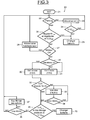
- the figure 3 illustrates an algorithm 1 that can be implemented in the electronic management unit 10 of a power supply system according to the invention.
- the electronic management unit 10 tests, in a step 22, whether the vehicle is in parking mode.
- the electronic management unit 10 disconnects, if it has not already done so, the second battery 7 of the network 2 by means of the switch 11, in a step 23.
- Vmin which may, for example, be equal to the minimum voltage V0mini_batt2 vacuum of the second battery, or be a slightly higher value than this minimum vacuum voltage.
- the electronic management unit 10 displays an alert message warning the driver that he must change the second battery 7, in a step 25. If the voltage is greater than the threshold voltage Vmin, the electronic management unit returns to step 22.
- the electronic management unit 10 tests at a step 26 the health of the second battery 7.
- This health test may for example consist of checking whether the number of cycles of charges and discharges already experienced by the second battery 7 is less than a threshold number Nmax of charges and discharges, if the different cells of the battery are sufficiently balanced, and if the voltage at the terminals of the battery is greater or equal to the threshold voltage Vmin.
- the electronic management unit 10 displays the alert message corresponding to step 25. If the result of the test 26 is positive, the electronic management unit carries out a test 27 to know if the motor thermal vehicle is active. If this is not the case, the electronic management unit 10 sets up a strategy 28 for feeding the network 2 either from the first battery, or from the second battery, or from the two batteries together , then return to step 22.
- the electronic management unit tests at a step 29 if the vehicle is in a mode of recuperative deceleration, that is to say if the vehicle is in a mode deceleration device for using the engine brake, drawing a portion of the mechanical energy from the motor shaft to rotate the alternator.
- a mode of recuperative deceleration that is to say if the vehicle is in a mode deceleration device for using the engine brake, drawing a portion of the mechanical energy from the motor shaft to rotate the alternator.
- the setpoint to the pedal of the vehicle corresponds to a phase of engine deceleration.
- the electronic management unit 10 imposes on the alternator a high alternator voltage, for example 15 volts, in a step 31, and continues to loop on the test 29 and then on the piloting at the alternator high voltage 31, as long as the vehicle is decelerating.
- a high alternator voltage for example 15 volts
- the electronic management unit 10 forces the alternator 3 to operate at the alternator low voltage, for example at 13 volts, at a step 30.
- the electronic management unit 10 tests whether the vehicle and the second battery 7 are in a "forced load” configuration.
- a forced load configuration may, for example, correspond to the case where the voltage at the terminals of the second battery 7 drops below a threshold value V 1 and simultaneously a time counter ⁇ t, which counts the time elapsed since the last deceleration. , passes above a threshold ⁇ t 1 .
- the voltage of the second battery begins to become insufficient, and that the driving mode detected is not a driving mode punctuated by sufficiently frequent decelerations.
- the electronic management unit 10 imposes, at a step 33, a regulation of the alternator 3 at a voltage Valt Mid, for example equal to 14, 5 volts, and continues to impose this mode of charge as long as the battery charge level tested at step 34 has not reached a satisfactory minimum level SOC min .
- This minimum charge level can for example be detected by a decrease of the charging current entering the second battery 7.
- the electronic management unit 10 tests in a step 35 the health of the second battery 7, for example by checking that the temperature of the battery battery does not exceed a maximum temperature T max , verifying that the level of balancing between the different cells is sufficient, or that this level still allows to rebalance the different cells, and verifying that the voltage V at the terminals of the second battery is greater than the threshold voltage V min .
- step 35 If the level of health detected in step 35 is insufficient, the electronic management unit 10 displays the alert message corresponding to step 25. In the opposite case, the electronic management unit 10 tests at a step 36 if the different cells of the second battery 7 are sufficiently balanced. If this is the case, the electronic management unit returns to the test step 22 to check if the vehicle, meanwhile, is in parking mode.
- the electronic management unit triggers a balancing of the cells in a step 37 and also returns to the step 22.
- the object of the invention is not limited to the embodiments described and can be the subject of many variants, both as regards the arrangement of the various elements of the system 1, the operating algorithms implanted in the electronic management unit 10 and / or the choice of types of batteries or other types of accumulators.
- the low voltage and the high voltage imposed on the terminals of the second battery 7 can be obtained either by regulating the voltage delivered by the alternator at two different levels, or by raising the voltage across the second battery with the aid of a DC / DC transformer.
- the high voltage can also be obtained by raising both the setpoint voltage across alternator and transforming this voltage, using the DC / DC transformer, into an even higher voltage across the second battery.
- the operating algorithm admits a great many variants, especially as regards the succession of different tests to determine what alternator voltage must be imposed at a given time, or in the definition of one or more modes of forced charging.
- These forced charging modes can be set with different Valt Mid alternator voltages depending on the modes. For example, it is possible to define different modes of forced charging according to different conditions of charge level of the second battery and different conditions of the type of running and / or operating point of the engine detected.
- the electric accumulators referred to as the first and second batteries may be electrochemical storage batteries, for example a first lead-acid battery and a second lithium-ion battery. It is also possible to consider using for the second battery other types of lithium batteries than lithium-ion batteries, other batteries of the electrochemical type or one or more supercapacitors.
- the invention can be used for a power system of a propulsion vehicle by a heat engine. It can also be used for a power supply system of an electric hybrid electric propulsion vehicle. In the latter case, it is possible for example to use a lithium battery as the first battery used both for starting the vehicle and for occasional propulsion of the vehicle, and a second supercapacitor type battery to accumulate energy during the phases. deceleration. It is therefore necessary to understand in this application the term "electric storage battery” in the broad sense since it encompasses storage systems of the supercapacitor type.
- the system according to the invention makes it possible to reduce the overall fuel consumption of the vehicle, to extend the life of the first battery, and, in the case where one uses as a second battery a reconditioned lithium battery, reduce the cost and the ecological footprint of the system.
- this third battery consists of modules recovered from an electric vehicle traction battery, has the best performance points of the engine and the alternator to be recharged (for example in deceleration, in the same way as the second battery at lithium), and benefits from a complementary charging system such as a solar panel.
- the first lead battery used for starting the vehicle can be connected to the on-board network via a switch, to further specialize its use: this switch is closed for example only at startup, and on the best performance points of the engine and the alternator when its state of charge is below a certain threshold.
- a switch between firstly a first battery and the onboard network and secondly a second battery and the onboard network allows to use for these two batteries lead batteries identical connected in parallel with the alternator without DC / DC intermediate while assigning them a specific role (starting for one, consumption of the onboard network for the other) and having them recharge at the best points of performance of the engine and the alternator.
Landscapes
- Engineering & Computer Science (AREA)
- Power Engineering (AREA)
- Transportation (AREA)
- Mechanical Engineering (AREA)
- Life Sciences & Earth Sciences (AREA)
- Sustainable Development (AREA)
- Sustainable Energy (AREA)
- Charge And Discharge Circuits For Batteries Or The Like (AREA)
- Control Of Charge By Means Of Generators (AREA)
- Electric Propulsion And Braking For Vehicles (AREA)
- Hybrid Electric Vehicles (AREA)
Claims (8)
- System (1) zur Stromversorgung eines Fahrzeugs, das Folgendes umfasst:- ein Gleichstromnetz (2) mit mindestens einem Strom verbrauchenden Organ (6), das geeignet ist, in einem Bereich von Spannungen versorgt zu werden, der niedriger oder gleich einer maximalen Netzspannung (Vmax_reseau) ist,- eine erste Stromspeicherbatterie (4), die an das Netz (2) angeschlossen ist und eine erste maximale Leerspannung (VOmax_Batt1) aufweist, die niedriger ist als die maximale Netzspannung (Vmax_réseau),- eine zweite Stromspeicherbatterie (7), die an das Netz (2) angeschlossen ist, die eine zweite maximale Leerspannung (V0max_Batt2) aufweist, die höher ist als die maximale Leerspannung der ersten Batterie (V0max_Batt1), und eine akzeptable minimale Leerspannung (V0mini_Batt2), die niedriger ist als die maximale Netzspannung (Vmax_reseau),- einen steuerbaren Wechselstromgenerator (3), der an das Netz (2) angeschlossen und geeignet ist, zu der zweiten Batterie (7) eine elektrische Energie unter einer steuerbaren Sollspannung (Valt_basse, Valt_haute) mit unterschiedlichen Sollwerten zu liefern,
dadurch gekennzeichnet, dass das System außerdem eine elektronische Verwaltungseinheit (10) umfasst, die konfiguriert ist, um dem Wechselstromgenerator (3) beim Fahren des Fahrzeugs nacheinander mindestens zwei unterschiedliche Sollspannungen aufzuerlegen, nämlich eine niedrige Wechselstromgeneratorspannung (Valt_basse), die strikt höher ist als die erste maximale Leerspannung der ersten Batterie (V0max_Batt1), und eine hohe Wechselstromgeneratorspannung (Valt_haute), die strikt sowohl höher als die minimale Leerlaufspannung der zweiten Batterie (V0mini_Batt2) als auch als die niedrige Wechselstromgeneratorspannung (Valt_basse) ist. - System nach Anspruch 1, das außerdem einen Spannungstransformator (8) des Typs Gleichstrom / Gleichstrom umfasst, der geeignet ist, um die von der zweiten Batterie (7) zu dem Netz gelieferte Spannung zu senken, und wobei die zweite maximale Leerspannung (V0max_Batt2) der zweiten Batterie (7) höher ist als die maximale Netzspannung (Vmax_reseau).
- System nach Anspruch 2, bei dem der Spannungstransformator (8) bidirektional und geeignet ist, um die zweite Batterie (7) mit einer Spannung zu versorgen, die höher ist als die maximale Netzspannung (Vmax_reseau), wenn der Wechselstromgenerator (3) einen Strom unter der oberen Wechselstromgeneratorspannung (Valt_haute) abgibt.
- System nach einem der vorhergehenden Ansprüche, bei dem die erste Batterie (4) eine Bleibatterie ist und die zweite Batterie (7) eine Lithiumbatterie ist.
- System nach einem der vorhergehenden Ansprüche, bei dem die elektronische Verwaltungseinheit (10) konfiguriert ist, um einen Schalter (11) der zweiten Batterie (7) zu öffnen, wenn der Motor des Fahrzeugs gestoppt wird, und, falls die Spannung der ersten Batterie (4) unter einen ersten Schwellenwert fällt, und die Spannung der zweiten Batterie gleichzeitig oberhalb eines zweiten Schwellenwerts ist, diesen Schalter (11) während einer vorbestimmten Zeitspanne wieder zu schließen, bevor das nächste Anlassen des Fahrzeugs ausgeführt wird.
- Verfahren zur Verwaltung eines Kraftfahrzeugs, das mit einer ersten Batterie (4) und einer zweiten Batterie (7) zur Stromversorgung ausgestattet ist, wobei die zwei Batterien unterschiedliche maximale Leerlaufspannungen (V0max_Batt1, V0max_Batt2) aufweisen und an ein und denselben Wechselstromgenerator (3) und ein und dasselbe Gleichstromnetz des Fahrzeugs (2) angeschlossen sind, dadurch gekennzeichnet, dass während erster Fahrphasen des Fahrzeugs eine niedrige Wechselstromgeneratorspannung (Valt_basse) angelegt wird und während zweiter Fahrphasen des Fahrzeugs, wie den Nutzbremsungsphasen, die weniger Kraftstoff verbrauchen als die ersten Phasen, eine hohe Wechselstromgeneratorspannung (Valt_haute) angelegt wird, die höher ist als die niedrige Wechselstromgeneratorspannung.
- Verfahren nach Anspruch 6, bei dem die hohe Wechselstromgeneratorspannung (Valt_haute) auferlegt wird, wenn das Fahrzeug in Nutzverlangsamungsphase ist und die niedrige Wechselstromgeneratorspannung (Valt_basse) auferlegt wird, wenn sich das Fahrzeug in einer Beschleunigungsphase des Motors befindet.
- Verfahren nach den Ansprüchen 6 bis 7, bei dem eine Wechselstromgeneratorzwischenspannung (Valt_Mid), die strikt höher ist als die niedrige Wechselstromgeneratorspannung (Valt_basse) und niedriger oder gleich der hohen Wechselstromgeneratorspannung (Valt_haute) auferlegt wird, wenn ein Ladungsniveau der zweiten Batterie (7) niedriger wird als eine Schwellenladung, und/oder wenn ein bestimmter anderer Fahrmodus des Fahrzeugs als die Verlangsamung erfasst wird, und/oder falls der von der zweiten Batterie (7) an das Netz gelieferte Strom einen bestimmten Schwellenwert überschreitet.
Applications Claiming Priority (2)
| Application Number | Priority Date | Filing Date | Title |
|---|---|---|---|
| FR1154468A FR2975839B1 (fr) | 2011-05-23 | 2011-05-23 | Procede de rechargement d'un couple de batteries de vehicule de tensions nominales differentes, et systeme associe |
| PCT/FR2012/051081 WO2012160292A2 (fr) | 2011-05-23 | 2012-05-15 | Procede de rechargement d'un couple de batteries de vehicule de tensions nominales differentes, et systeme associe |
Publications (2)
| Publication Number | Publication Date |
|---|---|
| EP2715909A2 EP2715909A2 (de) | 2014-04-09 |
| EP2715909B1 true EP2715909B1 (de) | 2015-07-01 |
Family
ID=46321115
Family Applications (1)
| Application Number | Title | Priority Date | Filing Date |
|---|---|---|---|
| EP12728690.4A Active EP2715909B1 (de) | 2011-05-23 | 2012-05-15 | Verfahren zur wiederaufladung eines fahrzeugbatteriepaares mit unterschiedlichen nennspannungen und zugehöriges system |
Country Status (6)
| Country | Link |
|---|---|
| US (1) | US9643498B2 (de) |
| EP (1) | EP2715909B1 (de) |
| JP (1) | JP6169564B2 (de) |
| CN (1) | CN103891087B (de) |
| FR (1) | FR2975839B1 (de) |
| WO (1) | WO2012160292A2 (de) |
Families Citing this family (27)
| Publication number | Priority date | Publication date | Assignee | Title |
|---|---|---|---|---|
| US9260068B2 (en) * | 2012-10-29 | 2016-02-16 | Sanyo Electric Co., Ltd. | In-vehicle battery system |
| CN105431976B (zh) * | 2013-07-31 | 2018-08-03 | 约翰逊控制技术公司 | 用于具有两种不同化学成分的蓄电池的半有源结构 |
| US9527401B2 (en) | 2014-01-23 | 2016-12-27 | Johnson Controls Technology Company | Semi-active architectures for batteries having two different chemistries |
| JP5862631B2 (ja) * | 2013-10-08 | 2016-02-16 | トヨタ自動車株式会社 | 蓄電システム |
| US9007015B1 (en) | 2014-07-03 | 2015-04-14 | The Noco Company | Portable vehicle battery jump start apparatus with safety protection |
| US11458851B2 (en) | 2014-07-03 | 2022-10-04 | The Noco Company | Jump starting apparatus |
| US11787297B2 (en) * | 2014-07-03 | 2023-10-17 | The Noco Company | Battery charging device for charging a deeply discharged battery, and battery charging system and method |
| US10320202B2 (en) * | 2014-09-30 | 2019-06-11 | Johnson Controls Technology Company | Battery system bi-stable relay control |
| CN110077342A (zh) * | 2014-09-30 | 2019-08-02 | 株式会社自动网络技术研究所 | 汽车用电源装置 |
| US9969292B2 (en) | 2014-11-14 | 2018-05-15 | Johnson Controls Technology Company | Semi-active partial parallel battery architecture for an automotive vehicle systems and methods |
| DE102015002357A1 (de) * | 2015-02-25 | 2016-08-25 | GM Global Technology Operations LLC (n. d. Ges. d. Staates Delaware) | Kraftfahrzeug-Bordnetz und Batteriebaugruppe dafür |
| AU2016228306A1 (en) * | 2015-10-29 | 2017-05-18 | Dc Solutions Australia Pty Ltd | Apparatus for monitoring and assisting a battery |
| EP3217465A1 (de) * | 2016-03-08 | 2017-09-13 | BOS Balance of Storage Systems AG | System zur speicherung elektrischer energie |
| JP6540565B2 (ja) * | 2016-03-16 | 2019-07-10 | 株式会社オートネットワーク技術研究所 | 車両用電源供給システム、車両用駆動システム |
| US10202043B2 (en) | 2016-04-18 | 2019-02-12 | Ford Global Technologies, Llc | Structure to optimize electricity generation in a vehicle |
| FR3068308B1 (fr) | 2017-06-28 | 2019-07-19 | Airbus Group Sas | Systeme de stockage d’energie electrique d’un vehicule et vehicule adapte a le mettre en œuvre |
| JP6971666B2 (ja) * | 2017-07-11 | 2021-11-24 | ビークルエナジージャパン株式会社 | 複合蓄電システムおよび複合蓄電システムの制御方法 |
| DE102017221825B4 (de) * | 2017-12-04 | 2019-06-27 | Audi Ag | Verfahren zum Steuern einer elektrischen Anlage eines elektrisch antreibbaren Kraftfahrzeugs |
| US20190322193A1 (en) * | 2018-04-19 | 2019-10-24 | Wayne State University | Battery module balancing system of a vehicle and method thereof |
| CN112448628B (zh) * | 2019-09-04 | 2022-07-26 | 广州汽车集团股份有限公司 | 一种发电机控制方法及其系统 |
| US12609550B2 (en) * | 2019-10-09 | 2026-04-21 | The Noco Company | Battery charging device for charging a deeply discharged battery, and battery charging system and method |
| US10900540B1 (en) | 2019-11-01 | 2021-01-26 | Phos Global Energy Solutions, Inc. | Mechanical renewable green energy production |
| US10749372B1 (en) | 2019-11-01 | 2020-08-18 | 3B Energy, Llc | Mechanical renewable green energy production |
| FR3104264B1 (fr) * | 2019-12-06 | 2021-12-17 | Psa Automobiles Sa | Diagnostic d’une batterie basse-tension dans un vehicule electrique |
| FR3109248B1 (fr) | 2020-04-10 | 2022-03-04 | Renault Sas | Système d'alimentation en énergie électrique d'un véhicule automobile |
| JP7469219B2 (ja) * | 2020-12-14 | 2024-04-16 | 本田技研工業株式会社 | 電源システム |
| US20260031416A1 (en) * | 2024-07-26 | 2026-01-29 | Lithium Charging Concepts, Inc. | System for charging a house battery bank from an alternator |
Family Cites Families (14)
| Publication number | Priority date | Publication date | Assignee | Title |
|---|---|---|---|---|
| JPH07507977A (ja) * | 1992-05-08 | 1995-09-07 | フィールド,ブルース エフ. | 電気ハイブリッド車両 |
| DE19645944A1 (de) * | 1996-11-07 | 1998-05-14 | Bosch Gmbh Robert | Steuergerät für ein Bordnetz |
| JP2002112406A (ja) * | 2000-09-29 | 2002-04-12 | Mitsubishi Motors Corp | ハイブリッド電気自動車の制御装置 |
| US20040201365A1 (en) * | 2001-04-05 | 2004-10-14 | Electrovaya Inc. | Energy storage device for loads having variable power rates |
| FR2843842B1 (fr) * | 2002-08-26 | 2007-02-23 | Valeo Equip Electr Moteur | Dispositif de commande d'une machine electrique tournante pour vehicule |
| US7336002B2 (en) * | 2003-02-17 | 2008-02-26 | Denso Corporation | Vehicle power supply system |
| JP4254658B2 (ja) * | 2004-08-23 | 2009-04-15 | 株式会社デンソー | 車載電源システム |
| JP4449940B2 (ja) * | 2006-05-16 | 2010-04-14 | トヨタ自動車株式会社 | 車両用二電源システム |
| US20080084182A1 (en) * | 2006-10-06 | 2008-04-10 | Aai Corporation | Lithium battery system |
| JP2008149894A (ja) * | 2006-12-18 | 2008-07-03 | Denso Corp | 車両用電源装置 |
| CA2643878A1 (en) * | 2008-11-14 | 2010-05-14 | Pierre Caouette | An electronic method of controlling propulsion & regeneration for electric, hybrid-electric and diesel-electric marine crafts |
| JP2011010501A (ja) * | 2009-06-29 | 2011-01-13 | Panasonic Corp | 電源装置 |
| EP2272722B1 (de) * | 2009-07-01 | 2015-04-08 | Denso Corporation | Stromquellenvorrichtung für ein Fahrzeug |
| JP5471083B2 (ja) * | 2009-07-01 | 2014-04-16 | 株式会社デンソー | 車載電源装置 |
-
2011
- 2011-05-23 FR FR1154468A patent/FR2975839B1/fr not_active Expired - Fee Related
-
2012
- 2012-05-15 WO PCT/FR2012/051081 patent/WO2012160292A2/fr not_active Ceased
- 2012-05-15 US US14/119,734 patent/US9643498B2/en not_active Expired - Fee Related
- 2012-05-15 JP JP2014511931A patent/JP6169564B2/ja not_active Expired - Fee Related
- 2012-05-15 CN CN201280035910.2A patent/CN103891087B/zh active Active
- 2012-05-15 EP EP12728690.4A patent/EP2715909B1/de active Active
Also Published As
| Publication number | Publication date |
|---|---|
| CN103891087B (zh) | 2017-03-08 |
| CN103891087A (zh) | 2014-06-25 |
| US9643498B2 (en) | 2017-05-09 |
| US20140184153A1 (en) | 2014-07-03 |
| WO2012160292A2 (fr) | 2012-11-29 |
| JP2014524224A (ja) | 2014-09-18 |
| FR2975839B1 (fr) | 2013-05-17 |
| EP2715909A2 (de) | 2014-04-09 |
| FR2975839A1 (fr) | 2012-11-30 |
| JP6169564B2 (ja) | 2017-07-26 |
| WO2012160292A3 (fr) | 2013-02-14 |
Similar Documents
| Publication | Publication Date | Title |
|---|---|---|
| EP2715909B1 (de) | Verfahren zur wiederaufladung eines fahrzeugbatteriepaares mit unterschiedlichen nennspannungen und zugehöriges system | |
| EP2788221B1 (de) | Verfahren zur verwaltung eines alternators, der mit mindestens einer hochleistungsbatterie kombiniert, und von einer wärmekraftmaschine betrieben ist | |
| EP2382106B1 (de) | Verfahren zur steuerung einer energiespeichereinheit in einem mikro-hybrid-system für ein fahrzeug | |
| EP2032383B1 (de) | Mikrohybridvorrichtung für ein kraftfahrzeug | |
| EP2885147B1 (de) | Verfahren zur begrenzung des drehmoments einer elektrischen maschine eines hybridfahrzeugs mit einer drehzahlregelungssystem | |
| FR3003705A1 (fr) | Reseau de bord de vehicule automobile et son procede de gestion ainsi que des moyens d'implementation du procede | |
| EP2293965A1 (de) | Stromspeichervorrichtung für hybrid- oder elektromotorfahrzeuge sowie strommanagementverfahren dafür | |
| EP2906440B1 (de) | Method of electric energy recuperation with voltage smoothing of an on-board supply system | |
| EP1130737B1 (de) | Autonome elektrische Einrichtung, insbesondere für Fahrzeug | |
| FR2964511A1 (fr) | Reseau de bord d'un vehicule avec dispositif de maintien en tension comprenant un supercondensateur, vehicule et procede de dechargement d'un supercondensateur | |
| EP3313687B1 (de) | Verwaltungsverfahren für die temperatur der batterie eines hybridfahrzeuges | |
| FR2991104A1 (fr) | Procede et dispositif pour la desulfatation d'une batterie | |
| EP1309064A2 (de) | Verfahren zur Betreibssteuerung einer elektrischen Energiespeicherquelle, insbesondere eines Superkondesatorse | |
| EP3760490B1 (de) | Schaltkreis und kraftfahrzeug, das einen solchen schaltkreis umfasst | |
| EP2794375B1 (de) | Verfahren zur verwaltung von elektrizität bei einem kraftfahrzeug und kraftfahrzeug mit einem solchen verfahren | |
| EP2622206A2 (de) | Verfahren zur handhabung des automatischen stopps und starts einer wärmekraftmaschine eines kraftfahrzeuges und entsprechendes kraftfahrzeug | |
| EP2113435B1 (de) | Verfahren und Vorrichtung zur Steuerung eines Energiespeichers für ein Hybridfahrzeug | |
| FR2926043A1 (fr) | Systeme d'arret et de redemarrage automatique du moteur thermique d'un vehicule et procede de pilotage dudit systeme. | |
| FR2943473A1 (fr) | Systeme de recharge de batteries | |
| FR2933647A1 (fr) | Systeme de stockage d'energie pour vehicule automobile de type electrique ou hybride et systeme de recharge comportant un tel systeme de stockage. | |
| FR3128176A1 (fr) | Procede de regeneration d’une batterie | |
| FR3148748A1 (fr) | Procédé de détermination de consignes de tension de convertisseurs d’un système d’alimentation électrique d’un véhicule et système d’alimentation électrique correspondant | |
| FR2912268A1 (fr) | Procede et systeme de surveillance de l'etat de charge et de conditionnement d'un organe de stockage d'energie electrique d'un vehicule | |
| EP4133567A1 (de) | System zur elektrischen energieversorgung eines kraftfahrzeugs | |
| FR3010833A3 (fr) | Batterie pour vehicule hybride |
Legal Events
| Date | Code | Title | Description |
|---|---|---|---|
| PUAI | Public reference made under article 153(3) epc to a published international application that has entered the european phase |
Free format text: ORIGINAL CODE: 0009012 |
|
| 17P | Request for examination filed |
Effective date: 20131122 |
|
| AK | Designated contracting states |
Kind code of ref document: A2 Designated state(s): AL AT BE BG CH CY CZ DE DK EE ES FI FR GB GR HR HU IE IS IT LI LT LU LV MC MK MT NL NO PL PT RO RS SE SI SK SM TR |
|
| DAX | Request for extension of the european patent (deleted) | ||
| REG | Reference to a national code |
Ref country code: DE Ref legal event code: R079 Ref document number: 602012008420 Country of ref document: DE Free format text: PREVIOUS MAIN CLASS: H02J0007000000 Ipc: B60L0001080000 |
|
| GRAP | Despatch of communication of intention to grant a patent |
Free format text: ORIGINAL CODE: EPIDOSNIGR1 |
|
| RIC1 | Information provided on ipc code assigned before grant |
Ipc: B60L 1/00 20060101ALI20141210BHEP Ipc: B60L 11/14 20060101ALI20141210BHEP Ipc: H02J 7/14 20060101ALI20141210BHEP Ipc: B60L 7/14 20060101ALI20141210BHEP Ipc: B60L 1/08 20060101AFI20141210BHEP Ipc: B60L 11/18 20060101ALI20141210BHEP Ipc: H02J 7/00 20060101ALI20141210BHEP |
|
| INTG | Intention to grant announced |
Effective date: 20150107 |
|
| RIN1 | Information on inventor provided before grant (corrected) |
Inventor name: BOUILLON, DINO Inventor name: SAINT-LEGER, GERARD |
|
| GRAS | Grant fee paid |
Free format text: ORIGINAL CODE: EPIDOSNIGR3 |
|
| GRAA | (expected) grant |
Free format text: ORIGINAL CODE: 0009210 |
|
| AK | Designated contracting states |
Kind code of ref document: B1 Designated state(s): AL AT BE BG CH CY CZ DE DK EE ES FI FR GB GR HR HU IE IS IT LI LT LU LV MC MK MT NL NO PL PT RO RS SE SI SK SM TR |
|
| REG | Reference to a national code |
Ref country code: GB Ref legal event code: FG4D Free format text: NOT ENGLISH |
|
| REG | Reference to a national code |
Ref country code: AT Ref legal event code: REF Ref document number: 733735 Country of ref document: AT Kind code of ref document: T Effective date: 20150715 Ref country code: CH Ref legal event code: EP |
|
| REG | Reference to a national code |
Ref country code: IE Ref legal event code: FG4D Free format text: LANGUAGE OF EP DOCUMENT: FRENCH |
|
| REG | Reference to a national code |
Ref country code: DE Ref legal event code: R096 Ref document number: 602012008420 Country of ref document: DE |
|
| REG | Reference to a national code |
Ref country code: AT Ref legal event code: MK05 Ref document number: 733735 Country of ref document: AT Kind code of ref document: T Effective date: 20150701 |
|
| REG | Reference to a national code |
Ref country code: NL Ref legal event code: MP Effective date: 20150701 |
|
| REG | Reference to a national code |
Ref country code: LT Ref legal event code: MG4D |
|
| PG25 | Lapsed in a contracting state [announced via postgrant information from national office to epo] |
Ref country code: GR Free format text: LAPSE BECAUSE OF FAILURE TO SUBMIT A TRANSLATION OF THE DESCRIPTION OR TO PAY THE FEE WITHIN THE PRESCRIBED TIME-LIMIT Effective date: 20151002 Ref country code: FI Free format text: LAPSE BECAUSE OF FAILURE TO SUBMIT A TRANSLATION OF THE DESCRIPTION OR TO PAY THE FEE WITHIN THE PRESCRIBED TIME-LIMIT Effective date: 20150701 Ref country code: NO Free format text: LAPSE BECAUSE OF FAILURE TO SUBMIT A TRANSLATION OF THE DESCRIPTION OR TO PAY THE FEE WITHIN THE PRESCRIBED TIME-LIMIT Effective date: 20151001 Ref country code: LV Free format text: LAPSE BECAUSE OF FAILURE TO SUBMIT A TRANSLATION OF THE DESCRIPTION OR TO PAY THE FEE WITHIN THE PRESCRIBED TIME-LIMIT Effective date: 20150701 Ref country code: LT Free format text: LAPSE BECAUSE OF FAILURE TO SUBMIT A TRANSLATION OF THE DESCRIPTION OR TO PAY THE FEE WITHIN THE PRESCRIBED TIME-LIMIT Effective date: 20150701 |
|
| PG25 | Lapsed in a contracting state [announced via postgrant information from national office to epo] |
Ref country code: PT Free format text: LAPSE BECAUSE OF FAILURE TO SUBMIT A TRANSLATION OF THE DESCRIPTION OR TO PAY THE FEE WITHIN THE PRESCRIBED TIME-LIMIT Effective date: 20151102 Ref country code: ES Free format text: LAPSE BECAUSE OF FAILURE TO SUBMIT A TRANSLATION OF THE DESCRIPTION OR TO PAY THE FEE WITHIN THE PRESCRIBED TIME-LIMIT Effective date: 20150701 Ref country code: PL Free format text: LAPSE BECAUSE OF FAILURE TO SUBMIT A TRANSLATION OF THE DESCRIPTION OR TO PAY THE FEE WITHIN THE PRESCRIBED TIME-LIMIT Effective date: 20150701 Ref country code: SE Free format text: LAPSE BECAUSE OF FAILURE TO SUBMIT A TRANSLATION OF THE DESCRIPTION OR TO PAY THE FEE WITHIN THE PRESCRIBED TIME-LIMIT Effective date: 20150701 Ref country code: IS Free format text: LAPSE BECAUSE OF FAILURE TO SUBMIT A TRANSLATION OF THE DESCRIPTION OR TO PAY THE FEE WITHIN THE PRESCRIBED TIME-LIMIT Effective date: 20151101 Ref country code: RS Free format text: LAPSE BECAUSE OF FAILURE TO SUBMIT A TRANSLATION OF THE DESCRIPTION OR TO PAY THE FEE WITHIN THE PRESCRIBED TIME-LIMIT Effective date: 20150701 Ref country code: AT Free format text: LAPSE BECAUSE OF FAILURE TO SUBMIT A TRANSLATION OF THE DESCRIPTION OR TO PAY THE FEE WITHIN THE PRESCRIBED TIME-LIMIT Effective date: 20150701 Ref country code: HR Free format text: LAPSE BECAUSE OF FAILURE TO SUBMIT A TRANSLATION OF THE DESCRIPTION OR TO PAY THE FEE WITHIN THE PRESCRIBED TIME-LIMIT Effective date: 20150701 |
|
| REG | Reference to a national code |
Ref country code: DE Ref legal event code: R097 Ref document number: 602012008420 Country of ref document: DE |
|
| PG25 | Lapsed in a contracting state [announced via postgrant information from national office to epo] |
Ref country code: DK Free format text: LAPSE BECAUSE OF FAILURE TO SUBMIT A TRANSLATION OF THE DESCRIPTION OR TO PAY THE FEE WITHIN THE PRESCRIBED TIME-LIMIT Effective date: 20150701 Ref country code: SK Free format text: LAPSE BECAUSE OF FAILURE TO SUBMIT A TRANSLATION OF THE DESCRIPTION OR TO PAY THE FEE WITHIN THE PRESCRIBED TIME-LIMIT Effective date: 20150701 Ref country code: CZ Free format text: LAPSE BECAUSE OF FAILURE TO SUBMIT A TRANSLATION OF THE DESCRIPTION OR TO PAY THE FEE WITHIN THE PRESCRIBED TIME-LIMIT Effective date: 20150701 Ref country code: EE Free format text: LAPSE BECAUSE OF FAILURE TO SUBMIT A TRANSLATION OF THE DESCRIPTION OR TO PAY THE FEE WITHIN THE PRESCRIBED TIME-LIMIT Effective date: 20150701 |
|
| PLBE | No opposition filed within time limit |
Free format text: ORIGINAL CODE: 0009261 |
|
| STAA | Information on the status of an ep patent application or granted ep patent |
Free format text: STATUS: NO OPPOSITION FILED WITHIN TIME LIMIT |
|
| REG | Reference to a national code |
Ref country code: FR Ref legal event code: PLFP Year of fee payment: 5 |
|
| PG25 | Lapsed in a contracting state [announced via postgrant information from national office to epo] |
Ref country code: RO Free format text: LAPSE BECAUSE OF FAILURE TO SUBMIT A TRANSLATION OF THE DESCRIPTION OR TO PAY THE FEE WITHIN THE PRESCRIBED TIME-LIMIT Effective date: 20150701 |
|
| 26N | No opposition filed |
Effective date: 20160404 |
|
| PG25 | Lapsed in a contracting state [announced via postgrant information from national office to epo] |
Ref country code: BE Free format text: LAPSE BECAUSE OF NON-PAYMENT OF DUE FEES Effective date: 20160531 Ref country code: SI Free format text: LAPSE BECAUSE OF FAILURE TO SUBMIT A TRANSLATION OF THE DESCRIPTION OR TO PAY THE FEE WITHIN THE PRESCRIBED TIME-LIMIT Effective date: 20150701 |
|
| PG25 | Lapsed in a contracting state [announced via postgrant information from national office to epo] |
Ref country code: LU Free format text: LAPSE BECAUSE OF FAILURE TO SUBMIT A TRANSLATION OF THE DESCRIPTION OR TO PAY THE FEE WITHIN THE PRESCRIBED TIME-LIMIT Effective date: 20160515 |
|
| REG | Reference to a national code |
Ref country code: CH Ref legal event code: PL |
|
| PG25 | Lapsed in a contracting state [announced via postgrant information from national office to epo] |
Ref country code: LI Free format text: LAPSE BECAUSE OF NON-PAYMENT OF DUE FEES Effective date: 20160531 Ref country code: CH Free format text: LAPSE BECAUSE OF NON-PAYMENT OF DUE FEES Effective date: 20160531 |
|
| REG | Reference to a national code |
Ref country code: IE Ref legal event code: MM4A |
|
| REG | Reference to a national code |
Ref country code: FR Ref legal event code: PLFP Year of fee payment: 6 |
|
| PG25 | Lapsed in a contracting state [announced via postgrant information from national office to epo] |
Ref country code: IE Free format text: LAPSE BECAUSE OF NON-PAYMENT OF DUE FEES Effective date: 20160515 |
|
| PG25 | Lapsed in a contracting state [announced via postgrant information from national office to epo] |
Ref country code: NL Free format text: LAPSE BECAUSE OF FAILURE TO SUBMIT A TRANSLATION OF THE DESCRIPTION OR TO PAY THE FEE WITHIN THE PRESCRIBED TIME-LIMIT Effective date: 20150701 |
|
| REG | Reference to a national code |
Ref country code: FR Ref legal event code: PLFP Year of fee payment: 7 |
|
| PG25 | Lapsed in a contracting state [announced via postgrant information from national office to epo] |
Ref country code: SM Free format text: LAPSE BECAUSE OF FAILURE TO SUBMIT A TRANSLATION OF THE DESCRIPTION OR TO PAY THE FEE WITHIN THE PRESCRIBED TIME-LIMIT Effective date: 20150701 Ref country code: HU Free format text: LAPSE BECAUSE OF FAILURE TO SUBMIT A TRANSLATION OF THE DESCRIPTION OR TO PAY THE FEE WITHIN THE PRESCRIBED TIME-LIMIT; INVALID AB INITIO Effective date: 20120515 Ref country code: CY Free format text: LAPSE BECAUSE OF FAILURE TO SUBMIT A TRANSLATION OF THE DESCRIPTION OR TO PAY THE FEE WITHIN THE PRESCRIBED TIME-LIMIT Effective date: 20150701 |
|
| PG25 | Lapsed in a contracting state [announced via postgrant information from national office to epo] |
Ref country code: MT Free format text: LAPSE BECAUSE OF FAILURE TO SUBMIT A TRANSLATION OF THE DESCRIPTION OR TO PAY THE FEE WITHIN THE PRESCRIBED TIME-LIMIT Effective date: 20150701 Ref country code: TR Free format text: LAPSE BECAUSE OF FAILURE TO SUBMIT A TRANSLATION OF THE DESCRIPTION OR TO PAY THE FEE WITHIN THE PRESCRIBED TIME-LIMIT Effective date: 20150701 Ref country code: MK Free format text: LAPSE BECAUSE OF FAILURE TO SUBMIT A TRANSLATION OF THE DESCRIPTION OR TO PAY THE FEE WITHIN THE PRESCRIBED TIME-LIMIT Effective date: 20150701 Ref country code: MC Free format text: LAPSE BECAUSE OF FAILURE TO SUBMIT A TRANSLATION OF THE DESCRIPTION OR TO PAY THE FEE WITHIN THE PRESCRIBED TIME-LIMIT Effective date: 20150701 |
|
| PG25 | Lapsed in a contracting state [announced via postgrant information from national office to epo] |
Ref country code: BG Free format text: LAPSE BECAUSE OF FAILURE TO SUBMIT A TRANSLATION OF THE DESCRIPTION OR TO PAY THE FEE WITHIN THE PRESCRIBED TIME-LIMIT Effective date: 20150701 |
|
| PG25 | Lapsed in a contracting state [announced via postgrant information from national office to epo] |
Ref country code: AL Free format text: LAPSE BECAUSE OF FAILURE TO SUBMIT A TRANSLATION OF THE DESCRIPTION OR TO PAY THE FEE WITHIN THE PRESCRIBED TIME-LIMIT Effective date: 20150701 |
|
| P01 | Opt-out of the competence of the unified patent court (upc) registered |
Effective date: 20230608 |
|
| PGFP | Annual fee paid to national office [announced via postgrant information from national office to epo] |
Ref country code: IT Payment date: 20230526 Year of fee payment: 12 |
|
| PGFP | Annual fee paid to national office [announced via postgrant information from national office to epo] |
Ref country code: GB Payment date: 20240521 Year of fee payment: 13 |
|
| REG | Reference to a national code |
Ref country code: DE Ref legal event code: R081 Ref document number: 602012008420 Country of ref document: DE Owner name: AMPERE S.A.S., FR Free format text: FORMER OWNER: RENAULT S.A.S., BOULOGNE-BILLANCOURT, FR |
|
| PG25 | Lapsed in a contracting state [announced via postgrant information from national office to epo] |
Ref country code: IT Free format text: LAPSE BECAUSE OF NON-PAYMENT OF DUE FEES Effective date: 20240515 |
|
| REG | Reference to a national code |
Ref country code: GB Ref legal event code: 732E Free format text: REGISTERED BETWEEN 20250501 AND 20250507 |
|
| PGFP | Annual fee paid to national office [announced via postgrant information from national office to epo] |
Ref country code: DE Payment date: 20250521 Year of fee payment: 14 |
|
| PGFP | Annual fee paid to national office [announced via postgrant information from national office to epo] |
Ref country code: FR Payment date: 20250528 Year of fee payment: 14 |
|
| GBPC | Gb: european patent ceased through non-payment of renewal fee |
Effective date: 20250515 |
|
| PG25 | Lapsed in a contracting state [announced via postgrant information from national office to epo] |
Ref country code: GB Free format text: LAPSE BECAUSE OF NON-PAYMENT OF DUE FEES Effective date: 20250515 |