EP1309115A2 - Procédé de mesure du chirp - Google Patents
Procédé de mesure du chirp Download PDFInfo
- Publication number
- EP1309115A2 EP1309115A2 EP02024294A EP02024294A EP1309115A2 EP 1309115 A2 EP1309115 A2 EP 1309115A2 EP 02024294 A EP02024294 A EP 02024294A EP 02024294 A EP02024294 A EP 02024294A EP 1309115 A2 EP1309115 A2 EP 1309115A2
- Authority
- EP
- European Patent Office
- Prior art keywords
- signal light
- detecting means
- dispersion
- chirp
- photo
- Prior art date
- Legal status (The legal status is an assumption and is not a legal conclusion. Google has not performed a legal analysis and makes no representation as to the accuracy of the status listed.)
- Granted
Links
Images


Classifications
-
- H—ELECTRICITY
- H04—ELECTRIC COMMUNICATION TECHNIQUE
- H04B—TRANSMISSION
- H04B10/00—Transmission systems employing electromagnetic waves other than radio-waves, e.g. infrared, visible or ultraviolet light, or employing corpuscular radiation, e.g. quantum communication
- H04B10/25—Arrangements specific to fibre transmission
- H04B10/2507—Arrangements specific to fibre transmission for the reduction or elimination of distortion or dispersion
- H04B10/2513—Arrangements specific to fibre transmission for the reduction or elimination of distortion or dispersion due to chromatic dispersion
- H04B10/2519—Arrangements specific to fibre transmission for the reduction or elimination of distortion or dispersion due to chromatic dispersion using Bragg gratings
Definitions
- the present invention relates to a chirp measurement apparatus and its application for detecting wavelength dispersion and its fluctuations in an optical fiber in a terminal or in a linear repeater and regenerator of a ultrafast, large capacity optical communication system.
- the present invention relates to a chirp measurement method for carrying out calibration using input signal light unaffected by the wavelength dispersion of the optical fiber.
- Optical fiber transmission lines have dispersion fluctuations due to environmental changes such temperature variations and pressure application. Accordingly, it is necessary for ultrafast large capacity optical communication systems to employ an adaptive dispersion equalization technique for automatically detecting the dispersion fluctuations of the optical fiber transmission lines to carry out equalization. As conventional chirp measurement methods for automatically detecting the dispersion fluctuations, the following methods are known.
- An adaptive dispersion equalization scheme utilizing a wavelength tunable laser It monitors the intensity of a 40 GHz electric clock, and dithers the wavelength of the signal light to set it at the optimum wavelength (G. Ishikawa et al., ECOC'98, p.519, 1998). It has a problem in that the wavelength of the signal light varies.
- An adaptive dispersion equalization scheme utilizing a VIPA (Virtually Imaged Phased Array) tunable dispersion equalizer It employs a method of dithering the dispersion of an equalizer to detect the fluctuations in the dispersion (H. Ooi et al., OECC'2001, PD5, 2001). It dithers the dispersion value in a range of ⁇ 3 ps/nm, and has a problem in that it cannot avoid characteristic degradation in the long run because it includes an movable optical section.
- VIPA Virtual Imaged Phased Array
- An adaptive dispersion equalizer using a fiber grating It employs a method of detecting the dispersion fluctuations in a single mode fiber transmission line by PM-AM conversion (K. M. Feng et al., IEEE Photon. Technol. Lett., vol.11, no.3, p.373, 1999).
- the single mode fiber always has anomalous dispersion in 1.5 ⁇ m band, and can utilize the PM-AM conversion because the sign of the dispersion is invariant against the environmental change.
- a monitor signal is required besides a main signal (M. Tomizawa et al., J. Lightwave Technol., vol.16, no.2, p.184, 1998).
- a configuration as shown in Fig. 1 is known (Japanese Patent Application Laid-open No. 2001-053679, and T. Inui et. al., IEEE PHOTONICS TECHNOLOGY LETTERS, Vol.14, No.4, April 2002). It splits the signal light affected by the dispersion fluctuations through an optical fiber transmission line into two portions, supplies them to optical fibers which are arranged in two paths and have the dispersion values having the same absolute value and different sign, and detects the dispersion fluctuations from the difference between the levels of the clock signals of the two signal light beams passing through the two paths.
- a first optical coupler divides part of the signal light from the optical fiber transmission line, and a second optical coupler splits it to two portions to a path 1 and path 2.
- An optical fiber with positive dispersion (+D ps/nm) is disposed as the path 1
- an optical fiber with negative dispersion (-D ps/nm) is disposed as the path 2.
- the signal light beams passing through the optical fibers constituting the two paths are each converted into an electric signal by a photodiode (PD), and supplied to an RF detector for detecting the level of the clock signal via a bandpass filter (BPF).
- the levels of the clock signals of the two paths are compared by a differential amplifier, which outputs a differential signal.
- the optical fiber transmission line has dispersion fluctuations due to environmental changes, and the dispersion fluctuations make the level of the clock signal (output voltage) of one of the two paths greater than that of the other path as illustrated in Fig. 2A.
- controlling a tunable dispersion equalizer (not shown) inserted into the optical fiber transmission line can minimize the differential signal so that the levels of the clock signals of the two paths become equal as illustrated in Fig. 2B, thereby being able to equalize the dispersion fluctuations at high accuracy.
- the conventional configuration as shown in Fig. 1 can detect the dispersion fluctuations with the fluctuation direction of the dispersion of the optical fiber transmission line by using the differential signal between the levels of the clock signals of the two paths. Accordingly, it is applicable to various types of optical fiber transmission lines.
- the chirp measurement apparatus with the conventional configuration must determine the passband of its clock extraction circuit (bandpass filter and RF detector) in accordance with the bit rate of the transmission system. This is because it establishes synchronization by extracting the clock signal. As a result, a new problem arises that it is difficult for the conventional system to flexibly cope with considerable changes in the bit rate of the optical signal to be measured.
- a chirp measurement apparatus comprising: splitting means for splitting input signal light to two paths; a first dispersion medium with a total dispersion amount of +D ( ⁇ 0) at a wavelength of the input signal light, and first nonlinear photo-detecting means for receiving the signal light passing through the first dispersion medium, and for outputting an electric signal with the intensity proportional to nth power of the intensity of the signal light, where n is greater than one, the first dispersion medium and the first nonlinear photo-detecting means being placed on a first path of the two paths; a second dispersion medium with a total dispersion amount of -D ( ⁇ 0) at the wavelength of the input signal light, and second nonlinear photo-detecting means for receiving the signal light passing through the second dispersion medium, and for outputting an electric signal with the intensity proportional to nth power of the intensity of the signal light, where n is greater than one, the second dispersion medium and the second nonlinear photo-detecting means
- a chirp measurement apparatus comprising: splitting means for splitting input signal light to two paths; a first dispersion medium with a total dispersion amount of +D ( ⁇ 0) at the wavelength of the input signal light, and first polarization beam splitting means for splitting the signal light into polarized waves orthogonal to each other, the first dispersion medium and the first polarization beam splitting means being placed in a first path of the two paths; a second dispersion medium with a total dispersion amount of -D ( ⁇ 0) at the wavelength of the input signal light, and second polarization beam splitting means for splitting the signal light into polarized waves orthogonal to each other, the second dispersion medium and the second polarization beam splitting means being placed in a second path of the two paths; a first pair of nonlinear photo-detecting means for receiving the polarized waves split by the first polarization beam splitting means, and for outputting electric signals with intensities proportional to nth power of the optical intensities of the
- a chirp measurement apparatus comprising: a dispersion medium with a total dispersion amount of +D ( ⁇ 0) at the wavelength of the input signal light; and nonlinear photo-detecting means for receiving signal light passing through the dispersion medium, for outputting an electric signal with intensity proportional to nth power of the optical intensity of the signal light, and for outputting the electric signal as a chirp signal of the input signal light.
- a chirp measurement method comprising: a first step of splitting input signal light to two paths; a second step of supplying signal light beams traveling through the two paths to first and second nonlinear photo-detecting means through first and second dispersion media with total dispersion amounts of +D ( ⁇ 0) and -D ( ⁇ 0) at the wavelength of the input signal light beams, respectively, to convert the individual signal light beams traveling through the two paths to electric signals with intensities proportional to nth power of input optical intensities, where n is greater than one; and a third step of outputting a differential signal corresponding to a difference between the electric signals of the two paths as a chirp signal of the input signal light.
- a dispersion compensating apparatus comprising the chirp measurement apparatus in accordance with the present invention, and tunable dispersion equalization means for canceling the chirp of the input signal light measured by the chirp measurement apparatus.
- the chirp measurement apparatus and chirp measurement method in accordance with the present invention described above can detect the dispersion fluctuations in the optical fiber transmission line independently of the transmission optical fiber and bit rate, and without dithering the wavelength of the signal light or the dispersion of the tunable dispersion equalizer, or without using other monitoring light, or without extracting the clock signal.
- the configuration using the differential signal can detect the dispersion fluctuations in the optical fiber transmission line with the sign of the fluctuations.
- the chirp measurement apparatus in accordance with the present invention is applicable to the adaptive dispersion equalization of optical transmission systems with various bit rates, making it possible to reduce the number of components and the size and cost of the systems.
- the dispersion compensating apparatus in accordance with the present invention is configured such that it utilizes the chirp measurement apparatus in accordance with the present invention to measure the chirp of the optical signal output from the optical fiber transmission line, and controls the tunable dispersion equalizer to cancel out the chirp. Accordingly, it is independent of the bit rate of the transmission system to which it is applied, making it possible to apply it to 10 Gbit/s to 40 Gbit/s optical transmission systems and further to 160 Gbit/s optical transmission systems.
- Fig. 3 is a block diagram showing a basic configuration of a chirp measurement apparatus in accordance with the present invention.
- the chirp measurement apparatus in accordance with the present invention utilizes the property that when the average optical power is constant of the input light to the nonlinear photo-detector such as a two-photon absorption device, the average output of the nonlinear photo-detector increases as the pulse width narrows.
- a splitting section 11 divides part of the signal light (input signal light) traveling through an optical fiber transmission line 10, a transmission line of the input signal light, and further splits it into two paths.
- Fig. 3 illustrates the case where the splitting section 11 splits the signal light into two equal parts in terms of power.
- a first path of the two paths is provided with a dispersion medium 12-1 and a nonlinear photo-detector 13-1.
- the dispersion medium 12-1 has a total dispersion amount of +D ( ⁇ 0) at the used wavelength.
- the nonlinear photo-detector 13-1 outputs an electric signal (voltage) with the intensity proportional to the nth power of the optical intensity of the signal light passing through the dispersion medium, where n is greater than one.
- a second path of the two paths is provided with a dispersion medium 12-2 and a nonlinear photo-detector 13-2.
- the dispersion medium 12-2 has a total dispersion amount of -D ( ⁇ 0) at the used wavelength.
- the nonlinear photo-detector 13-2 outputs an electric signal (voltage) with the intensity proportional to the nth power of the optical intensity of the signal light passing through the dispersion medium, where n is greater than one.
- the pulse width of the first path narrows and that of the second path (path 2 of Fig. 3) broaden because of the dispersion media 12-1 and 12-2.
- the peak power of the first path increases and that of the second path decreases.
- the nonlinear photo-detectors 13-1 and 13-2 output electric signals (voltages) corresponding to the peak powers.
- the nonlinear photo-detectors each output an electric signal proportional to the square of the optical intensity
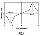
- the signal light pulse is a Gaussian pulse with average power E and with linear chirp
- the chirp parameter is C
- the bandwidth of the signal light is ⁇
- the product of the second order derivative of the propagation constant ⁇ and the length of the dispersion medium is B 2
- the output voltage V(C, ⁇ , B 2 ) is given by the following expression.
- the pulse width narrows on the first path and hence its peak power increases.
- the output voltage of the nonlinear photo-detector 13-1 of the first path increases, whereas that of the nonlinear photo-detector 13-2 of the second path decreases.
- a difference detector 14 detects the difference (voltage difference) between the electric signals output from the nonlinear photo-detectors 13-1 and 13-2 of the two paths.
- nonlinear photo-detectors 13-1 and 13-2 a nonlinear photo-detecting device with two-photon absorption can be used.
- a filter that passes only the second harmonic light can be interposed between the nonlinear medium and photo-detector.
- the dispersion media 12-1 and 12-2 do not cause any difference between the output peak powers so that the differential signal is nearly zero. In other words, as long as the signal light is affected by the dispersion, the differential signal is generated and the chirp detection is carried out.
- a coupler for dividing part of the signal light to be supplied to the nonlinear photo-detector a linear photo-detector for producing an electric signal V 1 with the intensity proportional to the optical intensity
- a normalization section for normalizing the electric signal V 2 output from the nonlinear photo-detector to an electric signal V 2 /V 1 n by the electric signal V 1 .
- Fig. 5 is a block diagram showing a first configuration of the chirp measurement apparatus in accordance with the present invention.
- the input signal light traveling through the optical fiber transmission line 10 undergoes 1/10 power division by a 90:10 optical coupler 21, followed by further splitting the signal light to two paths by a 50:50 optical coupler 22 that divides it to two portions with equal power.
- a first path (path 1) of the two paths is provided with a single mode fiber (SMF) 23 with the total dispersion amount +D ( ⁇ 0) at the used wavelength as a dispersion medium
- the second path (path 2) is provided a dispersion compensating fiber (DCF) 24 with the total dispersion amount -D ( ⁇ 0) at the used wavelength as a dispersion medium.
- SMF single mode fiber
- DCF dispersion compensating fiber
- the two paths are provided with Si-APDs (Silicon Avalanche Photo Diodes) 25-1 and 25-2 that exhibit two-photon absorption in a 1.5 ⁇ m band as nonlinear photo-detectors for receiving the signal light beams passing through the individual dispersion media 23 and 24, and for outputting electric signals with the intensities proportional to the square of the intensity of the input light beams. Their response frequency is much lower than the transmission rate so that they can produce a DC voltage as their output.
- a differential amplifier 26 detects the difference between the output voltages of the Si-APDs 25-1 and 25-2 of the two paths, and outputs the differential signal (voltage difference).
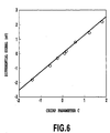
- Fig. 6 is a graph illustrating the output voltage of the differential amplifier 26 versus a measured chirp parameter.
- the Si-APDs have the response frequency of 10 MHz against the transmission rate of 10 Gbit/s.
- the single mode fiber has the dispersion value of +16 ps/nm at the wavelength 1552 nm, and the dispersion compensating fiber has the dispersion value of -16 ps/nm at the same wavelength.
- the signal light is an optical pulse with a bandwidth of 545 GHz fed from a 10 GHz mode-locked fiber laser.
- the output voltage exhibits a linear characteristic for the chirp parameter, which is consistent with the theoretical calculation result of the differential signal as illustrated in Fig. 4.
- the output voltage of the differential amplifier 26 takes the values corresponding to the magnitude of the dispersion (chirp), it can be used as the chirp detection signal of the optical pulse traveling through the optical fiber transmission line 10.
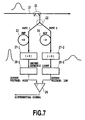
- Fig. 7 is a block diagram showing a second configuration of the chirp measurement apparatus in accordance with the present invention.
- the second configuration is characterized in that it employs KH 2 PO 4 (KDPs) 27-1 and 27-2, an SHG (second harmonic generation) crystal, as the nonlinear media for generating the second harmonic light of the input light in place of the Si-APDs used as the nonlinear photo-detectors in the first configuration, and employs photomultipliers 28-1 and 28-2 as the photo-detectors for converting the second harmonic light to electric signals.
- KDPs KH 2 PO 4
- SHG second harmonic generation
- the light beams output from the single mode fiber (SMF) 23 and dispersion compensating fiber (DCF) 24 are incident onto the KDPs 27-1 and 27-2 via focusing lenses not shown.
- the KDPs 27-1 and 27-2 generate the second harmonic light beams with the output intensity proportional to the square of the input optical intensity.
- the second harmonic light beams (700 nm wavelength band) are incident onto the photomultipliers 28-1 and 28-2 with a sensitive wavelength range of 300-820 nm.
- first and second configurations to utilize a tunable dispersion equalizer such as a fiber Bragg grating or VIPA in place of the single mode fiber (SMF) 23 and dispersion compensating fiber (DCF) 24 used as the dispersion media disposed in the two paths.
- a tunable dispersion equalizer such as a fiber Bragg grating or VIPA in place of the single mode fiber (SMF) 23 and dispersion compensating fiber (DCF) 24 used as the dispersion media disposed in the two paths.
- SMF single mode fiber
- DCF dispersion compensating fiber
- Fig. 8 is a block diagram showing a fifth configuration of the chirp measurement apparatus in accordance with the present invention. It is assumed in the foregoing configurations that the signal light is split to the two equal paths in terms of power by the 50:50 optical coupler 22. In contrast, the present configuration is an example that can cope with a case where the input signal light is split into two unequal paths in terms of power, or into two paths having different losses.
- the configuration has optical amplifiers 29-1 and 29-2 disposed before the single mode fiber (SMF) 23 and dispersion compensating fiber (DCF) 24 in the two paths.
- SMF single mode fiber
- DCF dispersion compensating fiber
- the optical amplifiers 29-1 and 29-2 regulate the optical signal intensities so that the intensities of the electric signals supplied from the two paths to the differential amplifier 26 become equal. This makes it possible to adjust the intensities even if the input light is not divided into two equal portions to the two paths, or the two paths have different losses.
- the optical amplifiers 29-1 and 29-2 When using an erbium doped fiber amplifier (EDFA) for the optical amplifiers 29-1 and 29-2, for example, their optical signal intensities are controllable by the bias voltages.
- the optical amplifiers 29-1 and 29-2 can carry out the APC (Automatic Power Control) such that the average input power to the nonlinear photo-detectors 13-1 and 13-2 become constant.
- APC Automatic Power Control
- the optical amplifiers 29-1 and 29-2 of the two paths are unnecessary.
- an optical amplifier (EDFA) can be placed before the 50:50 optical coupler 22 in order to make the average input power to the nonlinear photo-detectors 13-1 and 13-2 constant.
- At least one of the optical amplifiers 29-1 and 29-2 may include an additional variable optical attenuator, or to be replaced by a variable optical attenuator to control the optical power of the two paths.
- the configuration is designed such that the splitting ratio to and the losses of the two optical paths are compensated for in advance before detecting the magnitude of the dispersion of the optical fiber transmission line 10.
- the optical amplifiers 29-1 and 29-2 control the intensities of the optical signals such that the intensities of the electric signals supplied from the two paths to the differential amplifier 26 become equal when the input signal light unaffected by the dispersion is input (broken line waveforms in Fig. 8).
- Fig. 9 is a block diagram showing a sixth configuration of the chirp measurement apparatus in accordance with the present invention.
- the configuration is characterized in that in the fifth configuration, a control circuit 30 feeds the differential signal output from the differential amplifier 26 back to at least one of the optical amplifiers 29-1 and 29-2 of the two paths in order to regulate the differential signal to a minimum (zero) when the input signal light (broken line waveforms in Fig. 9) unaffected by the dispersion of the optical fiber transmission line is input.
- At least one of the optical amplifiers 29-1 and 29-2 may include an additional variable optical attenuator, or to be replaced by a variable optical attenuator to control the optical power of the two paths.
- the configuration is designed such that the splitting ratio to and the losses of the two optical paths are compensated for in advance before detecting the magnitude of the dispersion of the optical fiber transmission line 10.
- the optical amplifiers 29-1 and 29-2 control the intensities of the optical signals such that the intensities of the electric signals supplied from the two paths to the differential amplifier 26 become equal when the input signal light unaffected by the dispersion is input (broken line waveforms in Fig. 9).
- electric signal adjusting sections for example, electric amplifiers
- the control circuit 30 it is also possible to use, instead of the optical amplifiers 29-1 and 29-2, electric signal adjusting sections (for example, electric amplifiers) installed at the output side of the nonlinear photo-detectors 13-1 and 13-2 in order to equalize the intensities of the electric signals supplied from the two paths to the differential amplifier 26 by carrying out feedback control of at least one of them by the control circuit 30.
- Fig. 10 is a block diagram showing a seventh configuration of the chirp measurement apparatus in accordance with the present invention.
- the configuration is characterized in that in the first to sixth configurations, an optical coupler 32 is interposed between the 90:10 optical coupler 21 and the 50:50 optical coupler 22 to divide part of the signal light, and a photodiode 33, which is a linear photo-detecting device, is provided to detect it.
- the output electric signal is V 1 .
- normalization circuits 34-1 and 34-2 for normalizing the output electric signals V 21 and V 22 of the nonlinear photo-detectors 13-1 and 13-2 are provided between the nonlinear photo-detectors 13-1 and 13-2 and the differential amplifier 26.
- the nonlinear photo-detectors 13-1 and 13-2 output the electric signals V 21 and V 22 with the intensities proportional to the nth power of the signal light beams
- the normalization circuits 34-1 and 34-2 output the normalized electric signals V 21 /V 1 n and V 22 /V 1 n .
- the differential amplifier 26 outputs the differential signal in which fluctuations of the input optical power are compensated for.
- normalization means normalizing the electric signals V 21 and V 22 output from the nonlinear photo-detectors 13-1 and 13-2 by the output signal V 1 (or the nth power thereof) of the photodiode 33.
- Fig. 11 is a block diagram showing an eighth configuration of the chirp measurement apparatus in accordance with the present invention.
- the configuration is characterized in that in the first to sixth configurations, optical couplers 32-1 and 32-2 are provided before the nonlinear photo-detectors 13-1 and 13-2 of the two paths to divide parts of the signal light beams, and photodiodes 33-1 and 33-2, which are a linear photo-detecting device, are provided to receive them.
- the output electric signals of the photodiodes 33-1 and 33-2 are V 11 and V 12 .
- normalization circuits 34-1 and 34-2 for normalizing the output electric signals V 21 and V 22 of the nonlinear photo-detectors 13-1 and 13-2 are provided between the nonlinear photo-detectors 13-1 and 13-2 and the differential amplifier 26.
- the nonlinear photo-detectors 13-1 and 13-2 output the electric signals V 21 and V 22 with the intensities proportional to the nth power of the signal light beams
- the normalization circuits 34-1 and 34-2 output the normalized electric signals V 21 /V 11 n and V 22 /V 12 n .
- the differential amplifier 26 outputs the differential signal in which fluctuations of the input optical power are compensated for.
- normalization means normalizing the electric signals V 21 and V 22 output from the nonlinear photo-detectors 13-1 and 13-2 by the output signals V 11 and V 12 (or the nth power thereof) of the photodiodes 33-1 and 33-2.
- Fig. 12 is a block diagram showing a ninth configuration of the chirp measurement apparatus in accordance with the present invention.
- the input signal light traveling through the optical fiber transmission line 10 undergoes 1/10 power division by the 90:10 optical coupler 21.
- the bypath includes an optical fiber 35 with the total dispersion amount of D ( ⁇ 0) at the used wavelength.
- a nonlinear photo-detector 13 is provided which outputs an electric signal with the intensity proportional to the nth power of the input optical intensity of the signal passing through the light optical fiber 35.
- the output voltage of the nonlinear photo-detector 13 takes different values depending on the magnitude of the dispersion (chirp), it can be used as the dispersion detection signal of the optical fiber transmission line 10. More specifically, it is possible to measure the chirp by storing in a processing unit (not shown) a cross-reference table that gives chirp values for the output voltage of the nonlinear photo-detector 13, which are measured in advance, and by referring to the cross-reference table by the output voltage varying depending on the magnitude of the chirp.
- Fig. 13 is a block diagram showing a tenth configuration of the chirp measurement apparatus in accordance with the present invention.
- the configuration is characterized in that in the ninth configuration, an optical coupler 32 is provided before the nonlinear photo-detector 13 to divide part of the input light, and a photodiode 33 which is a linear photo-detecting device detects it. Assume that the electric signal output from the photodiode 33 is V 1 .
- a normalization circuit 34 is provided at the output of the nonlinear photo-detector 13 to normalize its output electric signal V 2 .
- the normalization circuit 34 outputs the normalized electric signal V 2 /V 1 n , in which the fluctuations of the input optical power is compensated for.
- the output electric signal of the normalization circuit 34 takes different values depending on the magnitude of the dispersion (chirp)
- it is possible to measure the chirp by storing in the processing unit (not shown) the cross-reference table that gives chirp values for the output electric signal of the normalization circuit 34, which are measured in advance, and by referring to the cross-reference table by the output voltage varying depending on the magnitude of the chirp.
- Fig. 14 is a block diagram showing an 11th configuration of the chirp measurement apparatus in accordance with the present invention.
- the configuration is characterized in that polarization beam splitters 15-1 and 15-2 are provided after the dispersion media 12-1 and 12-2 to split the optical signals fed from the dispersion media 12-1 and 12-2 to polarized waves orthogonal to each other.
- the split polarized waves are supplied to the nonlinear photo-detectors 13-1a and 13-1b and 13-2a and 13-2b that are installed for the individual polarized waves so that they output the electric signals (voltages) with the intensities proportional to the nth power of the optical intensities of the individual signal light beams, where n > 1.
- the electric signals are supplied to a processing unit 16.
- the electric signals supplied to the processing unit 16 take different values depending on the magnitude of the dispersion (chirp) of the individual polarized waves, it is possible to measure the chirp and output the measurement result as the chirp signal 17 by storing in the processing unit 16 the cross-reference table that gives chirp values for the output electric signals, which are measured in advance, and by referring to the cross-reference table by the output voltage varying depending on the magnitude of the chirp.
- the dispersion compensating apparatus described in the present embodiment is characterized in that it uses the chirp measurement apparatus in accordance with the present invention, measures the chirp of the optical signal output from the optical fiber transmission line, and controls the tunable dispersion equalizer such that the chirp is canceled out.
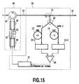
- Fig. 15 is a block diagram showing a configuration of the dispersion compensating apparatus in accordance with the present invention.
- the dispersion compensating apparatus comprises a tunable dispersion equalizer 40 and the chirp measurement apparatus 20 in accordance with the present invention.
- the chirp measurement apparatus 20 feeds the differential signal output from the differential amplifier 26 back to the tunable dispersion equalizer 40 via a control circuit 31.
- chirp measurement apparatus 20 of Fig. 15 is that of the first configuration, it is obvious that other chirp measurement apparatuses described in the other embodiments are also applicable.
- the chirp measurement apparatus 20 is placed after the tunable dispersion equalizer 40 as shown in Fig. 15 (see also Fig. 16A), the chirp measurement apparatus 20 can be placed before the tunable dispersion equalizer 40 as in the configuration of Fig. 16B, offering the same advantages.
- the configuration as shown in Fig. 15 employs a nonlinear chirped fiber Bragg gratings paired type tunable dispersion equalizer as the tunable dispersion equalizer 40.
- the second port of the four-port optical circulator 41 is connected to the longer wavelength side of a chirp fiber grating 42.
- the third port of the four-port optical circulator 41 is connected to the shorter wavelength side of a chirp fiber grating 43.
- the first port of the four-port optical circulator 41 is used as the input port connected to the optical fiber transmission line 10, and the fourth port is used as the output port.
- the tuning section of the tunable dispersion equalizer 40 has a structure in which the two chirped fiber Bragg gratings 42 and 43 are fixed to piezoelectric transducers 44 adhesively. Applying a voltage to the piezoelectric transducers to control expansion and contraction from the both sides enables the reflected wavelength bands of the individual chirped fiber Bragg gratings 42 and 43 to be shifted in the same direction, thereby being able to alter the wavelength dispersion characteristics for the transmitting light.
- the dispersion value variable range of the tunable dispersion equalizer 40 is -16 ps/nm ⁇ +16 ps/nm at the wavelength of the signal light, for example.
- the dispersion value of the single mode fiber (SMF) 23 of the chirp measurement apparatus 20 is +16 ps/nm at the wavelength of the signal light
- the dispersion compensating fiber (DCF) 24 is -16 ps/nm at the wavelength of the signal light.
- the paths 1 and 2 undergo the following influence before the adaptive equalization as illustrated in Fig. 2A.
- the pulse width narrows and the peak power increases because of the small effect of the dispersion.
- the pulse width broadens and the peak power reduces because of the large effect of the dispersion. Accordingly, the output voltage of the Si-APD 25-1 of the path 1 is high, and the output voltage of the Si-APD 25-2 of the path 2 is low.
- the differential amplifier 26 outputs the differential signal corresponding to the difference between the output voltages.
- the differential signal is supplied to control circuit 31 comprising a proportional circuit and an integral circuit.
- the control circuit 31 converts the differential signal to a driving signal for controlling the piezoelectric transducers 44 of the tunable dispersion equalizer 40.
- the control circuit 31 controls the expansion and contraction of the chirp fiber gratings 42 and 43 such that the differential signal becomes zero.
- the zero dispersion wavelength of the tunable dispersion equalizer 40 shifts following the dispersion fluctuations in the optical fiber transmission line 10 as illustrated in Fig. 17, thereby enabling the adaptive dispersion equalization (Fig. 2B).
- the chirp measurement apparatus 20 in accordance with the present invention utilizes the two-photon absorption effect rather than the clock extraction method to obtain the differential signal. As a result, it is applicable to 10 Gbit/s ⁇ 40 Gbit/s optical transmission systems, for example, and even to 160 Gbit/s optical transmission system independently of the bit rate of the transmission system.
- Fig.18 is a blockdiagram showing a twelfth configration of the chirp measurement apparatus in accordance with the present invention.
- the twelfth configration is characterized in that in the eleventh configration, optical couplers 32-1 and 32-2 are provided before the polarization beam splitters 15-1 and 15-2 followed by the nonlinear photo-detectors 13-1a and 13-1b and 13-2a and 13-2b of the two paths to divide parts of the signal light beams, and photodiodes 33-1 and 33-2 which are linear photo-detecting devices provided to receive them.
- the electric signals output from the linear photo-detecting devices are supplied to a processing unit 16.
- the electric signals supplied to the processing unit 16 are normalized and take different values depending on the magnitude of the dispersion (chirp) of the individual polarized waves, it is possible to measure the chirp and output the measurement result as the chirp signal 17 by storing in the processing unit 16 the cross-reference table that gives chirp values for the output electric signals, which are measured in advance, and by referring to the cross-reference table by the output voltage varying depending on the magnitude of the chirp.
Landscapes
- Physics & Mathematics (AREA)
- Electromagnetism (AREA)
- Engineering & Computer Science (AREA)
- Computer Networks & Wireless Communication (AREA)
- Signal Processing (AREA)
- Optical Communication System (AREA)
- Optical Modulation, Optical Deflection, Nonlinear Optics, Optical Demodulation, Optical Logic Elements (AREA)
- Investigating Or Analysing Materials By Optical Means (AREA)
Applications Claiming Priority (4)
| Application Number | Priority Date | Filing Date | Title |
|---|---|---|---|
| JP2001337865 | 2001-11-02 | ||
| JP2001337865 | 2001-11-02 | ||
| JP2002164437 | 2002-06-05 | ||
| JP2002164437A JP2003204303A (ja) | 2001-11-02 | 2002-06-05 | 分散検知装置および分散検知方法 |
Publications (3)
| Publication Number | Publication Date |
|---|---|
| EP1309115A2 true EP1309115A2 (fr) | 2003-05-07 |
| EP1309115A3 EP1309115A3 (fr) | 2004-01-14 |
| EP1309115B1 EP1309115B1 (fr) | 2006-08-30 |
Family
ID=26624317
Family Applications (1)
| Application Number | Title | Priority Date | Filing Date |
|---|---|---|---|
| EP02024294A Expired - Lifetime EP1309115B1 (fr) | 2001-11-02 | 2002-10-31 | Procédé de mesure du chirp |
Country Status (4)
| Country | Link |
|---|---|
| US (4) | US6958467B2 (fr) |
| EP (1) | EP1309115B1 (fr) |
| JP (1) | JP2003204303A (fr) |
| DE (1) | DE60214316T8 (fr) |
Cited By (2)
| Publication number | Priority date | Publication date | Assignee | Title |
|---|---|---|---|---|
| EP1693976A1 (fr) * | 2005-02-18 | 2006-08-23 | Fujitsu Limited | Surveillance de la variation de dispersion de longueurs d'onde par absorption photonique |
| US7668459B2 (en) | 2002-07-23 | 2010-02-23 | Nippon Telegraph And Telephone Corporation | Dispersion monitoring method and apparatus and dispersion slope temperature dependency compensation method and apparatus |
Families Citing this family (12)
| Publication number | Priority date | Publication date | Assignee | Title |
|---|---|---|---|---|
| JP4082992B2 (ja) * | 2002-11-21 | 2008-04-30 | 富士通株式会社 | 光分散モニタ装置および方法、並びに、それを用いた光伝送システム |
| IL154647A (en) * | 2003-02-27 | 2008-04-13 | Eci Telecom Ltd | Traffic management in optical communication networks |
| WO2008066599A1 (fr) * | 2006-09-22 | 2008-06-05 | Pyrotek, Inc. | Couplage à réduction de chaleur |
| IL190890A0 (en) * | 2008-04-15 | 2008-12-29 | Eci Telecom Ltd | Technique for detection of optical data signals |
| JP2010093243A (ja) * | 2008-09-09 | 2010-04-22 | Hikari Physics Kenkyusho:Kk | 光ピークパワー検出装置及び該装置を利用したパルスレーザー発生装置 |
| CN104467969B (zh) * | 2014-12-10 | 2017-03-22 | 北京理工大学 | 分数阶傅里叶变换测量光纤链路色散的方法 |
| CN104967480B (zh) * | 2015-07-15 | 2016-12-07 | 北京理工大学 | 采用分数阶傅里叶变换监测光纤链路非线性效应的方法 |
| JP6597445B2 (ja) * | 2016-03-25 | 2019-10-30 | 富士通株式会社 | 透過特性をモニタする装置および方法 |
| CN110601752B (zh) * | 2019-08-16 | 2021-04-09 | 武汉光迅科技股份有限公司 | 一种啁啾测量装置及方法、计算机可读存储介质 |
| WO2022000338A1 (fr) * | 2020-06-30 | 2022-01-06 | 华为技术有限公司 | Circuit de traitement, module optique et procédé de détection de chirp |
| JPWO2024189821A1 (fr) * | 2023-03-15 | 2024-09-19 | ||
| US20250012664A1 (en) * | 2023-07-05 | 2025-01-09 | Google Llc | Apparatus And Method For Measuring Chirp In Fiber Optical Transmitters |
Family Cites Families (6)
| Publication number | Priority date | Publication date | Assignee | Title |
|---|---|---|---|---|
| JPH04274724A (ja) | 1991-03-02 | 1992-09-30 | Fujikura Ltd | Otdr装置 |
| JP3771755B2 (ja) | 1999-08-11 | 2006-04-26 | 日本電信電話株式会社 | 光自動等化器 |
| EP1279245A2 (fr) * | 2000-02-18 | 2003-01-29 | Corning Incorporated | Detecteur electrique pour commande adaptative de dispersion chromatique dans des systemes optiques |
| US6586724B2 (en) * | 2001-04-26 | 2003-07-01 | Nortel Networks Limited | Chromatic dispersion discriminator |
| US6657186B2 (en) * | 2001-04-26 | 2003-12-02 | Nortel Networks Limited | Chromatic dispersion discriminator |
| US7460785B2 (en) * | 2001-05-23 | 2008-12-02 | Lucent Technologies Inc. | Performance monitoring in an optical communication system |
-
2002
- 2002-06-05 JP JP2002164437A patent/JP2003204303A/ja active Pending
- 2002-10-31 US US10/284,286 patent/US6958467B2/en not_active Expired - Fee Related
- 2002-10-31 DE DE60214316T patent/DE60214316T8/de active Active
- 2002-10-31 EP EP02024294A patent/EP1309115B1/fr not_active Expired - Lifetime
-
2005
- 2005-09-23 US US11/232,963 patent/US20060022123A1/en not_active Abandoned
-
2008
- 2008-05-02 US US12/114,707 patent/US20080212962A1/en not_active Abandoned
- 2008-05-02 US US12/114,688 patent/US20080296481A1/en not_active Abandoned
Cited By (2)
| Publication number | Priority date | Publication date | Assignee | Title |
|---|---|---|---|---|
| US7668459B2 (en) | 2002-07-23 | 2010-02-23 | Nippon Telegraph And Telephone Corporation | Dispersion monitoring method and apparatus and dispersion slope temperature dependency compensation method and apparatus |
| EP1693976A1 (fr) * | 2005-02-18 | 2006-08-23 | Fujitsu Limited | Surveillance de la variation de dispersion de longueurs d'onde par absorption photonique |
Also Published As
| Publication number | Publication date |
|---|---|
| EP1309115B1 (fr) | 2006-08-30 |
| DE60214316T2 (de) | 2007-04-05 |
| JP2003204303A (ja) | 2003-07-18 |
| US20080212962A1 (en) | 2008-09-04 |
| US20080296481A1 (en) | 2008-12-04 |
| DE60214316T8 (de) | 2007-08-16 |
| US6958467B2 (en) | 2005-10-25 |
| US20060022123A1 (en) | 2006-02-02 |
| DE60214316D1 (de) | 2006-10-12 |
| US20030086713A1 (en) | 2003-05-08 |
| EP1309115A3 (fr) | 2004-01-14 |
Similar Documents
| Publication | Publication Date | Title |
|---|---|---|
| US20080212962A1 (en) | Chirp measurement method, chirp measurement apparatus and their application | |
| US6671464B1 (en) | Polarization mode dispersion compensator and compensation method | |
| US6661974B1 (en) | Optical transmitter and optical transmission system | |
| US7489880B2 (en) | Apparatus and method for measuring the dispersion of a fiber span | |
| US6104515A (en) | Method and apparatus for providing high-order polarization mode dispersion compensation using temporal imaging | |
| US7058311B1 (en) | System and method for dispersion compensation in an optical communication system | |
| US5915052A (en) | Loop status monitor for determining the amplitude of the signal components of a multi-wavelength optical beam | |
| US20040090659A1 (en) | Method of tuning wavelength tunable electro-absorption modulators | |
| US7646983B2 (en) | Apparatus and method for commissioning an optical transmission system | |
| EP1385281B1 (fr) | Méthode et dispositif de surveillance de dispersion, et méthode et dispositif pour compenser la dépendance en température de la pente de dispersion | |
| EP3185443A1 (fr) | Système de télécommunications à multiplexage par répartition en longueur d'onde à compensation automatique de dispersion chromatique | |
| US20090310977A1 (en) | Systems for deploying an optical network | |
| US20050226628A1 (en) | Method and device for wavelength dispersion compensation | |
| US20060140636A1 (en) | Optical communication system | |
| JP3147563B2 (ja) | 光分散補償方法および光分散補償器 | |
| US6583905B1 (en) | Apparatus and method for reducing SPM/GVD in optical systems | |
| EP0598387B1 (fr) | Ligne de transmission optique et technique de réduction de distorsion | |
| EP0963066A1 (fr) | Dispositif et méthode pour réduire l'interaction entre la modulation de la phase propre et la dispersion due à la vitesse de groupe dans des systèmes optiques | |
| JP2003198467A (ja) | 波形歪み検出装置、システム、及び方法 | |
| Drummond et al. | Tunable optical dispersion compensator based on power splitting between two dispersive media | |
| US20060222373A1 (en) | Methods for upgrading and deploying an optical network | |
| Schiffini et al. | Field Demonstration of All optical in-line Wavelength Conversion in a WDM 40 Gbit/s Dispersion Managed link using a Polarization insensitive Ti: PPLN Converter | |
| Qureshi et al. | Tunable polarization maintaining fiber Bragg grating based OSNR monitor | |
| JP2005341439A (ja) | 分散検知装置 | |
| JP2005338009A (ja) | 分散検知装置 |
Legal Events
| Date | Code | Title | Description |
|---|---|---|---|
| PUAI | Public reference made under article 153(3) epc to a published international application that has entered the european phase |
Free format text: ORIGINAL CODE: 0009012 |
|
| 17P | Request for examination filed |
Effective date: 20021128 |
|
| AK | Designated contracting states |
Designated state(s): AT BE BG CH CY CZ DE DK EE ES FI FR GB GR IE IT LI LU MC NL PT SE SK TR |
|
| AX | Request for extension of the european patent |
Extension state: AL LT LV MK RO SI |
|
| PUAL | Search report despatched |
Free format text: ORIGINAL CODE: 0009013 |
|
| AK | Designated contracting states |
Kind code of ref document: A3 Designated state(s): AT BE BG CH CY CZ DE DK EE ES FI FR GB GR IE IT LI LU MC NL PT SE SK TR |
|
| AX | Request for extension of the european patent |
Extension state: AL LT LV MK RO SI |
|
| 17Q | First examination report despatched |
Effective date: 20040823 |
|
| AKX | Designation fees paid |
Designated state(s): DE FR GB |
|
| GRAP | Despatch of communication of intention to grant a patent |
Free format text: ORIGINAL CODE: EPIDOSNIGR1 |
|
| GRAS | Grant fee paid |
Free format text: ORIGINAL CODE: EPIDOSNIGR3 |
|
| GRAA | (expected) grant |
Free format text: ORIGINAL CODE: 0009210 |
|
| AK | Designated contracting states |
Kind code of ref document: B1 Designated state(s): DE FR GB |
|
| REG | Reference to a national code |
Ref country code: GB Ref legal event code: FG4D |
|
| REF | Corresponds to: |
Ref document number: 60214316 Country of ref document: DE Date of ref document: 20061012 Kind code of ref document: P |
|
| ET | Fr: translation filed | ||
| PLBE | No opposition filed within time limit |
Free format text: ORIGINAL CODE: 0009261 |
|
| STAA | Information on the status of an ep patent application or granted ep patent |
Free format text: STATUS: NO OPPOSITION FILED WITHIN TIME LIMIT |
|
| 26N | No opposition filed |
Effective date: 20070531 |
|
| PGFP | Annual fee paid to national office [announced via postgrant information from national office to epo] |
Ref country code: FR Payment date: 20121113 Year of fee payment: 11 Ref country code: DE Payment date: 20121022 Year of fee payment: 11 |
|
| PGFP | Annual fee paid to national office [announced via postgrant information from national office to epo] |
Ref country code: GB Payment date: 20121023 Year of fee payment: 11 |
|
| REG | Reference to a national code |
Ref country code: DE Ref legal event code: R119 Ref document number: 60214316 Country of ref document: DE |
|
| GBPC | Gb: european patent ceased through non-payment of renewal fee |
Effective date: 20131031 |
|
| REG | Reference to a national code |
Ref country code: DE Ref legal event code: R079 Ref document number: 60214316 Country of ref document: DE Free format text: PREVIOUS MAIN CLASS: H04B0010180000 Ipc: H04B0010250700 |
|
| PG25 | Lapsed in a contracting state [announced via postgrant information from national office to epo] |
Ref country code: GB Free format text: LAPSE BECAUSE OF NON-PAYMENT OF DUE FEES Effective date: 20131031 |
|
| REG | Reference to a national code |
Ref country code: FR Ref legal event code: ST Effective date: 20140630 |
|
| REG | Reference to a national code |
Ref country code: DE Ref legal event code: R119 Ref document number: 60214316 Country of ref document: DE Effective date: 20140501 Ref country code: DE Ref legal event code: R079 Ref document number: 60214316 Country of ref document: DE Free format text: PREVIOUS MAIN CLASS: H04B0010180000 Ipc: H04B0010250700 Effective date: 20140709 |
|
| PG25 | Lapsed in a contracting state [announced via postgrant information from national office to epo] |
Ref country code: FR Free format text: LAPSE BECAUSE OF NON-PAYMENT OF DUE FEES Effective date: 20131031 Ref country code: DE Free format text: LAPSE BECAUSE OF NON-PAYMENT OF DUE FEES Effective date: 20140501 |