EP1309119A2 - Unité de branchement - Google Patents
Unité de branchement Download PDFInfo
- Publication number
- EP1309119A2 EP1309119A2 EP02292597A EP02292597A EP1309119A2 EP 1309119 A2 EP1309119 A2 EP 1309119A2 EP 02292597 A EP02292597 A EP 02292597A EP 02292597 A EP02292597 A EP 02292597A EP 1309119 A2 EP1309119 A2 EP 1309119A2
- Authority
- EP
- European Patent Office
- Prior art keywords
- optical
- input
- interleaver
- branching unit
- optical signals
- Prior art date
- Legal status (The legal status is an assumption and is not a legal conclusion. Google has not performed a legal analysis and makes no representation as to the accuracy of the status listed.)
- Withdrawn
Links
- 230000003287 optical effect Effects 0.000 claims abstract description 413
- 238000000034 method Methods 0.000 claims description 3
- 230000005540 biological transmission Effects 0.000 abstract description 25
- 238000003780 insertion Methods 0.000 description 3
- 230000037431 insertion Effects 0.000 description 3
- 239000002131 composite material Substances 0.000 description 2
- 239000000835 fiber Substances 0.000 description 2
- 238000004519 manufacturing process Methods 0.000 description 2
- 238000002310 reflectometry Methods 0.000 description 2
- 230000002441 reversible effect Effects 0.000 description 2
- 238000013459 approach Methods 0.000 description 1
- 230000007812 deficiency Effects 0.000 description 1
- 238000013461 design Methods 0.000 description 1
- 239000006185 dispersion Substances 0.000 description 1
Images

Classifications
-
- H—ELECTRICITY
- H04—ELECTRIC COMMUNICATION TECHNIQUE
- H04J—MULTIPLEX COMMUNICATION
- H04J14/00—Optical multiplex systems
- H04J14/02—Wavelength-division multiplex systems
- H04J14/0201—Add-and-drop multiplexing
- H04J14/0202—Arrangements therefor
- H04J14/0209—Multi-stage arrangements, e.g. by cascading multiplexers or demultiplexers
-
- H—ELECTRICITY
- H04—ELECTRIC COMMUNICATION TECHNIQUE
- H04J—MULTIPLEX COMMUNICATION
- H04J14/00—Optical multiplex systems
- H04J14/02—Wavelength-division multiplex systems
- H04J14/0201—Add-and-drop multiplexing
- H04J14/0202—Arrangements therefor
- H04J14/0208—Interleaved arrangements
-
- H—ELECTRICITY
- H04—ELECTRIC COMMUNICATION TECHNIQUE
- H04J—MULTIPLEX COMMUNICATION
- H04J14/00—Optical multiplex systems
- H04J14/02—Wavelength-division multiplex systems
- H04J14/0201—Add-and-drop multiplexing
- H04J14/0202—Arrangements therefor
- H04J14/0213—Groups of channels or wave bands arrangements
-
- H—ELECTRICITY
- H04—ELECTRIC COMMUNICATION TECHNIQUE
- H04J—MULTIPLEX COMMUNICATION
- H04J14/00—Optical multiplex systems
- H04J14/02—Wavelength-division multiplex systems
- H04J14/0201—Add-and-drop multiplexing
- H04J14/0215—Architecture aspects
- H04J14/0217—Multi-degree architectures, e.g. having a connection degree greater than two
-
- H—ELECTRICITY
- H04—ELECTRIC COMMUNICATION TECHNIQUE
- H04J—MULTIPLEX COMMUNICATION
- H04J14/00—Optical multiplex systems
- H04J14/02—Wavelength-division multiplex systems
- H04J14/0201—Add-and-drop multiplexing
- H04J14/0215—Architecture aspects
- H04J14/0219—Modular or upgradable architectures
Definitions
- the present invention relates to an optical branching unit for optical transmission systems.
- Modern optical communications systems typically use many separate but interconnected optical transmission lines. These optical transmission lines are typically interconnected using branching units which allow selected optical signals to be removed from any one optical transmission line and inserted in to another connected optical transmission line.
- WDM wavelength division multiplex
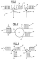
- FIG. 1 illustrates an example of such an arrangement.
- the branching unit generally denoted 1 comprises a first circulator 2 a second circulator 3 and an intermediate reflective grating 4 placed in between the two circulators.
- the first circulator 2 has one optical input 5 and two optical outputs 6 and 7, while the second circulator 3 has two optical inputs 8 and 9, and one optical output 10.
- One optical output 7 of the first circulator 2 is in optical connection with one optical input 8 of the second circulator 3.
- a WDM optical signal 11 is input to optical input 5 of the branching unit, the entire signal is output at optical output 7 of the first circulator 2.
- -Selected wavelength channels such as channel 12, are subsequently reflected by the reflective grating 4 and redirected in to the circulator 2 for output at optical output 6.
- one selected wavelength channel may be dropped from the input signal 11 by appropriately choosing the wavelength reflectivity of the reflective grating 4.
- the remaining components 13 of the optical signal 11 then pass to an optical input 8 of the second circulator 3, and are combined with an optical channel 12 which is input at the other optical input 9 of the second circulator 3.
- the channel 12 is reflected by the reflective grating 4, in a manner similar to the reflection of the corresponding channel 12 output from the optical output 7 of the first circulator 2.
- the combined optical signal 15 is then output at the optical output 10 of the second circulator 3.
- a single optical channel 12 may be dropped from, and added to, optical signal 11.
- Additional optical channels may be dropped from optical input signal 11 by employing additional reflective grating elements placed in line with grating element 4 which each have a pre-selected reflectivity appropriate to the channel to be reflected thereby.
- additional reflective grating elements placed in line with grating element 4 which each have a pre-selected reflectivity appropriate to the channel to be reflected thereby.
- Each such traversal incurs loss in the respective channel, and therefore the greater number of traversals required, the greater the loss incurred.
- a larger number of wavelength channels are required to be dropped, a correspondingly large number of gratings will be required. In such circumstances the losses may be high and often produce a large "loss tilt" whereby the channel reflected in the last grating suffers a much higher loss than the channel reflected in the first grating.
- Channels reflected by intermediate gratings suffer a loss intermediate these two extremes and the result is a strong drop-off, or "tilt", in the intensities of successive channels.
- the wavelength channel 12 that is dropped from the incoming signal 11 is the same wavelength channel that is subsequently added by the second circulator of the branching unit to provide output signal 15. This is necessary in order to avoid optical hole burning in the optical signal output by the branching unit as would occur where the hole 16 in the intermediate signal 13 of the branching unit not filled by the optical channel 12 added thereto by the second circulator 3 of the branching unit.
- this seriously reduces the network routing capacity of any network employing branching units of this type since any channels removed from an optical transmission line by the branching unit must be subsequently added to the transmission line by the same branching unit.
- wavelength dependant add and drop branching units based on reflective gratings are generally difficult to manufacture, and are limited in the number of channels they may add and drop. Indeed, due to problems associated with chromatic dispersion in the reflective grating implied in such branching units, data transmission rates are limited to 2.5 gigabits per second through such branching units.
- the present invention aims to provide a branching unit which overcomes at least some of these deficiencies in the prior art.
- the present invention proposes to employ a plurality of interconnected optical interleavers in a branching unit for the purposes of separating at least some optical signals input thereto into separate component signals for output on separate branches, and for combining separated component optical signals with other input optical signals for output on common branches of the branching unit.
- An interleaver is an optical device having three optical transmission ports in which, the transmission characteristic between a first and a second of the optical ports has the form of a first series of spaced wavelength channels, and the transmission characteristic between the first and a third of the optical ports has the form of a second series of spaced wavelength channels, wherein the wavelength positions of the first series interleaves the wavelength positions of the second series and all the transmission characteristics impart substantially equal (or at least to within a small margin of difference e.g. about 1dB or less over the channels employed) insertion loss upon all the channels transmitted through the interleaver within its transmission characteristics.
- interleavers obviates the need to use wavelength selective fibre gratings in an optical transmission line in order to redirect components of optical signals (such as DWDM optical channels) input to the branching unit, and thereby avoids the aforementioned disadvantages associated with their use, particularly the high loss tilt due to rapidly increasing loss across channels.
- interleavers substantially mitigate insertion loss tilt across channels.
- optical interleavers provide a thermally stable branching apparatus having low insertion loss. This typically makes the design and manufacture of network nodes employing such branching apparatus easier than when branching units employing reflective gratings are used.
- the present invention may provide a branching unit having a first optical input for receiving optical signals, a second optical input for receiving optical signals, branching apparatus comprising a plurality of interconnected interleavers for separating component portions of optical signals input at the first optical input and for combining some of those separated optical signal component portions with other optical signals input at the second optical input so as to provide combined optical signals, a first optical output for outputting the combined optical signals, and a second optical output for outputting other of the separated optical signal component portions.
- a branching unit may be provided in which the adding and dropping of signal components (e.g. DWDM channels) is performed by interconnected interleavers.
- signal components e.g. DWDM channels
- the plurality of interconnected interleavers of the branching apparatus may be configured to separate component portions of optical signals input at the second optical input of the branching unit, and to combine some of those separated component portions with separated component portions of optical signals input at the first optical input so as to provide the aforementioned combined optical signals.
- the branching unit preferably has a third optical output for outputting other of the separated component portions of optical signals input at the second optical input of the branching unit.
- some of the separated portions of optical signals input at the first optical input of the branching unit may be combined with some of the separated portions of optical signals input at the second optical input, then output at the first optical output.
- the other separated portions of either of the input signals are then output at other outputs of the branching unit.
- the branching unit may have a third optical input for receiving optical signals, and the branching apparatus may be configured to combine the other of the separated component portions of optical signals input at the second optical input with optical signals input at the third optical input so as to provide combined optical signals for output at the third optical output of the branching unit.
- a combined optical signal may be provided at several optical outputs (i.e. branches) of the branching unit simultaneously, the optical signal at each being derived in part from the same one input signal. It will be appreciated that this feature of the present invention enhances the interconnectivity and versatility of the branches of the present branching unit.
- the branching apparatus is preferably configured to separate component portions of the optical signals input at the third optical input of the branching unit, to combine some of those separated component portions with the other of the separated component portions of optical signals input at the second optical input so as to provide the aforementioned combined optical signals for output at the third optical output of the branching unit, and to output at the second optical output of the branching unit other of the separated component portions of optical signals input at the third optical input of the branching unit.
- the branching unit may provide at a given branch a combined optical output comprising parts of optical signals input at the first and second optical inputs, and at another branch a combined optical output comprising parts of optical signals input at the second and third optical inputs.
- the branching apparatus of the branching unit may be configured to combine the other of the separated component portions of optical signals input at the third optical input of the branching unit with the aforementioned other of the separated component portions of optical signals input at the first optical input of the branching unit so as to provide combined optical signals for output at the second optical output of the branching unit.
- the branching unit may provide at a first branch a combined optical output comprising parts of optical signals input at the first and second optical inputs, at a second branch a combined optical output comprising parts of optical signals input at the second and third optical inputs, and at a third branch a combined optical output comprising parts of optical signals input at the first and third optical inputs.
- the branching apparatus comprises at least one concatenated group of interleavers comprising, an initial drop interleaver having one optical input for receiving optical signals and two separate optical outputs each for outputting respective component portions of optical signals received thereby, and a terminal add interleaver having two separate optical inputs each for receiving optical signals and one optical output for outputting a combination of optical signals concurrently received at the two inputs thereof, wherein one optical output of the initial drop interleaver is in optical connection with one optical input of the terminal add interleaver of the concatenated group.
- each intermediate interleaver preferably has one optical input port connected to a neighbouring interleaver of the group, one optical output port connected to another neighbouring interleaver of the group, and a third optical port (which may be an input port or an output port) connected to interleavers not in the group (e.g. interleavers of other concatenated groups).
- a concatenated group of this configuration has the overall function of dropping component signals input thereto.
- a concatenated group of interleavers is to combine a multiplicity of separate component portions of optical signals separately input at the initial drop interleaver and each intermediate interleaver, and to combine those component portions with other signals input at the add interleaver, then the intermediate interleavers are preferably all add interleavers.
- a concatenated group of this configuration has the overall function of adding (combining) component signals input thereto.
- the branching apparatus preferably comprises a number of concatenated groups of interleavers, one or more of which groups have an add function and one or more have a drop function.
- the number of concatenated interleaver groups having an add function is equal to the number of concatenated interleaver groups having a drop function. This enables full connectivity between each optical input and each optical output of the branching unit.
- the group of interleavers may comprise only one drop interleaver such that an optical output of that interleaver is in direct optical connection to the terminal add interleaver.
- a plurality of drop interleavers may be employed within the group, an optical output of all but the penultimate drop interleaver being connected indirectly via one or more intermediate drop interleavers each forming part of the group of interleavers.
- each of the first to the penultimate drop interleavers of the group of concatenated interleavers may serve to "drop" one of two component portions of optical signals input thereto
- the terminal add interleaver may serve to add to the un-dropped optical signal portion input thereto by the penultimate interleaver optical signals input at the other optical input of the terminal add interleaver.
- an add-drop capability is provided by just one concatenated pair of interleavers comprising one drop interleaver and one add interleaver, and the branching apparatus of the branching unit may comprise a single such pair of concatenated interleavers.
- the branching apparatus comprises a plurality of such concatenated pairs.
- the branching apparatus may comprise six interconnected interleavers defining six distinct concatenated pairs of interleavers wherein the one optical input of the first interleaver of each pair is arranged to receive optical signals input at one of the optical inputs of the branching unit and the one optical output of the second interleaver of each pair is arranged to output optical signals to one of the optical outputs of the branching unit.
- the second of the two optical outputs of the first interleaver of each concatenated pair is connected to the second of the two optical inputs of the second interleaver of another concatenated pair. In this way, full interconnectivity is achieved between the three optical inputs and the three optical outputs of the branching unit.
- the present invention may provide a network routing unit comprising one or more aforementioned branching units for use in an optical communications network, and may provide an optical telecommunications network comprising one or more such branching units or network routing units.
- the network routing unit may be a submerged or submarine network routing unit, and the optical telecommunications unit may be a submerged or submarine optical telecommunications network.
- DWDM Dense wavelength division multiplexed
- the action of the interleaver is to interleave the string of optical channels input at the first optical port 18 of the interleaver with the second string of optical channels input at the second optical input 19 of the interleaver and to output the result as a combined optical signal at the third optical port 20 of the interleaver.
- the combined optical signal 23 therefore consists of the first string 21 of optical signals interleaved with the second string 22 of optical signals.
- the operation of the interleaver 17 is also reversible, in that were the combined signal 23 to be input to the third optical port 20 of the interleaver, the outputs of the interleaver at ports 18 and 19 would consist of the separated strings 21 and 22, respectively, as illustrated in Fig. 2.
- any two separate strings of optical channels concurrently input at the first two optical ports of the interleaver will be combined thereby in to a composite signal which is output on the third of the optical ports of the interleaver.
- the interleaver therefore acts as an add interleaver.
- the interleaver may function in reverse whereby one optical signal input at the third optical port of the interleaver is separated thereby in to two component optical signals for separate output at the first and second optical ports thereof.
- the interleaver therefore acts as a drop interleaver in this circumstance.
- Fig. 3 illustrates a pair of concatenated interleavers providing a basic add and drop capability.
- the pair consists of first drop interleaver D connected to a second add interleaver A.
- the first interleaver D comprises a first input port 24, a first output port 26 and a second output port 25.
- the first output port of drop interleaver D is connected to a first input port 27 of the add interleaver A which itself has a second optical input port 28 and the first optical output port 29.
- composite optical signals 30 input at the optical input port 24 of drop interleaver D are separated thereby in to component portions, a first of which is output on the first optical output port 26 and directed to the input port 27 of add interleaver A.
- the second component portion 32 of the optical signal 30 input to the drop interleaver D is dropped from the pair of concatenated interleavers via the optical output port 25.
- Optical signals merely concurrently input to the second input port 28 of the add interleaver A for combination with optical signals 31 input at the first input port 27 thereof which emanate from the drop interleaver D.
- the add interleaver A serves to interleave these two optical signals and produce a combined optical signal 34 for output at its optical output port 29.
- the optical signals input at the second input port 28 of the add interleaver A consist of a string of DWDM optical channels positioned at the same wavelengths as those of the channels 32 dropped by the drop interleaver D. This enables signal channels input to the add interleaver A to replace those dropped by the drop interleaver D.
- a basic add and drop capability may be provided by connecting one drop interleaver to one add interleaver as illustrated in Fig. 3.
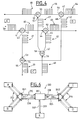
- Fig. 4 illustrates a branching apparatus for a branching unit having three branches A, B and C.
- the branching apparatus consists of six interconnected interleavers three of which are add interleavers and three of which are drop interleavers.
- the six interleavers are interconnected so as to form six distinct pairs of concatenated interleavers configured in the manner illustrated in Fig. 3.
- Each pair of concatenated interleavers comprises a first interleaver being a drop interleaver, and a second interleaver being an add interleaver.
- Each of the branches A, B and C of the branching unit have one optical input and one optical output each of which is connected to a respective optical input or output of a separate interleaver pair.
- the six distinct pairs of interleavers are the drop interleaver D1 with the add interleaver A1, the drop interleaver D2 with the add interleaver A2, the drop interleaver D1 with the add interleaver A3, the drop interleaver D3 with the add interleaver A1, the drop interleaver D3 with the add interleaver A2, and the drop interleaver D2 with the add interleaver A3.
- This pairing permits optical signals input at any one branch of the three branches A, B and C of the branching unit, to be separated in to two component portions which are then each separately combined with separated component portions of optical signals input at the other two optical inputs of the branching unit for subsequent output on a respective one output of the other two branches.
- Fig. 4 illustrates this process in operation in terms of a first optical signal 59 input at the optical input of branch A concurrently with a similar optical signal 64 input at branch B and a third similar optical signal 69 input at the optical input of branch C of the branching unit.
- Each one of these three signals consists of a string of DWDM optical channels, the string comprising even-numbered channels interleaved with odd-numbered channels.
- the optical signal 59 input at branch A of the branching unit is directed to the optical input 41 of drop interleaver D1 of the first and third interleaver pair.
- the drop interleaver D1 separates the input optical signal 59 in to the first portion comprising all of the even-numbered DWDM channels of the optical signal, and a second portion comprising all of the odd-numbered channels thereof.
- the first portion is output at the first optical output of the interleaver D1 for input to the first optical input port 44 of the add interleaver A1 of the first interleaver pair.
- the second portion 61 of the input optical signal 59 is output at the output port 43 of drop interleaver D1 for input to the first optical input port 53 of the add interleaver A3 of the third interleaver pair.
- optical signal 64 input at the optical input of branch B of the branching unit is directed to the optical input port 47 of the drop interleaver D2 of the second and sixth interleaver pair.
- This drop interleaver similarly separates the input optical signal 64 in to its component even-numbered and odd-numbered DWDM signals portions.
- the even-numbered channels 65 being output at the first optical output port 48 of this drop interleaver for input at the second optical input port of the add interleaver A3 of the sixth and third pairs of concatenated interleavers so as to be combined thereby with the separate group of even channels 61 input at the first input port 53 of add interleaver A3 so as to provide a combined optical signal 70 the output port 55 thereof.
- This combined signal is subsequently output on the output port of branch C of the branching unit.
- An optical signal 69 comprising interleaved even-numbered and odd-numbered DWDM channels input at branch C is directed to the input port 56 of drop interleaver D3 of the fourth and fifth interleaver pairs, the odd-numbered channels 62 being output at the first output port 57 thereof to the second input port 45 of add interleaver A1 of the fourth interleaver pair.
- the even numbered channels 67 of the optical signal are output at the second output port 58 of drop interleaver D3 and are directed to the second optical input port 51 of add interleaver A2 of the second and the fifth interleaver pairs.
- odd numbered channels 62 input to interleaver A1 are combined thereby with even numbered channels 60 concurrently input thereto so as to provide a combined optical output signal at output port 46 thereof comprising interleaved even and odd such signals.
- This combined signal is then directed to the optical output port of branch B of the branching unit.
- any DWDM optical signal input at a given one of the three branches of the branching unit will be separated in to its even-numbered and odd-numbered DWDM channel portions which portions will be subsequently output on different ones of the other two output ports of the branching unit in combination with odd-numbered and even-numbered channel portions of DWDM optical signals respectively input at the other two optical input ports of the branching unit.
- Fig. 5 illustrates branching apparatus of a branching unit comprising four distict groups of three concatenated interleavers. Each one of these interleaver triplets connects the optical input E of the branching unit with one of four optical output ports A, B, C, and D of the branching unit. Each interleaver triplet comprises an initial drop interleaver connected to an intermediate drop interleaver and terminating with a terminal add interleaver.
- the four distinct interleavers triplets illustrated in Fig. 5 include: a first interleaver triplet comprising initial drop interleaver D4 in combination with intermediate drop interleaver D5 and terminating with terminal add interleaver A4; a second triplet comprising an initial drop interleaver D4 combined with an intermediate drop interleaver D6 and terminating with terminal add interleaver A6; a third triplet comprising initial drop interleaver D4 in combination with intermediate drop interleaver D6 and terminating with terminal add interleaver A5; and finally, a fourth triplet comprising initial drop interleaver D4 in combination with intermediate drop interleaver D5 and terminating with terminal add interleaver A7.
- one optical output of the initial interleaver thereof is connected to the optical input port of the intermediate drop interleaver, and one optical output port of the intermediate drop interleaver is subsequently connected to one optical input port of the terminal add interleaver of the triplet.
- a DWDM optical signal 100 input at the optical input port 71 of the initial drop interleaver D4 of each of the four interleaver triplets is separated thereby in to component even-numbered and odd-numbered DWDM optical channels.
- the odd-numbered channels 101 are output at a first optical output port 73 of the drop interleaver D4 while the even-numbered channels 102 are output at the second optical output port 72 thereof.
- the odd-numbered optical channels 101 are subsequently directed to the optical input port of intermediate drop interleaver D5 of both the first and the fourth interleaver triplet, while the even-numbered channels 102 are directed to the optical input port 80 of the intermediate drop interleaver D6 of the second and the third interleaver triplets.
- the intermediate drop interleaver D5 separates the optical channels input thereto in to even-numbered and odd-numbered channels outputting the odd-numbered channels on the first optical output port 76 thereof whilst simultaneously outputting the even-numbered channels on the second optical output port 75 thereof.
- the intermediate drop interleaver D6 separates the optical signal 102 input thereto in to odd-numbered channels for output at a first optical output port 82 thereof, and even-numbered channels for output at optical output port 81 thereof.
- Even-numbered channels output by the intermediate drop interleaver D5 of the first interleaver triplet are directed to one optical input port 77 of the terminal add interleaver A4 of that triplet for combination with optical signals 107 concurrently input to the second optical input port 78 thereof.
- These combined signals are subsequently output at the optical output port 79 so as to provide combined signal 108 which is subsequently directed to the optical output port of branch D of the branching apparatus.
- odd-numbered channels output by intermediate drop interleaver D5 at output port 76 thereof are directed to an optical input port 89 of the terminal add interleaver A7 of the fourth interleaver triplet.
- Optical signals 113 concurrently input to the second optical input port 90 of terminal add interleaver A7 are combined thereby with the odd-numbered channels input thereto at the first optical input port 89 so as to provide at the optical output port 91 thereof a combined optical signal 114 for output at the optical output port A of the branching apparatus.
- even-numbered and odd-numbered optical channels input to terminal add interleavers A6 and A5 of the second and the third interleaver triplets respectively are combined with other optical signals input to those respective terminal add interleavers so as to provide combined optical signals for output at the optical output port B and C of the branching apparatus.
- optical signals may be directed in to the optical input of each initial drop interleaver of the four modified interleaver triplets from a respective one of the optical ports A, B, C or D of the branching apparatus.
- the intermediate and terminal add interleavers would then serve to combine the optical signals separately dropped by each of the four initial drop interleavers so as to provide a combined optical signal consisting of those four dropped portions for output at the optical port E of the modified branching apparatus.
- a branching unit having full interconnectivity between branch E and each of the other four branches A, B, C and D, of the branching unit.
- Fig. 6 illustrates an optical network using just such an optical branching unit.
- the optical network 200 comprises a submerged network node 201 within which is located the branching unit, the network node interconnecting terminal E with each one of four other terminal nodes A, B, C and D.
- Optical interconnection from terminal E to each one of the other four optical terminals is achieved via optical transmission line 202 which passes from terminal E to an optical input port of the branching unit located within the submerged network node 201, and via respective ones of the four optical output transmission lines 211, 206, 208 and 204 to respective terminals A, B, C and D.
- Optical branching apparatus of the form and configuration illustrated in Fig. 5 achieves this interconnectivity and allows optical signals output from terminal E to be separated in to four distinct portions each one of which is directed to a respective one of the other four connected terminals.
- the submerged network node 201 also includes modified optical branching apparatus as discussed above which permits optical signals input to the network node from terminals A, B, C or D, via optical transmission lines 210, 207, 209 and 205, to be combined by the modified branching apparatus as discussed above and output to the terminal E along optical transmission line 203.
- the optical network 200 also includes two full add and drop branching units BU1 and BU2, which permit direct add and drop interconnectivity between terminals A and B, and between terminals C and D respectively, by way of respective add and drop optical transmission line-pairs 215 and 220.
- the present invention may provide a branching unit which permits optical interconnectivity between branches thereof by way of a branching apparatus comprising a plurality of interconnected interleavers. It will be readily appreciated that pluralities of interleavers may be interconnected in ways other than illustrated and described in the present embodiments, without departing from the scope of the present invention.
Landscapes
- Engineering & Computer Science (AREA)
- Computer Networks & Wireless Communication (AREA)
- Signal Processing (AREA)
- Optical Communication System (AREA)
Applications Claiming Priority (2)
| Application Number | Priority Date | Filing Date | Title |
|---|---|---|---|
| GBGB0126168.4A GB0126168D0 (en) | 2001-10-31 | 2001-10-31 | A branching unit |
| GB0126168 | 2001-10-31 |
Publications (2)
| Publication Number | Publication Date |
|---|---|
| EP1309119A2 true EP1309119A2 (fr) | 2003-05-07 |
| EP1309119A3 EP1309119A3 (fr) | 2006-08-02 |
Family
ID=9924901
Family Applications (1)
| Application Number | Title | Priority Date | Filing Date |
|---|---|---|---|
| EP02292597A Withdrawn EP1309119A3 (fr) | 2001-10-31 | 2002-10-21 | Unité de branchement |
Country Status (4)
| Country | Link |
|---|---|
| US (1) | US6895142B2 (fr) |
| EP (1) | EP1309119A3 (fr) |
| JP (1) | JP2003198471A (fr) |
| GB (1) | GB0126168D0 (fr) |
Cited By (2)
| Publication number | Priority date | Publication date | Assignee | Title |
|---|---|---|---|---|
| EP1608098A1 (fr) * | 2004-06-16 | 2005-12-21 | Lucent Technologies Inc. | Multipléxeur optique à insertion-extraction avec une configuration de canal alternée |
| EP1608097A3 (fr) * | 2004-06-16 | 2006-03-22 | Lucent Technologies Inc. | Multiplexeur optique à insertion/extraction possédant une configuration de canaux à bandes |
Citations (1)
| Publication number | Priority date | Publication date | Assignee | Title |
|---|---|---|---|---|
| JPH05100254A (ja) * | 1991-10-07 | 1993-04-23 | Nippon Telegr & Teleph Corp <Ntt> | 光周波数分岐挿入回路 |
Family Cites Families (18)
| Publication number | Priority date | Publication date | Assignee | Title |
|---|---|---|---|---|
| US15836A (en) * | 1856-09-30 | Jambs wallace | ||
| GB2280279B (en) * | 1993-07-22 | 1996-06-26 | Northern Telecom Ltd | Branching unit for submarine telecommunications systems |
| JP3463717B2 (ja) * | 1995-08-24 | 2003-11-05 | 三菱電機株式会社 | 波長多重光伝送装置および波長多重光伝送システム |
| JPH09116490A (ja) * | 1995-10-16 | 1997-05-02 | Fujitsu Ltd | 光多重システム用分岐装置 |
| JPH1032562A (ja) | 1996-07-16 | 1998-02-03 | Fujitsu Ltd | 光アッド/ドロップ回路 |
| US5953141A (en) * | 1996-10-03 | 1999-09-14 | International Business Machines Corporation | Dynamic optical add-drop multiplexers and wavelength-routing networks with improved survivability and minimized spectral filtering |
| JPH11202374A (ja) * | 1998-01-14 | 1999-07-30 | Fujitsu Ltd | 波長多重システムにおける光通信端局、光信号伝送方法、及び光信号の増設方法 |
| FI990238A7 (fi) | 1999-02-08 | 2000-08-09 | Nokia Networks Oy | OptinenADd/drop-laite |
| US6215926B1 (en) * | 1999-02-10 | 2001-04-10 | Avanex Corporation | Fiber optic dense wavelength division multiplexer with a phase differential method of wavelengths separation utilizing glass blocks and a nonlinear interferometer |
| EP1030480A3 (fr) * | 1999-02-19 | 2002-06-12 | JDS Uniphase Inc. | Circuit optique configurable |
| GB2348557B (en) | 1999-04-01 | 2002-03-13 | Marconi Comm Ltd | Communications system |
| GB9919580D0 (en) * | 1999-08-18 | 1999-10-20 | Cit Alcatel | A landing stage for a submarine communications system |
| KR20010061613A (ko) | 1999-12-28 | 2001-07-07 | 윤종용 | 업그레이드 가능한 파장 분할 다중화 시스템의 노드 구조 |
| US6781754B2 (en) * | 2000-06-07 | 2004-08-24 | Cirvine Corporation | Interleaver using spatial birefringent elements |
| US6765775B2 (en) * | 2000-12-27 | 2004-07-20 | Pirelli Cavi E Sistemi S.P.A. | Submarine cable branching unit with current limiter |
| JP4588234B2 (ja) * | 2001-03-15 | 2010-11-24 | 富士通株式会社 | 光デバイス及びこれを用いる波長多重通信システム |
| JP3832274B2 (ja) * | 2001-05-14 | 2006-10-11 | 日本電気株式会社 | 波長補正方法、波長補正装置、波長検査方法、波長検査装置、アレイ導波路回折格子およびインタリーバ |
| US6724539B2 (en) * | 2001-11-02 | 2004-04-20 | Sumitomo Electric Industries, Ltd. | Interleaver |
-
2001
- 2001-10-31 GB GBGB0126168.4A patent/GB0126168D0/en not_active Ceased
-
2002
- 2002-10-21 EP EP02292597A patent/EP1309119A3/fr not_active Withdrawn
- 2002-10-25 JP JP2002311327A patent/JP2003198471A/ja active Pending
- 2002-10-28 US US10/281,322 patent/US6895142B2/en not_active Expired - Fee Related
Patent Citations (1)
| Publication number | Priority date | Publication date | Assignee | Title |
|---|---|---|---|---|
| JPH05100254A (ja) * | 1991-10-07 | 1993-04-23 | Nippon Telegr & Teleph Corp <Ntt> | 光周波数分岐挿入回路 |
Cited By (2)
| Publication number | Priority date | Publication date | Assignee | Title |
|---|---|---|---|---|
| EP1608098A1 (fr) * | 2004-06-16 | 2005-12-21 | Lucent Technologies Inc. | Multipléxeur optique à insertion-extraction avec une configuration de canal alternée |
| EP1608097A3 (fr) * | 2004-06-16 | 2006-03-22 | Lucent Technologies Inc. | Multiplexeur optique à insertion/extraction possédant une configuration de canaux à bandes |
Also Published As
| Publication number | Publication date |
|---|---|
| US6895142B2 (en) | 2005-05-17 |
| GB0126168D0 (en) | 2002-01-02 |
| JP2003198471A (ja) | 2003-07-11 |
| US20030091273A1 (en) | 2003-05-15 |
| EP1309119A3 (fr) | 2006-08-02 |
Similar Documents
| Publication | Publication Date | Title |
|---|---|---|
| EP0842574B1 (fr) | Multiplexeur a insertion-extraction | |
| CA2285128C (fr) | Commutateur pour signaux optiques | |
| JP5470379B2 (ja) | 光信号を切り換えるためのデバイス | |
| EP2255542B1 (fr) | Construction de grands commutateurs sélectifs de longueurs d'ondes en utilisant le parallélisme | |
| US20030210870A1 (en) | Switch for optical signals | |
| US20100061727A1 (en) | HITLESS MxN WAVELENGTH SELECTIVE SWITCH | |
| WO1997028475A1 (fr) | Dispositif de filtrage a longueurs d'onde multiples utilisant un reseau de bragg dans une fibre optique | |
| JP2001112034A (ja) | クロス接続交換機及びその実現方法 | |
| CA2220319C (fr) | Dispositif de multiplexage en longueur d'onde bidirectionnel hybride | |
| JP4739928B2 (ja) | 波長選択光スイッチおよび波長選択光スイッチモジュール | |
| US10256936B2 (en) | Method and apparatus for optical node construction using software programmable ROADMs | |
| JPH11513206A (ja) | 光ファイバネットワークの信号経路指定 | |
| US6956987B2 (en) | Planar lightwave wavelength blocker devices using micromachines | |
| US6859576B2 (en) | Optical cross-connect system | |
| US6895142B2 (en) | Branching unit | |
| US20140270634A1 (en) | Multi- purpose apparatus for switching, amplifying, replicating, and monitoring optical signals on a multiplicity of optical fibers | |
| US7113662B2 (en) | Optical filtering by using an add-drop node | |
| US6856719B2 (en) | Optical switch system | |
| US7298976B2 (en) | Bi-directional optical cross-connect device | |
| US20050276605A1 (en) | Method of upgrading an optical transmission network, an optical transmission network, and associated optical transmission nodes | |
| WO2001041333A1 (fr) | Demultiplexeur par repartition en longueur d'onde a bande etroite et procede de demultiplexage de signaux optiques | |
| US20040190896A1 (en) | Multi-directional optical branching apparatus | |
| CN2456381Y (zh) | 在分波多任务系统中的两种光信号交换模块架构 | |
| US10574380B2 (en) | Method and apparatus for optical node construction using software programmable ROADMs having N X M wavelength selective switches | |
| US7133612B1 (en) | Bidirectional WDM transmission system having transmission format for reducing adverse effects of filter concatonation |
Legal Events
| Date | Code | Title | Description |
|---|---|---|---|
| PUAI | Public reference made under article 153(3) epc to a published international application that has entered the european phase |
Free format text: ORIGINAL CODE: 0009012 |
|
| AK | Designated contracting states |
Designated state(s): AT BE BG CH CY CZ DE DK EE ES FI FR GB GR IE IT LI LU MC NL PT SE SK TR |
|
| AX | Request for extension of the european patent |
Extension state: AL LT LV MK RO SI |
|
| PUAL | Search report despatched |
Free format text: ORIGINAL CODE: 0009013 |
|
| AK | Designated contracting states |
Kind code of ref document: A3 Designated state(s): AT BE BG CH CY CZ DE DK EE ES FI FR GB GR IE IT LI LU MC NL PT SE SK TR |
|
| AX | Request for extension of the european patent |
Extension state: AL LT LV MK RO SI |
|
| 17P | Request for examination filed |
Effective date: 20061229 |
|
| RAP1 | Party data changed (applicant data changed or rights of an application transferred) |
Owner name: ALCATEL LUCENT |
|
| AKX | Designation fees paid |
Designated state(s): AT BE BG CH CY CZ DE DK EE ES FI FR GB GR IE IT LI LU MC NL PT SE SK TR |
|
| 17Q | First examination report despatched |
Effective date: 20091221 |
|
| RAP1 | Party data changed (applicant data changed or rights of an application transferred) |
Owner name: ALCATEL LUCENT |
|
| 111Z | Information provided on other rights and legal means of execution |
Free format text: AT BE BG CH CY CZ DE DK EE ES FI FR GB GR IE IT LI LU MC NL PT SE SK TR Effective date: 20130410 |
|
| STAA | Information on the status of an ep patent application or granted ep patent |
Free format text: STATUS: THE APPLICATION IS DEEMED TO BE WITHDRAWN |
|
| 18D | Application deemed to be withdrawn |
Effective date: 20130530 |