EP1309802B1 - Ventilblock und ventilblockeinsatz zum herstellen solch eines ventilblocks - Google Patents
Ventilblock und ventilblockeinsatz zum herstellen solch eines ventilblocks Download PDFInfo
- Publication number
- EP1309802B1 EP1309802B1 EP01957754A EP01957754A EP1309802B1 EP 1309802 B1 EP1309802 B1 EP 1309802B1 EP 01957754 A EP01957754 A EP 01957754A EP 01957754 A EP01957754 A EP 01957754A EP 1309802 B1 EP1309802 B1 EP 1309802B1
- Authority
- EP
- European Patent Office
- Prior art keywords
- pneumatic
- valve block
- valves
- connections
- block according
- Prior art date
- Legal status (The legal status is an assumption and is not a legal conclusion. Google has not performed a legal analysis and makes no representation as to the accuracy of the status listed.)
- Expired - Lifetime
Links
- 238000001746 injection moulding Methods 0.000 claims description 8
- 239000011347 resin Substances 0.000 claims description 3
- 229920005989 resin Polymers 0.000 claims description 3
- 238000013016 damping Methods 0.000 claims description 2
- 230000001419 dependent effect Effects 0.000 claims description 2
- 230000037431 insertion Effects 0.000 claims 1
- 238000003780 insertion Methods 0.000 claims 1
- 238000009429 electrical wiring Methods 0.000 description 5
- 238000010276 construction Methods 0.000 description 1
- 238000011161 development Methods 0.000 description 1
- 230000018109 developmental process Effects 0.000 description 1
- 238000010616 electrical installation Methods 0.000 description 1
- 238000004880 explosion Methods 0.000 description 1
- 210000003746 feather Anatomy 0.000 description 1
- 238000002347 injection Methods 0.000 description 1
- 239000007924 injection Substances 0.000 description 1
- 230000003993 interaction Effects 0.000 description 1
- 230000007257 malfunction Effects 0.000 description 1
- 238000004519 manufacturing process Methods 0.000 description 1
- 238000013021 overheating Methods 0.000 description 1
Images

Classifications
-
- F—MECHANICAL ENGINEERING; LIGHTING; HEATING; WEAPONS; BLASTING
- F15—FLUID-PRESSURE ACTUATORS; HYDRAULICS OR PNEUMATICS IN GENERAL
- F15B—SYSTEMS ACTING BY MEANS OF FLUIDS IN GENERAL; FLUID-PRESSURE ACTUATORS, e.g. SERVOMOTORS; DETAILS OF FLUID-PRESSURE SYSTEMS, NOT OTHERWISE PROVIDED FOR
- F15B13/00—Details of servomotor systems ; Valves for servomotor systems
- F15B13/02—Fluid distribution or supply devices characterised by their adaptation to the control of servomotors
- F15B13/06—Fluid distribution or supply devices characterised by their adaptation to the control of servomotors for use with two or more servomotors
- F15B13/08—Assemblies of units, each for the control of a single servomotor only
- F15B13/0803—Modular units
- F15B13/0807—Manifolds
- F15B13/081—Laminated constructions
-
- F—MECHANICAL ENGINEERING; LIGHTING; HEATING; WEAPONS; BLASTING
- F15—FLUID-PRESSURE ACTUATORS; HYDRAULICS OR PNEUMATICS IN GENERAL
- F15B—SYSTEMS ACTING BY MEANS OF FLUIDS IN GENERAL; FLUID-PRESSURE ACTUATORS, e.g. SERVOMOTORS; DETAILS OF FLUID-PRESSURE SYSTEMS, NOT OTHERWISE PROVIDED FOR
- F15B13/00—Details of servomotor systems ; Valves for servomotor systems
- F15B13/02—Fluid distribution or supply devices characterised by their adaptation to the control of servomotors
- F15B13/06—Fluid distribution or supply devices characterised by their adaptation to the control of servomotors for use with two or more servomotors
- F15B13/08—Assemblies of units, each for the control of a single servomotor only
- F15B13/0803—Modular units
- F15B13/0832—Modular valves
- F15B13/0842—Monoblock type valves, e.g. with multiple valve spools in a common housing
-
- F—MECHANICAL ENGINEERING; LIGHTING; HEATING; WEAPONS; BLASTING
- F15—FLUID-PRESSURE ACTUATORS; HYDRAULICS OR PNEUMATICS IN GENERAL
- F15B—SYSTEMS ACTING BY MEANS OF FLUIDS IN GENERAL; FLUID-PRESSURE ACTUATORS, e.g. SERVOMOTORS; DETAILS OF FLUID-PRESSURE SYSTEMS, NOT OTHERWISE PROVIDED FOR
- F15B13/00—Details of servomotor systems ; Valves for servomotor systems
- F15B13/02—Fluid distribution or supply devices characterised by their adaptation to the control of servomotors
- F15B13/06—Fluid distribution or supply devices characterised by their adaptation to the control of servomotors for use with two or more servomotors
- F15B13/08—Assemblies of units, each for the control of a single servomotor only
- F15B13/0803—Modular units
- F15B13/0846—Electrical details
- F15B13/0857—Electrical connecting means, e.g. plugs, sockets
-
- F—MECHANICAL ENGINEERING; LIGHTING; HEATING; WEAPONS; BLASTING
- F15—FLUID-PRESSURE ACTUATORS; HYDRAULICS OR PNEUMATICS IN GENERAL
- F15B—SYSTEMS ACTING BY MEANS OF FLUIDS IN GENERAL; FLUID-PRESSURE ACTUATORS, e.g. SERVOMOTORS; DETAILS OF FLUID-PRESSURE SYSTEMS, NOT OTHERWISE PROVIDED FOR
- F15B13/00—Details of servomotor systems ; Valves for servomotor systems
- F15B2013/002—Modular valves, i.e. consisting of an assembly of interchangeable components
- F15B2013/006—Modular components with multiple uses, e.g. kits for either normally-open or normally-closed valves, interchangeable or reprogrammable manifolds
-
- Y—GENERAL TAGGING OF NEW TECHNOLOGICAL DEVELOPMENTS; GENERAL TAGGING OF CROSS-SECTIONAL TECHNOLOGIES SPANNING OVER SEVERAL SECTIONS OF THE IPC; TECHNICAL SUBJECTS COVERED BY FORMER USPC CROSS-REFERENCE ART COLLECTIONS [XRACs] AND DIGESTS
- Y10—TECHNICAL SUBJECTS COVERED BY FORMER USPC
- Y10T—TECHNICAL SUBJECTS COVERED BY FORMER US CLASSIFICATION
- Y10T137/00—Fluid handling
- Y10T137/5109—Convertible
- Y10T137/5283—Units interchangeable between alternate locations
Definitions
- the invention relates to a valve block for at least two fixable in a housing Valves with electrical wiring to electrical connections for the valves and pneumatic cabling to pneumatic connections for the valves, as well as a valve block set for Producing such a valve block.
- valves some of which also have different functions meet in a higher-level unit such as motor vehicles. Disadvantageously, so far said valves are usually mounted individually, which in particular the assembly difficult and extended and thus the final price of the parent Unit increases.
- valve block is known from EP 0 686 239 B1, which is a Base plate with pneumatic cabling in the form of ducts for supply and exhaust air from Connection openings in a suitable for mounting special valves hole pattern a consumer and with an electrical wiring comprising one in the one to the pneumatic cabling parallel electrical duct placed electrical installation equipment.
- EP 0 686 239 B1 is a Base plate with pneumatic cabling in the form of ducts for supply and exhaust air from Connection openings in a suitable for mounting special valves hole pattern a consumer and with an electrical wiring comprising one in the one to the pneumatic cabling parallel electrical duct placed electrical installation equipment.
- Object of the present invention is therefore the known valve block such develop further that the disadvantages of the prior art are overcome, in particular Manufacturing and assembly costs, reduced and the scope is increased.
- the housing has a bottom part, preferably in the form of a Injection molding, for receiving the valves, wherein the bottom part of the electrical connector, the electrical wiring, the electrical connections, at least part of the pneumatic connector, at least part of the pneumatic cabling, preferably in the form of air supply openings and / or channels, and includes the pneumatic connections and with the Replacement insert firmly connectable or connected.
- Embodiments of the invention may be characterized in that the interchangeable insert Air supply openings and / or channels, which with a first cover, preferably from an injection-molded part, lockable, in particular ultrasonically weldable, are.
- the pneumatic cabling and / or the pneumatic connections may have air supply openings and / or channels each having a cross section of 1 to 6 mm x 1 to 6 mm, preferably 4 to 5 mm x 4 to 5 mm.
- ring seals can be provided on pneumatic interfaces.
- At least one check valve may be provided in the pneumatic cabling.
- the pneumatic connector comprises two pneumatic connector terminals, wherein a first pneumatic connector detachable and lockable to the second pneumatic connector, preferably Part of the injection molding of the bottom part is, in particular via a tongue and groove connection, attachable.
- the bottom part in particular the selectable Pneumatic plug connection and / or the removable insert, one of the valves and / or whose function has or have dependent coding.
- the electrical connector and the pneumatic connector facing each other Outside of the bottom part are arranged.
- the bottom part has at least one access opening for inserting the valves, and the interior of the bottom part with the arranged therein Valves is pourable, in particular with a resin, and / or with a second Lid, preferably from an injection molded part, closable, in particular latched, is.
- embodiments may be provided with a fastening means, in particular as part of the injection molding of the bottom part, and / or an attenuator, preferably in interaction with the fastener.
- valves in the housing via a plug connection are attached, preferably the pneumatic valve ports of the valves into the pneumatic ports in the form of air supply openings in the bottom part to the Replacement insert and / or the electrical connections in the form of protruding from the bottom part Contacts in openings to the electrical valve ports of the valves can be inserted.
- Three valves can be arranged in the housing of a valve block according to the invention be.
- valve block set for producing an inventive Valve block provided.
- valves on the one hand and the interchangeable inserts and / or the On the other hand have a coordinated coding, in dependence of which a valve block with a specific function can be produced.
- the invention is thus based on the surprising finding that several valves in a housing, preferably via a simple plug connection, are attachable, underneath simultaneous connection to a single electrical connector and a single pneumatic connector.
- the valve block according to the invention can then be easily and quickly in any parent Unit by connecting electrical cables to the single electrical connector and Fit air hoses to the single pneumatic connector.
- valves of the valve block by using a selectable interchangeable insert and a selectable pneumatic connector with special air inlet openings and / or channels in the valve block possible, so that so to speak standardized in the modular principle Valve blocks for different valves and / or functions from a valve block set can be produced to further simplify work.
- a variety of different pneumatic cabling of the valves of the valve block by using a selectable interchangeable insert and a selectable pneumatic connector with special air inlet openings and / or channels in the valve block possible so that so to speak standardized in the modular principle Valve blocks for different valves and / or functions from a valve block set can be produced to further simplify work.
- the combination variety of valves that can be used in a valve block according to the invention due the interchangeability of the interchangeable inserts and Pneumatiksteckeran somebody else. It is not only the use of different valves but also the fulfillment of different ones Functions due to the flexibility of the pneumatic cabling possible.
- an inventive valve block for use in a motor vehicle two electropneumatic converters one of which is for adjusting a vacuum actuator in an exhaust gas recirculation system and the other for controlling a vacuum actuator for a turbocharger control is used, and an electrical switching valve in the form of a 3/2-way valve for controlling a vacuum actuator for a parking flap, as in particular used in diesel engines include.
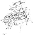
- an inventive valve block 1 comprises a Housing 2, which in turn has a bottom part 3.
- the bottom part 3 in turn includes one side a single electrical connector 4, via an electrical wiring, not shown is connected with protruding contacts 5, 5 'a as electrical connections, and at its the Electric plug 4 opposite side a single pneumatic connector 6a, 6b in operative connection with air supply openings 7a, 7'a, 7 "a.
- the pneumatic cabling between the trained in the form of two pneumatic connector terminals 6a, 6b pneumatic connector and the pneumatic ports representing air supply openings 7a, 7'a, 7 "a is in a changeover insert 8 in the form of air supply channels 8a, 8'a, 8 "a 3 centering 10 are provided in the bottom part.
- the bottom part 3 also mounting holes 11 for mounting in a parent unit, not shown on.
- valves 20 a, 20 b, 20 c can be inserted by inserting their pneumatic Valve terminals 21a, 21'a, 21 "a in the air supply openings 7a, 7'a, 7" a below simultaneous engagement of the contacts 5a, 5'a in not shown electrical valve connections.
- the two pneumatic plug connections 6a, 6b are connected via a tongue and groove connection 61, 62 releasably and lockably connectable to each other, wherein the outer pneumatic connector 6a has a plurality of hose connections 63.
- valve block 1 described with reference to Figures 1 and 2 in its structure can be Assemble as follows from a valve block set according to the invention:
- valves 20a, 20b, 20c and their pneumatic cabling in the form of the removable insert 8 according to a coding selected.
- the removable insert 8 is locked to the rest of the bottom part 3.
- the removable insert 8 is ultrasonically welded to a lid, not shown.
- valves 20a, 20b, 20c successively using the centering aid 10 in the bottom part 3 are inserted, so that there is an electrical contact between the Contacts 5a, 5'a and the electrical valve connections and a tight connection between the pneumatic valve ports 21a, 21'a, 21 “a and the Lunzu operationsötechnisch 7a, 7'a, 7 “a is coming.
- valves 20a, 20b, 20c are firmly inserted into the bottom part 3, the bottom part 3 with resin to improve the thermal conductivity, to protect against overheating and to increase the maximum duty cycle are poured out. Then another, not shown lid with the open end of the bottom part 3 are locked.
- valve block 1 can then by inserting screws, not shown in the mounting holes 11, in which additionally not shown rubber buffer for damping be screwed into a parent unit, such as a motor vehicle.
- an unshown electric cable can be connected to the electric plug 4.
- the outer pneumatic connector 6a are placed on the remaining valve block 1, wherein a corresponding placement is only possible if the inner pneumatic connector 6b selected according to the coding of the outer pneumatic connector 6a has been.
- the geometry of the pneumatic connector terminals 6a, 6b of a each coding depending on the function of the valve block 1 different be.
Landscapes
- Engineering & Computer Science (AREA)
- Physics & Mathematics (AREA)
- Fluid Mechanics (AREA)
- Mechanical Engineering (AREA)
- General Engineering & Computer Science (AREA)
- Valve Housings (AREA)
Description
- Fig. 1
- eine Teilexplosionsansicht eines erfindungsgemäßen Ventilblocks; und
- Fig. 2
- eine perspektivische Unteransicht des in Fig. 1 gezeigten Ventilblocks.
- 1
- Ventilblock
- 2
- Gehäuse
- 3
- Bodenteil
- 4
- Elektrostecker
- 5a, 5'a
- Kontakt
- 6a, 6b
- Pneumatiksteckeranschluß
- 7a, 7'a, 7"a
- Luftzuführungsöffnung
- 8
- Wechseleinsatz
- 8a, 8'a, 8"a
- Luftführungskanal
- 10
- Zentrierhilfe
- 11
- Befestigungsöffnung
- 20a, 20b, 20c
- Ventil
- 21a, 21'a, 21"a
- Ventilanschluß
- 61
- Nut
- 62
- Feder
- 63
- Schlauchanschluß
Claims (16)
- Ventilblock (1) mit einem Gehäuse (2) für zumindest zwei in dem Gehäuse (2) fixierbare Ventile (20a, 20b, 20c), mit einer Elektroverkabelung von einem Elektrostecker (4) zu Elektroanschlüssen (5a, 5'a) für die Ventile (20a, 20b, 20c) und einer Pneumatikverkabelung (8a, 8'a, 8"a) von einem Pneumatikstecker (6a, 6b) zu Pneumatikanschlüssen (7a, Ta, 7"a) für die Ventile (20a, 20b, 20c), sowie mit
einem in Abhängigkeit von den Ventilen (20a, 20b, 20c) und/oder deren Funktion auswählbaren Wechseleinsatz (8), durch welchen die Pneumatikverkabelung (8a, 8'a, 8"a) zumindest bereichsweise von dem Pneumatikstecker (6a, 6b), der zumindest einen in Abhängigkeit von den Ventilen (20a, 20b, 20c) und/oder deren Funktion auswählbaren Pneumatiksteckeranschluß (6b) aufweist, zu den Pneumatikanschlüssen (7a, 7'a, 7"a) der Ventile (20a, 20b, 20c) verläuft, wobei der auswählbare Wechseleinsatz (8) und der auswählbare Pneumatiksteckeranschluß (6b) mit dem Gehäuse (2) lösbar verbindbar sind. - Ventilblock nach Anspruch 1, dadurch gekennzeichnet, daß
das Gehäuse (2) ein Bodenteil (3), vorzugsweise in Form eines Spritzgußteils, zur Aufnahme der Ventile (20a, 20b, 20c) aufweist, wobei das Bodenteil (3) den Elektrostecker (4), die Elektroverkabelung, die Elektroanschlüsse (5a, 5'a), zumindest einen Teil des Pneumatiksteckers (6b), zumindest einen Teil der Pneumatikverkabelung, vorzugsweise in Form von Luftzuführungsöffnungen und/oder -kanälen, und die Pneumatikanschlüsse (7a, 7'a, 7"a) umfaßt sowie mit dem Wechseleinsatz (8) fest verbindbar bzw. verbunden ist. - Ventilblock nach Anspruch 1 oder 2, dadurch gekennzeichnet, daß
der Wechseleinsatz (8) Luftzuführungsöffnungen und/oder -kanäle (8a, 8'a, 8"a) aufweist, die mit einem ersten Deckel, vorzugsweise aus einem Spritzgußteil, verschließbar, insbesondere ultraschallverschweißbar, sind. - Ventilblock nach einem der vorangehenden Ansprüche, dadurch gekennzeichnet, daß der Wechseleinsatz (8) auf der Außenseite eines Bereichs des Bodenteils (3) und die Ventile (20a, 20b, 20c) auf der Innenseite besagten Bereichs des Bodenteils (3) angeordnet sind.
- Ventilblock nach einem der vorangehenden Ansprüche, dadurch gekennzeichnet, daß die Pneumatikverkabelung und/oder die Pneumatikanschlüsse Luftzuführungsöffnungen und/oder -kanäle (7a, 7'a, 7"a, 8a, 8'a, 8"a) mit jeweils einem Querschnitt von 1 bis 6 mm x 1 bis 6 mm, vorzugsweise 4 bis 5 mm x 4 bis 5 mm, aufweist bzw. aufweisen.
- Ventilblock nach einem der vorangehenden Ansprüche, gekennzeichnet durch Ringdichtungen an Pneumatikschnittstellen.
- Ventilblock nach einem der vorangehenden Ansprüche, gekennzeichnet durch zumindest ein Rückschlagventil in der Pneumatikverkabelung.
- Ventilblock nach einem der vorangehenden Ansprüche, dadurch gekennzeichnet, daß der Pneumatikstecker zwei Pneumatiksteckeranschlüsse (6a, 6b) umfaßt, wobei ein erster Pneumatiksteckeranschluß (6a) lösbar sowie arretierbar an den zweiten Pneumatiksteckeranschluß (6b), der vorzugsweise Bestandteil des Spritzgußteils des Bodenteils (3) ist, insbesondere über eine Nut/Feder-Verbindung (61, 62), anbringbar ist.
- Ventilblock nach einem der vorangehenden Ansprüche, dadurch gekennzeichnet, daß das Bodenteil (3), insbesondere jeder auswählbare Pneumatiksteckeranschluß (6a, 6b) und/oder der auswählbare Wechseleinsatz (8), eine von den Ventilen (20a, 20b, 20c) und/oder deren Funktion abhängige Kodierung aufweist bzw. aufweisen.
- Ventilblock nach einem der vorangehenden Ansprüche, dadurch gekennzeichnet, daß der Elektrostecker (4) und der Pneumatikstecker (6a, 6b) auf sich gegenüberliegenden Außenseiten des Bodenteils (3) angeordnet sind.
- Ventilblock nach einem der vorangehenden Ansprüche, dadurch gekennzeichnet, daß
das Bodenteil (3) zumindest eine Zugangsöffnung zum Einsetzen der Ventile (20a, 20b, 20c) aufweist, und das Innere des Bodenteils (3) mit den darin angeordneten Ventilen (20a, 20b, 20c) ausgießbar ist, insbesondere mit einem Harz, und/oder mit einem zweiten Deckel, vorzugsweise aus einem Spritzgußteil, verschließbar, insbesondere verrastbar, ist. - Ventilblock nach einem der vorangehenden Ansprüche, gekennzeichnet durch zumindest eine Zentrierhilfe (10) im Bodenteil (3) für jedes Ventil (20a, 20b, 20c).
- Ventilblock nach einem der vorangehenden Ansprüche, gekennzeichnet durch
ein Befestigungsmittel (11), insbesondere als Bestandteil des Spritzgußteils des Bodenteils (3), und/oder
ein Dämpfungsglied, vorzugsweise in Wechselwirkung mit dem Befestigungsmittel. - Ventilblock nach einem der vorangehenden Ansprüche, dadurch gekennzeichnet, daß die Ventile (20a, 20b, 20c) in dem Gehäuse (2) über eine Steckverbindung angebracht sind, wobei vorzugsweise die pneumatischenVentilanschlüsse (21, 21'a, 21"a) der Ventile (20a, 20b, 20c) in die Pneumatikanschlüsse in Form von Luftzuführungsöffnungen (7a, 7'a, 7"a) in dem Bodenteil (3) zu dem Wechseleinsatz (8) und/oder die Elektroanschlüsse in Form von von dem Bodenteil (3) abstehenden Kontakten (5a, 5'a) in Öffnungen zu den elektrischen Ventilanschlüssen der Ventile (20a, 20b, 20c) einsteckbar sind.
- Ventilblock nach einem der vorangehenden Ansprüche, dadurch gekennzeichnet, daß drei Ventile (20a, 20b, 20c) in dem Gehäuse (2) angeordnet sind.
- Ventilblocksatz bestehend aus einem Gehäuse mit einem Elektrostecker, einem Pneumatikstecker, Elektroanschlüssen sowie Pneumatikanschlüssen für Ventile, einem Satz auswählbarer Wechseleinsätze, einem Satz auswechselbarer Pneumatiksteckeranschlüsse und einem Satz Ventile,
zum Herstellen eines Ventilblocks nach einem der vorangehenden Ansprüche, dadurch gekennzeichnet, daß
die Ventile einerseits und die Wechseleinsätze und die Pneumatiksteckeranschlüsse andererseits eine aufeinander abgestimmte Kodierung aufweisen, in deren Abhängigkeit ein Ventilblock mit einer bestimmten Funktion herstellbar ist.
Applications Claiming Priority (3)
| Application Number | Priority Date | Filing Date | Title |
|---|---|---|---|
| DE10040559A DE10040559C2 (de) | 2000-08-15 | 2000-08-15 | Ventilblock und Ventilblocksatz zum Herstellen solch eines Ventilblocks |
| DE10040559 | 2000-08-15 | ||
| PCT/DE2001/002949 WO2002014697A1 (de) | 2000-08-15 | 2001-08-01 | Ventilblock und ventilblockeinsatz zum herstellen solch eines ventilblocks |
Publications (2)
| Publication Number | Publication Date |
|---|---|
| EP1309802A1 EP1309802A1 (de) | 2003-05-14 |
| EP1309802B1 true EP1309802B1 (de) | 2005-02-23 |
Family
ID=7652970
Family Applications (1)
| Application Number | Title | Priority Date | Filing Date |
|---|---|---|---|
| EP01957754A Expired - Lifetime EP1309802B1 (de) | 2000-08-15 | 2001-08-01 | Ventilblock und ventilblockeinsatz zum herstellen solch eines ventilblocks |
Country Status (6)
| Country | Link |
|---|---|
| US (1) | US6820634B2 (de) |
| EP (1) | EP1309802B1 (de) |
| JP (1) | JP2004506853A (de) |
| DE (2) | DE10040559C2 (de) |
| ES (1) | ES2238464T3 (de) |
| WO (1) | WO2002014697A1 (de) |
Cited By (1)
| Publication number | Priority date | Publication date | Assignee | Title |
|---|---|---|---|---|
| CN107407301A (zh) * | 2015-04-01 | 2017-11-28 | 山特维克知识产权股份有限公司 | 用于采矿机械的控制单元 |
Families Citing this family (12)
| Publication number | Priority date | Publication date | Assignee | Title |
|---|---|---|---|---|
| US7108868B2 (en) | 2002-03-22 | 2006-09-19 | Unigen Pharmaceuticals, Inc. | Isolation of a dual cox-2 and 5-lipoxygenase inhibitor from acacia |
| DE10301964B4 (de) * | 2003-01-20 | 2006-12-28 | Siemens Ag | Bauteil zur Aufnahme eines Ventils sowie Verfahren zur Herstellung hierfür |
| DE10328221B4 (de) * | 2003-06-24 | 2006-06-14 | Sauer-Danfoss Aps | Elektromagnetischer Ventilantrieb |
| KR100783211B1 (ko) * | 2006-07-19 | 2007-12-06 | 엘지전자 주식회사 | 냉장고의 냉매 누설 방지용 밸브 어셈블리 |
| KR100761248B1 (ko) * | 2006-10-12 | 2007-10-04 | 주식회사 유니젠 | 대나무 및 황금 추출물을 유효성분으로 함유하는 아토피성피부염 치료를 위한 조성물 |
| DE102006060923A1 (de) * | 2006-12-20 | 2008-06-26 | Testo Ag | Ventilblock |
| DE102007015656B4 (de) * | 2007-03-31 | 2009-11-05 | Festo Ag & Co. Kg | Fluidtechnische Anordnung |
| DE502007002698D1 (de) * | 2007-11-24 | 2010-03-11 | Festo Ag & Co Kg | Schaltschrank mit interner Ventilanordnung |
| DE102008011171A1 (de) * | 2008-02-26 | 2009-08-27 | Bonn, Georg, Dipl.-Ing. | Ventilblock für Hauskläranlagen |
| CN102203476B (zh) * | 2008-11-05 | 2014-11-12 | 诺格伦有限责任公司 | 模块化阀组件 |
| DE102020201428A1 (de) | 2020-02-06 | 2021-08-12 | Alfmeier Präzision SE | Verbindungselement und Versorgungsleiste für eine Ventilanordnung |
| DE102022214043B4 (de) * | 2022-12-20 | 2025-07-03 | Zf Friedrichshafen Ag | Verfahren zur Montage eines Ventilbehälters, Ventilbehälter, Betätigungsanordnung sowie Kraftfahrzeug |
Family Cites Families (15)
| Publication number | Priority date | Publication date | Assignee | Title |
|---|---|---|---|---|
| AT250116B (de) | 1963-06-07 | 1966-10-25 | Festo Maschf Stoll G | Ventilanordnung |
| FR2250907A1 (en) * | 1973-11-09 | 1975-06-06 | Bouteille Daniel | Assembly baseplates for pneumatic or hydraulic distributors - tongue and groove are standard modules which connect with into rigid block |
| DE3238750C1 (de) | 1982-10-20 | 1988-03-03 | Festo-Maschinenfabrik Gottlieb Stoll, 7300 Esslingen | Schaltkarte |
| IT8422711U1 (it) | 1984-07-27 | 1986-01-27 | Migliori Luciano | Sottobase per l'alimentazione ed il sostegno di valvole di comando. |
| DE3525857A1 (de) * | 1985-07-19 | 1987-02-05 | Festo Kg | Ventilanordnung |
| FR2592432B1 (fr) | 1985-12-30 | 1988-02-05 | Snecma | Regulateur, notamment pour turbomachine, a interface electrohydraulique a montage rapide |
| DE3729216A1 (de) * | 1987-09-02 | 1989-03-16 | Teves Gmbh Alfred | Hydraulikaggregat |
| DE4111893C2 (de) | 1991-04-09 | 1995-04-13 | Mannesmann Ag | Ventil-Grundplatte, insbesondere für gasförmige Medien |
| DE4305608A1 (de) * | 1993-02-24 | 1994-08-25 | Bosch Gmbh Robert | Ventilblock |
| DE4318420A1 (de) * | 1993-06-03 | 1994-12-08 | Bosch Gmbh Robert | Ventilblockaggregat |
| DE4402735A1 (de) | 1994-01-29 | 1995-08-03 | Teves Gmbh Alfred | Elektrohydraulische Druckregelvorrichtung |
| JP3774800B2 (ja) | 1997-09-24 | 2006-05-17 | 株式会社フジキン | 下段部材の固定装置およびこれを備えた流体制御装置 |
| US6053198A (en) * | 1997-12-01 | 2000-04-25 | Numatics, Incorporated | Solenoid valve control system |
| US6148862A (en) * | 1998-03-27 | 2000-11-21 | Applied Power Inc. | Solenoid valve coil pack |
| US6354674B1 (en) | 1998-12-11 | 2002-03-12 | Denso Corporation | Hydraulic control apparatus integrated with motor driving circuit unit |
-
2000
- 2000-08-15 DE DE10040559A patent/DE10040559C2/de not_active Expired - Lifetime
-
2001
- 2001-08-01 EP EP01957754A patent/EP1309802B1/de not_active Expired - Lifetime
- 2001-08-01 DE DE50105428T patent/DE50105428D1/de not_active Expired - Lifetime
- 2001-08-01 US US10/312,746 patent/US6820634B2/en not_active Expired - Fee Related
- 2001-08-01 ES ES01957754T patent/ES2238464T3/es not_active Expired - Lifetime
- 2001-08-01 WO PCT/DE2001/002949 patent/WO2002014697A1/de not_active Ceased
- 2001-08-01 JP JP2002519803A patent/JP2004506853A/ja active Pending
Cited By (2)
| Publication number | Priority date | Publication date | Assignee | Title |
|---|---|---|---|---|
| CN107407301A (zh) * | 2015-04-01 | 2017-11-28 | 山特维克知识产权股份有限公司 | 用于采矿机械的控制单元 |
| CN107407301B (zh) * | 2015-04-01 | 2021-05-07 | 山特维克知识产权股份有限公司 | 用于采矿机械的控制单元 |
Also Published As
| Publication number | Publication date |
|---|---|
| DE10040559A1 (de) | 2002-03-07 |
| EP1309802A1 (de) | 2003-05-14 |
| US6820634B2 (en) | 2004-11-23 |
| JP2004506853A (ja) | 2004-03-04 |
| ES2238464T3 (es) | 2005-09-01 |
| US20030102030A1 (en) | 2003-06-05 |
| DE50105428D1 (de) | 2005-03-31 |
| WO2002014697B1 (de) | 2002-07-25 |
| WO2002014697A1 (de) | 2002-02-21 |
| DE10040559C2 (de) | 2003-04-30 |
Similar Documents
| Publication | Publication Date | Title |
|---|---|---|
| DE112005003834B4 (de) | Verfahren und Vorrichtung zum Einstellen einer Öffneröffnung für einen Drosselkörper | |
| DE10040559C2 (de) | Ventilblock und Ventilblocksatz zum Herstellen solch eines Ventilblocks | |
| DE3730571A1 (de) | Vorrichtung zur halterung, kraftstoffversorgung und elektrischen kontaktierung von elektromagnetisch betaetigbaren kraftstoffeinspritzventilen | |
| DE19534285A1 (de) | Elektromagnetisch betätigbares pneumatisches Wegeventil | |
| DE102017103197A1 (de) | Elektronikgehäuse für einen E-Achsen-Antrieb und E-Achse mit Elektronikgehäuse | |
| DE4133641B4 (de) | Elektrohydraulische Druckregelvorrichtung | |
| DE102009019721A1 (de) | Hydraulisches System | |
| DE10314781A1 (de) | Modulare Kraftstoffeinspritzeinheit | |
| DE10148059A1 (de) | Nockenwellenverstellvorrichtung für eine Brennkraftmaschine | |
| EP1763917B1 (de) | Gehäuseteil für eine antriebseinheit, sowie verfahren und werkzeug zur herstellung eines solchen | |
| EP0918197B1 (de) | Baueinheit für eine Kompaktheizungsanlage | |
| EP1870199B1 (de) | Mehrachsendrehkopf für eine Werkzeugmaschine | |
| DE202007012369U1 (de) | Steckersystem | |
| DE4219679C1 (de) | Ventilanordnung | |
| DE69824984T2 (de) | Schutzgehäuse für eine Leiterplatte | |
| EP1526288A1 (de) | Pneumatische Ventilanordnung mit einem Kanaltrennelement | |
| EP1579153A1 (de) | Lüftergehäuse | |
| DE29516247U1 (de) | Steuerkopf für Armaturen mit pneumatischem Antrieb für die Lebensmittel- und Getränkeindustrie | |
| DE3927637C1 (de) | Magnetventil | |
| EP1526041B1 (de) | Steckverbinder für elektrische Leitungen in einem Fahrzeug | |
| EP0921927A1 (de) | Verfahren zur herstellung eines dichten kunststoffgehäuses | |
| EP0864817B1 (de) | Anschlussverkleidung für Heizkörper-Vor- und/oder Rücklaufanschlüsse | |
| EP1316748A2 (de) | Ventileinheit mit einem geräuscharmen Entlüftungskanal | |
| DE202005009954U1 (de) | Ventileinheit mit einem Ventilgrundkörper zur Aufnahme von Ventilen | |
| EP1306597B2 (de) | Ventil |
Legal Events
| Date | Code | Title | Description |
|---|---|---|---|
| PUAI | Public reference made under article 153(3) epc to a published international application that has entered the european phase |
Free format text: ORIGINAL CODE: 0009012 |
|
| 17P | Request for examination filed |
Effective date: 20021010 |
|
| AK | Designated contracting states |
Designated state(s): AT BE CH CY DE DK ES FI FR GB GR IE IT LI LU MC NL PT SE TR |
|
| RAP1 | Party data changed (applicant data changed or rights of an application transferred) |
Owner name: VOLKSWAGEN AG Owner name: WOCO INDUSTRIETECHNIK GMBH |
|
| RBV | Designated contracting states (corrected) |
Designated state(s): AT BE CH DE ES FR LI |
|
| GRAP | Despatch of communication of intention to grant a patent |
Free format text: ORIGINAL CODE: EPIDOSNIGR1 |
|
| RBV | Designated contracting states (corrected) |
Designated state(s): DE ES FR |
|
| GRAS | Grant fee paid |
Free format text: ORIGINAL CODE: EPIDOSNIGR3 |
|
| GRAA | (expected) grant |
Free format text: ORIGINAL CODE: 0009210 |
|
| AK | Designated contracting states |
Kind code of ref document: B1 Designated state(s): DE ES FR |
|
| REG | Reference to a national code |
Ref country code: IE Ref legal event code: FG4D Free format text: GERMAN |
|
| REF | Corresponds to: |
Ref document number: 50105428 Country of ref document: DE Date of ref document: 20050331 Kind code of ref document: P |
|
| REG | Reference to a national code |
Ref country code: ES Ref legal event code: FG2A Ref document number: 2238464 Country of ref document: ES Kind code of ref document: T3 |
|
| PLBE | No opposition filed within time limit |
Free format text: ORIGINAL CODE: 0009261 |
|
| STAA | Information on the status of an ep patent application or granted ep patent |
Free format text: STATUS: NO OPPOSITION FILED WITHIN TIME LIMIT |
|
| ET | Fr: translation filed | ||
| 26N | No opposition filed |
Effective date: 20051124 |
|
| REG | Reference to a national code |
Ref country code: FR Ref legal event code: PLFP Year of fee payment: 15 |
|
| PGFP | Annual fee paid to national office [announced via postgrant information from national office to epo] |
Ref country code: DE Payment date: 20150821 Year of fee payment: 15 Ref country code: ES Payment date: 20150827 Year of fee payment: 15 |
|
| PGFP | Annual fee paid to national office [announced via postgrant information from national office to epo] |
Ref country code: FR Payment date: 20150820 Year of fee payment: 15 |
|
| REG | Reference to a national code |
Ref country code: DE Ref legal event code: R119 Ref document number: 50105428 Country of ref document: DE |
|
| REG | Reference to a national code |
Ref country code: FR Ref legal event code: ST Effective date: 20170428 |
|
| PG25 | Lapsed in a contracting state [announced via postgrant information from national office to epo] |
Ref country code: FR Free format text: LAPSE BECAUSE OF NON-PAYMENT OF DUE FEES Effective date: 20160831 Ref country code: DE Free format text: LAPSE BECAUSE OF NON-PAYMENT OF DUE FEES Effective date: 20170301 |
|
| PG25 | Lapsed in a contracting state [announced via postgrant information from national office to epo] |
Ref country code: ES Free format text: LAPSE BECAUSE OF NON-PAYMENT OF DUE FEES Effective date: 20160802 |
|
| REG | Reference to a national code |
Ref country code: ES Ref legal event code: FD2A Effective date: 20180627 |