EP1309846B1 - Dispositif support pour une preparation permettant la separation par irradiation laser d'objets individuels contenus dans ladite preparation - Google Patents
Dispositif support pour une preparation permettant la separation par irradiation laser d'objets individuels contenus dans ladite preparation Download PDFInfo
- Publication number
- EP1309846B1 EP1309846B1 EP01974196A EP01974196A EP1309846B1 EP 1309846 B1 EP1309846 B1 EP 1309846B1 EP 01974196 A EP01974196 A EP 01974196A EP 01974196 A EP01974196 A EP 01974196A EP 1309846 B1 EP1309846 B1 EP 1309846B1
- Authority
- EP
- European Patent Office
- Prior art keywords
- membrane
- support device
- laser light
- laser
- light absorbent
- Prior art date
- Legal status (The legal status is an assumption and is not a legal conclusion. Google has not performed a legal analysis and makes no representation as to the accuracy of the status listed.)
- Expired - Lifetime
Links
- 238000002360 preparation method Methods 0.000 title claims abstract description 34
- 238000000926 separation method Methods 0.000 title description 4
- 239000012528 membrane Substances 0.000 claims abstract description 160
- 229920000728 polyester Polymers 0.000 claims abstract description 9
- 230000002745 absorbent Effects 0.000 claims abstract 17
- 239000002250 absorbent Substances 0.000 claims abstract 17
- 230000000717 retained effect Effects 0.000 claims abstract 2
- 239000002390 adhesive tape Substances 0.000 claims description 8
- 238000004113 cell culture Methods 0.000 claims description 8
- 239000000853 adhesive Substances 0.000 claims description 7
- 230000001070 adhesive effect Effects 0.000 claims description 7
- 239000004809 Teflon Substances 0.000 claims description 4
- 229920006362 Teflon® Polymers 0.000 claims description 4
- 239000011521 glass Substances 0.000 abstract description 24
- 239000012620 biological material Substances 0.000 abstract description 20
- 238000012545 processing Methods 0.000 abstract description 4
- 230000005855 radiation Effects 0.000 description 11
- 210000004027 cell Anatomy 0.000 description 9
- 238000005520 cutting process Methods 0.000 description 9
- 238000000034 method Methods 0.000 description 9
- 210000000349 chromosome Anatomy 0.000 description 7
- 238000013532 laser treatment Methods 0.000 description 6
- 238000002679 ablation Methods 0.000 description 5
- 239000007788 liquid Substances 0.000 description 5
- 239000000126 substance Substances 0.000 description 5
- -1 polyethylene naphthalene Polymers 0.000 description 3
- 239000000758 substrate Substances 0.000 description 3
- VYPSYNLAJGMNEJ-UHFFFAOYSA-N Silicium dioxide Chemical compound O=[Si]=O VYPSYNLAJGMNEJ-UHFFFAOYSA-N 0.000 description 2
- 238000002474 experimental method Methods 0.000 description 2
- 239000000463 material Substances 0.000 description 2
- 238000001531 micro-dissection Methods 0.000 description 2
- 239000004033 plastic Substances 0.000 description 2
- 229920003023 plastic Polymers 0.000 description 2
- 239000013464 silicone adhesive Substances 0.000 description 2
- 210000001519 tissue Anatomy 0.000 description 2
- LFQSCWFLJHTTHZ-UHFFFAOYSA-N Ethanol Chemical compound CCO LFQSCWFLJHTTHZ-UHFFFAOYSA-N 0.000 description 1
- 238000013459 approach Methods 0.000 description 1
- 239000007864 aqueous solution Substances 0.000 description 1
- 239000012876 carrier material Substances 0.000 description 1
- 210000003850 cellular structure Anatomy 0.000 description 1
- 238000013461 design Methods 0.000 description 1
- 238000000605 extraction Methods 0.000 description 1
- 239000012530 fluid Substances 0.000 description 1
- 238000011835 investigation Methods 0.000 description 1
- 238000001001 laser micro-dissection Methods 0.000 description 1
- 230000000873 masking effect Effects 0.000 description 1
- 239000002184 metal Substances 0.000 description 1
- 238000000386 microscopy Methods 0.000 description 1
- 230000003287 optical effect Effects 0.000 description 1
- 239000000377 silicon dioxide Substances 0.000 description 1
- 239000007787 solid Substances 0.000 description 1
- 229910001220 stainless steel Inorganic materials 0.000 description 1
- 239000010935 stainless steel Substances 0.000 description 1
- 239000013589 supplement Substances 0.000 description 1
- XLYOFNOQVPJJNP-UHFFFAOYSA-N water Substances O XLYOFNOQVPJJNP-UHFFFAOYSA-N 0.000 description 1
Images

Classifications
-
- G—PHYSICS
- G01—MEASURING; TESTING
- G01N—INVESTIGATING OR ANALYSING MATERIALS BY DETERMINING THEIR CHEMICAL OR PHYSICAL PROPERTIES
- G01N1/00—Sampling; Preparing specimens for investigation
- G01N1/28—Preparing specimens for investigation including physical details of (bio-)chemical methods covered elsewhere, e.g. G01N33/50, C12Q
-
- G—PHYSICS
- G01—MEASURING; TESTING
- G01N—INVESTIGATING OR ANALYSING MATERIALS BY DETERMINING THEIR CHEMICAL OR PHYSICAL PROPERTIES
- G01N1/00—Sampling; Preparing specimens for investigation
- G01N1/02—Devices for withdrawing samples
- G01N1/04—Devices for withdrawing samples in the solid state, e.g. by cutting
-
- G—PHYSICS
- G01—MEASURING; TESTING
- G01N—INVESTIGATING OR ANALYSING MATERIALS BY DETERMINING THEIR CHEMICAL OR PHYSICAL PROPERTIES
- G01N1/00—Sampling; Preparing specimens for investigation
- G01N1/28—Preparing specimens for investigation including physical details of (bio-)chemical methods covered elsewhere, e.g. G01N33/50, C12Q
- G01N1/2813—Producing thin layers of samples on a substrate, e.g. smearing, spinning-on
-
- G—PHYSICS
- G01—MEASURING; TESTING
- G01N—INVESTIGATING OR ANALYSING MATERIALS BY DETERMINING THEIR CHEMICAL OR PHYSICAL PROPERTIES
- G01N1/00—Sampling; Preparing specimens for investigation
- G01N1/02—Devices for withdrawing samples
- G01N1/04—Devices for withdrawing samples in the solid state, e.g. by cutting
- G01N2001/045—Laser ablation; Microwave vaporisation
-
- G—PHYSICS
- G01—MEASURING; TESTING
- G01N—INVESTIGATING OR ANALYSING MATERIALS BY DETERMINING THEIR CHEMICAL OR PHYSICAL PROPERTIES
- G01N1/00—Sampling; Preparing specimens for investigation
- G01N1/28—Preparing specimens for investigation including physical details of (bio-)chemical methods covered elsewhere, e.g. G01N33/50, C12Q
- G01N1/2813—Producing thin layers of samples on a substrate, e.g. smearing, spinning-on
- G01N2001/2833—Collecting samples on a sticky, tacky, adhesive surface
- G01N2001/284—Collecting samples on a sticky, tacky, adhesive surface using local activation of adhesive, i.e. Laser Capture Microdissection
Definitions
- the present invention relates to a carrier device for a preparation, in particular a biological preparation, which is suitable for removing individual objects contained in the preparation, in particular biological objects such as cells or chromosomes, from the preparation by means of laser radiation and thus separating them from the preparation.
- Generic carrier devices are used, for example, in the field of microdissection for sorting and obtaining individual biological cells.
- a corresponding method is described, for example, in WO 97/29355 A of the Applicant.
- it is proposed to separate a selected biological object from the surrounding biological mass located on a planar support by a laser beam, so that the selected biological object is freely prepared from the surrounding biological mass.
- the selected biological object is cut out of the surrounding biological mass by means of laser radiation.
- the thus freely prepared biological object is then catapulted by means of a laser shot from the carrier to a collecting device, wherein the collecting device may be, for example, a collecting substrate or a collecting cap ("cap").
- this method is used in combination with a corresponding microscope arrangement in order to be able to control the cutting and catapulting process under the microscope.
- the control of the laser beam for cutting out and / orfitkatapult Schl a selected biological object can be computerized.
- a single biological object is not necessarily required that first a cutting operation and then a catapulting using two separate laser irradiations is performed, but studies have shown that depending on the laser energy and the laser focus and the nature of each Even a single laser shot can be enough to treat biological material to dissolve the desired biological object directly from the surrounding biological mass and catapult into the catcher.
- the preparation to be processed with the laser radiation is usually located on a glass slide. However, it can also be located on a carrier membrane which absorbs the respective laser light and which is cut along with the preparation in the course of the cutting process.
- the freely prepared biological object is catapulted into the collecting device together with the corresponding excised membrane part.
- the use of such a support membrane is advantageous because it allows larger objects to be catapulted out in their entirety with individual laser shots, wherein the support membrane acts like a tray with which even larger areas can be transported or catapulted. Smaller biological objects, such as filaments or chromosomes, are easier to prepare freely, as they remain attached to the support membrane and can then catapulted morphologically intact into the catcher in the catapulting together with the corresponding membrane part.
- a support membrane is a is very thin membrane with a thickness in the micrometer range.
- a laser light transmissive carrier must be used to support the membrane or in support of the membrane.
- a glass slide is conventionally used, as it is used in known microscopes or the like. The application of the membrane to the glass slide is then usually done by hand, ie the membrane is placed by the respective user on the glass slide and optionally attached by attaching a special adhesive between the membrane and glass slides on the glass slide.
- EP-A-0 926 480 In connection with a device for handling samples for membrane-supported microdissection, it is proposed in EP-A-0 926 480 to hold a laser-light-absorbing membrane from a frame, so that the membrane is taut and thus easy to handle. In addition to this laser-light-absorbing membrane, it is proposed to use a further cover membrane. However, this exercises no support or support function on the laser light-absorbing membrane.
- a holding device or a retaining means is provided in order to tension the laser-light-absorbing membrane and thus to solve the above-described problem of waviness.
- the membrane which serves for receiving the preparation to be processed by means of laser radiation, can rest on a carrier, wherein the holding means is designed to hold the membrane and the carrier together.
- the membrane and the support means i. the membrane and the carrier are provided in the form of a "package", which facilitates the handling of the entire carrier device.
- the support means may, for example, be conventional laser-transparent slides, in particular made of glass, wherein the holding means are configured, for example, in the form of an in particular circumferential frame, so that the membrane is fastened on the one hand firmly to the slide and on the other hand stretched in order to create spaces between the slides Membrane and the slide and to prevent a "wavy" surface of the membrane.
- the membrane can be smoothed using heat (eg, by vacuum) applied to the slide.
- the carrier means may be a membrane which is relatively thick with respect to the laser-light-absorbing membrane, for example Teflon with a thickness of approximately 20 ⁇ m.
- Teflon Teflon with a thickness of approximately 20 ⁇ m.
- the two membranes can be firmly held together by configured in the form of a frame holding means as a unit.
- the holding means according to the invention in the form of a Petri dish, wherein in the Petri dish the laser light absorbing membrane, which serves to receive the respective preparation to be processed, and a further membrane provided for supporting or supporting this membrane are held directly adjacent to one another.
- the laser light absorbing membrane which serves to receive the respective preparation to be processed
- a further membrane provided for supporting or supporting this membrane are held directly adjacent to one another.
- a further embodiment according to the invention provides for the laser-light-absorbing membrane, which is cut or catapulted away by the laser radiation together with a masking adhesive tape on the underlying support means, for example in the form of a glass slide or in Shape of a thicker laser-transparent membrane (eg Teflon) to attach.
- the adhesive tape is applied in such a way that the laser-light-absorbing membrane rests directly on the support means located underneath and the edge regions of this membrane are fastened by means of the adhesive tape to the underlying support means in order to tension the laser-light-absorbing membrane.
- the laser light absorbing membrane according to the invention may consist, for example, of polyester or polyethylene naphthalene.
- the polyethylene naphthalene membrane has the advantage that it can be cut very well by means of laser radiation, for example by means of UV radiation, so that a very good cutting line results with relatively low cutting energy.
- the use of the polyethylene-naphthalene membrane is particularly useful and advantageous in combination with glass slides. For cutting objects, eg chromosomes or filaments, which are located close together in a biological material, to a certain extent an ablation of the biological material is first necessary in order to enable a pure sample preparation. The ablation takes place with a lower laser energy. During ablation, the membrane on which the biological material resides should not be destroyed.
- polyester membrane may be advantageous since this membrane allows selective ablation of the biological material thereon without destroying the membrane.
- the polyester membrane can therefore always be used when very small biological objects, such as cell compartments, chromosomes, filaments or core parts, are to be cut out or catapulted out of the surrounding biological material.
- the combination of a laser light absorbing membrane with an underlying support film for supporting the former membrane is advantageous because it can be used in a membrane-membrane combination with a lens with a short working distance, for example with a 100x objective, which is particularly advantageous for viewing filaments or chromosomes.
- a lens with a short working distance for example with a 100x objective
- satisfactory results can usually only be obtained with a longer working distance lens, such as a 40x objective lens.
- the laser-light-absorbing membrane which serves to receive the respective preparation to be processed and is cut or catapulted together with the preparation, should be hydrophilized. to prevent "beading" of the liquid present on this membrane and to allow an even distribution of the liquid on the membrane.
- this second membrane should also be hydrophilized. Hydrophilization of the membrane can generally be accomplished by conventional processes, such as plasma processes, which result in ionization of the membrane surface.
- the carrier device shown in cross section in FIG. 1 is configured in the form of a so-called Petri dish.
- This is a cylindrical body 3 in the present case, whose upper side is open, while the lower side is covered by a first membrane 2.
- This membrane 2 may for example consist of Teflon and have a thickness of about 20 microns.
- the membrane 2 is clamped on the underside of the main body 3 by means of a circumferential circular ring 4 between the ring 4 and the base body 3 and planar.
- Such Petri dishes are well known and commercially available. The particular advantage of such Petri dishes or the membrane 2 used therein lies in the fact that on the membrane 2 living cell cultures can be grown.
- a further membrane 1 is arranged directly on the membrane 2, which is designed such that it can be cut by means of laser radiation or objects can be catapulted away from it with the aid of the above-described Laserkatapultier bins (also directly). Accordingly, the membrane 1 must be configured to absorb laser light, while the membrane 2 should not be damaged by the laser light during laser light irradiation and should therefore be transparent to laser light.
- the laser light absorbing membrane 1 is like the laser light transmissive membrane 2 between the ring 4 and the base 3 of the Petri dish clamped such that there is a planar surface.
- the two membranes 1 and 2 may optionally be glued together or adhere to each other.
- the biological material to be processed is applied on the laser light absorbing membrane 1, the biological material to be processed is applied.
- the embodiment of the carrier device according to the invention in the form of a Petri dish is particularly advantageous because cell cultures can be grown in the Petri dish, which can then be directly subjected to a laser treatment for separating individual biological objects from the respective biological material without removing the cell cultures from the Petri dish and to have to apply to a conventional slide.
- the Petri dish shown in Figure 1 is positioned with the material therein, for example, above a laser assembly that the laser beam generated by the laser assembly from below hits the Petri dish and the laserlicht fashion understande membrane 2, which as the bottom or support for the much thinner laser light absorbing membrane 1 is used, through. Since the membrane 1 is a laser-light absorbing membrane, the membrane 1 with the biological material located thereon can now be cut with the aid of the laser beam by a corresponding relative movement between the petri dish and the laser beam in order to separate individual previously selected biological objects from the surrounding area to cut out biological material.
- the respectively desired biological object with the corresponding cut-out membrane part of the laser-light absorbing membrane 1 can be moved upwards into a suitable collecting device, For example, in a collecting substrate or in a collecting cap, catapulted.
- a suitable collecting device For example, in a collecting substrate or in a collecting cap, catapulted.
- the laser arrangement may for example be integrated into a conventional (upright or inverse) microscope in order to be able to select the desired biological objects, for example by computer assistance, and then to be able to separate them (likewise computer-aided) by laser irradiation. Investigations have shown that, depending on the nature of the biological material to be processed or the type of laser and laser energy set and laser focus on the cutting process and individual biological objects can be catapulted directly from the biological material with the help of a laser shot.
- a pulsed laser which emits UV laser light
- This may be an N 2 laser, an excimer laser, a Nd: YAG laser or an Ar ion laser, etc.
- the laser light absorbing membrane 1 on which the biological material to be processed is located is substantially thinner than the diaphragm 2 serving as the support.
- the laser light absorbing membrane 1 for example, a polyester membrane having a thickness of 0.9 ⁇ m - 1 micron or a polyethylene naphthalene membrane with a thickness of about 1.35 microns are used.
- the polyethylene-naphthalene membrane is advantageous, for example, for the laser treatment of cell tissue, since it can be cut very well with relatively low laser energy.
- the polyester membrane is advantageous when closely spaced biological objects, such as chromosomes or filaments, catapult out of the surrounding biological material should be, since this is often initially required for a sample extraction selective ablation of the surrounding biological material, which is possible when using a polyester membrane without destroying the membrane.
- a very compact carrier device for a biological material to be treated by means of laser radiation, wherein this carrier device can be produced in particular as a disposable article.
- FIG. 2 shows a second embodiment of a carrier device according to the invention.
- the laser-light-absorbing membrane is designated by the reference numeral 1 and the laser-light-permeable membrane underneath and serving as the support or support for the laser-light-absorbing membrane is designated by the reference numeral 2.
- the two diaphragms 1 and 2 are held together by a frame 3, which is made of plastic, for example, such that the two diaphragms 1 and 2 closely adjoin one another or directly on top of each other and a total of a compact unit is provided, which is accordingly easy to handle.
- the two membranes 1 and 2 are clamped in the fully encircling frame 3.
- the frame 3 thus fulfills, analogously to the exemplary embodiment shown in FIG. 1, in principle two functions, namely on the one hand to bring about the planar surface of the two diaphragms 1 and 2 and, on the other hand, to firmly hold the two diaphragms 1 and 2 together.
- the frame 3 may also be a flat metal frame, preferably stainless steel.
- the illustrated carrier device is configured in the form of a conventional microscope slide, as it is to be used in particular in commercially available microscopes.
- the illustrated carrier device can be positioned above (or when using an upright microscope below) a laser arrangement and irradiated, for example with UV laser light, to individual biological sources as explained with respect to the exemplary embodiment illustrated in FIG Remove objects from the surrounding biological material and catapult them into a collecting device.
- a solid body permeable to laser light which serves as a support or as a support for the laser-light-absorbing membrane 1 located thereon.
- This may in particular be a conventional glass slide, which commercially has, for example, a thickness of about 1 mm or about 0.17 mm.
- a glass slide is basically suitable for laser processing of cell tissue
- thin glass slides (thickness 0.17 mm) break very easily and normal glass slides (thickness 1 mm) are only suitable for lenses with a relatively large working distance.
- lenses with a short working distance eg 100x lenses, can be used.
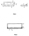
- FIG. 3 shows a further example (not the subject of the invention), again showing on the one hand a perspective view and on the other hand an enlarged cross-sectional view of an edge region of this embodiment.
- a conventional glass slide 2, on which a laser-light-absorbing membrane rests, is used as the carrier material.
- the laser light absorbing membrane 1 is held on the glass slide 2 by means of a particular circulating adhesive tape 3 having the shape of a mask corresponding to the glass slide, i. the adhesive tape 3 is in the form of a rectangular rim, wherein the inner edge region rests on the lateral surface of the membrane 1, while the outer edge region of the adhesive tape 3 rests on the outer surface of the glass slide, so that the laser-light absorbing membrane and the glass Slide 2 are held together firmly and in turn an extremely compact unit, which is correspondingly easy to handle, is provided.
- FIG. 4 shows a further exemplary embodiment of a carrier device according to the invention.
- the support device is basically constructed similar to the carrier device shown in Figure 2 and shown in the form of a cross-sectional view.
- the carrier device thus comprises a frame 3 which holds together and clamps the laser-light-absorbing membrane 1 and the laser-light-permeable membrane 2 located underneath and serving as a support for the laser-light-absorbing membrane.
- the frame 3 is designed to be as thin as possible in order to enable closer approach of the objective of the particular microscope used to the preparation located on the laser-light-absorbing membrane 1.
- the collecting container used to collect out-catalyzed biological objects can be brought closer to the carrier device, so that the biological objects can be catapulted out with less scattering.
- a cuboid container 5 is placed with a filling connection (not shown) for living (liquid) cell cultures and glued to the frame 3, for example with the aid of a silicone adhesive 6.
- the interior of the container 5 is thus hermetically sealed, so that the cell cultures located in the container 5 and on the laser-light-absorbing membrane 1 can grow in an incubator on the carrier device.
- the container 5 can be torn off by exerting a corresponding tensile force from the frame 3, so that the carrier device remaining thereafter can be used analogously to the carrier device shown in FIG ,
- the accomplished by the silicone adhesive 6 attachment of the container 5 to the frame 3 is thus solvable.
- the container can also be attached in a detachable manner to the carrier device or, preferably, to the frame 3 of the carrier device, for example by means of a vacuum attachment.
- the container 5 does not necessarily have to have a circumference matched to the circumference of the surrounding frame 3, as in the embodiment shown in FIG.
- the height of the container 5 may be for example of the order of 1 cm.
- a support means 2 was used in each case as a support for the laser-light-absorbing membrane 1.
- the use of a laser-light-absorbing membrane (compare the exemplary embodiments illustrated in Figure 1, Figure 2 and Figure 4) as a carrier means 2 is compared with the use of a glass slide (see the example shown in Figure 3) in particular in strongly magnifying microscopes advantageous because a support membrane has better optical properties and thus improves the microscopy ability.
- the present invention is not limited to the use of a support means of the type described above, but it can be completely dispensed with a support means 2, in which case only the laser light absorbing Membrane is held and tensioned as described above, in order to achieve a sufficiently large firmness of the laser light absorbing membrane 1.
- a support means of the type described above
- the laser-light-absorbing membrane 1 may, for example, be glued to the frame 3, which is sufficient in particular when the preparation applied to the laser-light-absorbing membrane 1 is subsequently subjected to no further chemical procedures.
- the manner of holding the laser light absorbing membrane 1 in the frame 3 without using an adhesive is advantageous because of the improved chemical resistance when the preparation applied to the laser light absorbing membrane 1 is to be subjected to chemical procedures.
- a carrier 2 of the type described above, in particular a support membrane advantageous because otherwise using only the laser light absorbing membrane 1 as a carrier for the biological material thereon when cutting and catapulting individual biological objects fluid would flow through the resulting holes in the membrane 1.
Landscapes
- Immunology (AREA)
- Pathology (AREA)
- Life Sciences & Earth Sciences (AREA)
- Chemical & Material Sciences (AREA)
- Analytical Chemistry (AREA)
- Biochemistry (AREA)
- General Health & Medical Sciences (AREA)
- General Physics & Mathematics (AREA)
- Health & Medical Sciences (AREA)
- Physics & Mathematics (AREA)
- Sampling And Sample Adjustment (AREA)
- Apparatus Associated With Microorganisms And Enzymes (AREA)
- Investigating Or Analysing Biological Materials (AREA)
- Control And Other Processes For Unpacking Of Materials (AREA)
- Removal Of Insulation Or Armoring From Wires Or Cables (AREA)
- Separation Using Semi-Permeable Membranes (AREA)
- External Artificial Organs (AREA)
Claims (21)
- Dispositif support pour une préparation, en particulier pour une préparation biologique, permettant la séparation par rayon laser d'objets individuels contenus dans la préparation, comprenant une membrane absorbant la lumière laser (1) destinée à recevoir la préparation, un moyen de support (2) prévu pour porter la membrane absorbant la lumière laser (1) et des moyens de maintien (3, 4) qui sont réalisés de telle manière qu'ils maintiennent ensemble la membrane absorbant la lumière laser (1) et le moyen de support (2) et tendent la membrane absorbant la lumière laser (1), caractérisé en ce que le moyen de support (2) est une autre membrane sur laquelle la membrane absorbant la lumière laser (1) est disposée directement.
- Dispositif support selon la revendication 1, caractérisé en ce que la membrane absorbant la lumière laser (1) est une membrane en polyéthylène naphtalène.
- Dispositif support selon la revendication 2, caractérisé en ce que la membrane en polyéthylène naphtalène possède une épaisseur d'environ 1,35 µm.
- Dispositif support selon la revendication 1, caractérisé en ce que la membrane absorbant la lumière laser (1) est une membrane en polyester.
- Dispositif support selon la revendication 4, caractérisé en ce que la membrane en polyester possède une épaisseur de 0,9 µm à 1 µm.
- Dispositif support selon l'une quelconque des revendications précédentes, caractérisé en ce que l'autre membrane (2) est réalisée en téflon.
- Dispositif support selon l'une quelconque des revendications précédentes, caractérisé en ce que l'autre membrane (2) possède une épaisseur d'environ 20 µm.
- Dispositif support selon l'une quelconque des revendications précédentes, caractérisé en ce que l'autre membrane (2) est transparente à la lumière laser.
- Dispositif support selon l'une quelconque des revendications précédentes, caractérisé en ce que la membrane absorbant la lumière laser (1) est hydrophilisée.
- Dispositif support selon l'une quelconque des revendications précédentes, caractérisé en ce que les moyens de maintien (3, 4) sont réalisés de telle manière qu'ils entourent la membrane absorbant la lumière laser (1) et l'autre membrane (2).
- Dispositif support selon l'une quelconque des revendications précédentes, caractérisé en ce que les moyens de maintien (3, 4) sont réalisés sous la forme d'un cadre qui tend la membrane absorbant la lumière laser (1) et l'autre membrane (2).
- Dispositif support selon la revendication 11, caractérisé en ce que la membrane absorbant la lumière laser (1) est fixée sur le cadre.
- Dispositif support selon la revendication 12, caractérisé en ce que la membrane absorbant la lumière laser (1) est collée sur le cadre.
- Dispositif support selon l'une quelconque des revendications précédentes, caractérisé en ce que les moyens de maintien (3, 4) font partie intégrante d'une boîte de Pétri.
- Dispositif support selon la revendication 14, caractérisé en ce que la membrane absorbant la lumière laser (1) et l'autre membrane (2) sont maintenues au fond de la boîte de Pétri par les moyens de maintien (3, 4).
- Dispositif support selon l'une des revendications 1 à 9, caractérisé en ce que les moyens de fixation (3) sont réalisés sous la forme d'un ruban adhésif, la surface adhésive du ruban adhésif (3) reposant sur la surface de bordure de la membrane absorbant la lumière laser (1), d'une part, et sur l'autre membrane (2), d'autre part.
- Dispositif support selon l'une quelconque des revendications précédentes, caractérisé en ce qu'il est prévu un récipient (5) qui est destiné à recevoir la préparation et est fixé de manière séparable sur le dispositif support à l'aide de moyens de fixation (6).
- Dispositif support selon la revendication 17, caractérisé en ce que les moyens de fixation (6) sont réalisés de telle manière que, par eux, il existe un assemblage adhésif séparable entre le récipient (5) et le dispositif support.
- Dispositif support selon la revendication 17 ou 18, caractérisé en ce que les moyens de fixation (6) sont réalisés de telle manière que la fixation obtenue par eux du récipient (5) sur le dispositif support est séparable en exerçant une force appliquée sur le récipient (5) ou le dispositif support.
- Dispositif support selon l'une des revendications 17 à 19, caractérisé en ce que le récipient (5) est fixé à l'aide des moyens de fixation (6) sur les moyens de maintien (3, 4) du dispositif support.
- Dispositif support selon l'une des revendications 17 à 20, caractérisé en ce que le récipient (5) est réalisé de telle manière que, dans le cas de l'utilisation de cultures de cellules vivantes comme préparation, celles-ci peuvent se développer sur le dispositif support à l'intérieur du récipient (5).
Applications Claiming Priority (3)
| Application Number | Priority Date | Filing Date | Title |
|---|---|---|---|
| DE10039979 | 2000-08-16 | ||
| DE10039979A DE10039979A1 (de) | 2000-08-16 | 2000-08-16 | Trägervorrichtung für ein Präparat zum Separieren einzelner Objekte aus dem Präparat mittels Laserstrahlung |
| PCT/EP2001/009468 WO2002014833A1 (fr) | 2000-08-16 | 2001-08-16 | Dispositif support pour une preparation permettant la separation par irradiation laser d'objets individuels contenus dans ladite preparation |
Publications (2)
| Publication Number | Publication Date |
|---|---|
| EP1309846A1 EP1309846A1 (fr) | 2003-05-14 |
| EP1309846B1 true EP1309846B1 (fr) | 2006-03-22 |
Family
ID=7652586
Family Applications (1)
| Application Number | Title | Priority Date | Filing Date |
|---|---|---|---|
| EP01974196A Expired - Lifetime EP1309846B1 (fr) | 2000-08-16 | 2001-08-16 | Dispositif support pour une preparation permettant la separation par irradiation laser d'objets individuels contenus dans ladite preparation |
Country Status (7)
| Country | Link |
|---|---|
| US (1) | US7318999B2 (fr) |
| EP (1) | EP1309846B1 (fr) |
| JP (1) | JP3626952B2 (fr) |
| AT (1) | ATE321263T1 (fr) |
| AU (1) | AU2001293777A1 (fr) |
| DE (2) | DE10039979A1 (fr) |
| WO (1) | WO2002014833A1 (fr) |
Cited By (1)
| Publication number | Priority date | Publication date | Assignee | Title |
|---|---|---|---|---|
| WO2009146680A1 (fr) | 2008-06-04 | 2009-12-10 | Universität Zu Lübeck | Système de support pour la microdissection au laser et le transport induit par laser de matériau biologique et de cellules vivantes |
Families Citing this family (14)
| Publication number | Priority date | Publication date | Assignee | Title |
|---|---|---|---|---|
| JP3773831B2 (ja) * | 2000-10-31 | 2006-05-10 | 富士写真フイルム株式会社 | 生体試料の切断方法およびそれに用いる装置 |
| DE10102034A1 (de) * | 2001-01-18 | 2002-08-08 | Leica Microsystems | Objektträger, Mikrodissektionseinrichtung mit Objektträger und Verfahren zur Mikrodissektion |
| DE10135091A1 (de) * | 2001-07-15 | 2003-01-30 | Universitaetsklinikum Charite | Verfahren, Einrichtung und Objektträger zur Mikrodissektion |
| ATE474444T1 (de) * | 2002-05-24 | 2010-07-15 | Koninkl Philips Electronics Nv | Verfahren zur übertragung von einem an einen träger befestigten bauelement in eine gewünschte lage auf einen träger und einrichtung dafur |
| CA2488391A1 (fr) * | 2002-07-26 | 2004-02-19 | P.A.L.M. Microlaser Technologies Ag | Procede de preparation d'une matiere biologique pour une analyse au microscope et systeme correspondant comprenant une matiere biologique preparee par ce procede |
| DE10234755A1 (de) * | 2002-07-30 | 2004-02-26 | Leica Microsystems Wetzlar Gmbh | Trägervorrichtung für ein biologisches, mittels Laser-Mikrodissektion schneidbares Präparat |
| DE10329674B4 (de) * | 2003-06-30 | 2014-08-14 | Karsten König | Laserverfahren und Anordnung zur Markierung und Gewinnung von Materialien, Zellbestandteilen, Zellen und Gewebebestandteilen |
| DE10346458A1 (de) * | 2003-10-02 | 2005-05-12 | Leica Microsystems | Verfahren zur Laser-Mikrodissektion |
| DE10358566B4 (de) * | 2003-12-15 | 2012-03-01 | P.A.L.M. Microlaser Technologies Ag | Haltevorrichtung zum Halten eines Aufnahmemittels für ein biologisches Objekt sowie entsprechendes Verfahren zur Laser-Mikrodissektion |
| DE10358565B4 (de) * | 2003-12-15 | 2007-06-28 | P.A.L.M. Microlaser Technologies Ag | Aufnahmeelement zum Aufnehmen eines aus einer biologischen Masse mittels Laserstrahlung herausgelösten Objekts und Verfahren zur Gewinnung und Verarbeitung eines biologischen Objekts |
| DE102005061561A1 (de) | 2005-12-22 | 2007-06-28 | P.A.L.M. Microlaser Technologies Ag | Laser-Mikrodissektionsverfahren, Steuersystem für eine Laser-Mikrodissektionsvorrichtung und Trägervorrichtung |
| US7807108B2 (en) * | 2006-09-18 | 2010-10-05 | Leica Microsystems Cms Gmbh | Apparatus for receiving biological specimens |
| DE202008014487U1 (de) | 2008-10-31 | 2009-01-22 | Mmi Ag | Petrischale für Zellkultivierung und Mikroskopie |
| CN104619856A (zh) * | 2012-05-29 | 2015-05-13 | 加利福尼亚大学董事会 | 用于从流体样品中分离细胞的系统、方法及部件 |
Family Cites Families (15)
| Publication number | Priority date | Publication date | Assignee | Title |
|---|---|---|---|---|
| US4046457A (en) * | 1973-12-26 | 1977-09-06 | Polaroid Corporation | Polymeric film base carrying fluoropolymer anti-reflection coating |
| US5589333A (en) * | 1992-02-03 | 1996-12-31 | Thomas Jefferson University | In situ polymerase chain reaction |
| US5294695A (en) * | 1993-03-15 | 1994-03-15 | Skc Limited | Process for preparing polyethylene naphthalate |
| US5518925A (en) * | 1995-06-06 | 1996-05-21 | Becton Dickinson Co | Culture slide assembly |
| WO1997029354A1 (fr) * | 1996-02-05 | 1997-08-14 | Bayer Aktiengesellschaft | Procede et dispositif pour trier et recuperer des objets biologiques deposes sur un support plat, tels que des cellules biologiques ou des organites cellulaires, des coupes histologiques, des particules de chromosomes etc., au moyen de faisceaux laser |
| JP3635777B2 (ja) * | 1996-03-20 | 2005-04-06 | 株式会社堀場製作所 | 試料セル |
| US5859699A (en) * | 1997-02-07 | 1999-01-12 | Arcturus Engineering, Inc. | Laser capture microdissection analysis vessel |
| US6495195B2 (en) * | 1997-02-14 | 2002-12-17 | Arcturus Engineering, Inc. | Broadband absorbing film for laser capture microdissection |
| EP0926480B9 (fr) * | 1997-10-18 | 2004-07-28 | Malte Dr. Böhm | Dispositif de manipulation d'échantillons pour la micro-dissection assistée par membrane |
| DE29823783U1 (de) * | 1997-10-18 | 2000-06-08 | Böhm, Malte, Dr.med., 39104 Magdeburg | Vorrichtung zur Handhabung von Proben für die membrangestützte Mikrodissektion |
| DE19818425A1 (de) * | 1997-10-18 | 1999-07-15 | Malte Dr Med Boehm | Vorrichtung zur Handhabung von Proben für die membrangestützte Mikrodissektion |
| JPH11148887A (ja) * | 1997-11-17 | 1999-06-02 | Japan Science & Technology Corp | 生体サンプルの切断方法および切断片回収方法、 並びにそのための装置 |
| EP0993964A3 (fr) | 1998-10-16 | 2000-11-22 | Markem Corporation | Couches pour marquage par laser |
| DE69941724D1 (de) * | 1998-12-10 | 2010-01-07 | Us Gov Health & Human Serv | Laseranheftungs-mikrodissektion mit zwei laserpulsen zum ausdehnen und zurückziehen einer schicht |
| DE10003588C2 (de) * | 2000-01-25 | 2002-10-02 | Sl Microtest Wissenschaftliche | Verfahren zum Isolieren eines Teils einer Schicht biologischen Materials |
-
2000
- 2000-08-16 DE DE10039979A patent/DE10039979A1/de not_active Ceased
-
2001
- 2001-08-16 JP JP2002519913A patent/JP3626952B2/ja not_active Expired - Lifetime
- 2001-08-16 US US10/344,507 patent/US7318999B2/en not_active Expired - Lifetime
- 2001-08-16 WO PCT/EP2001/009468 patent/WO2002014833A1/fr not_active Ceased
- 2001-08-16 DE DE50109312T patent/DE50109312D1/de not_active Expired - Lifetime
- 2001-08-16 EP EP01974196A patent/EP1309846B1/fr not_active Expired - Lifetime
- 2001-08-16 AU AU2001293777A patent/AU2001293777A1/en not_active Abandoned
- 2001-08-16 AT AT01974196T patent/ATE321263T1/de not_active IP Right Cessation
Cited By (1)
| Publication number | Priority date | Publication date | Assignee | Title |
|---|---|---|---|---|
| WO2009146680A1 (fr) | 2008-06-04 | 2009-12-10 | Universität Zu Lübeck | Système de support pour la microdissection au laser et le transport induit par laser de matériau biologique et de cellules vivantes |
Also Published As
| Publication number | Publication date |
|---|---|
| DE50109312D1 (de) | 2006-05-11 |
| ATE321263T1 (de) | 2006-04-15 |
| JP2004506892A (ja) | 2004-03-04 |
| US20030180941A1 (en) | 2003-09-25 |
| DE10039979A1 (de) | 2002-03-07 |
| JP3626952B2 (ja) | 2005-03-09 |
| AU2001293777A1 (en) | 2002-02-25 |
| EP1309846A1 (fr) | 2003-05-14 |
| US7318999B2 (en) | 2008-01-15 |
| WO2002014833A1 (fr) | 2002-02-21 |
Similar Documents
| Publication | Publication Date | Title |
|---|---|---|
| EP1309846B1 (fr) | Dispositif support pour une preparation permettant la separation par irradiation laser d'objets individuels contenus dans ladite preparation | |
| EP0879408B1 (fr) | Procede de micro-injection sans contact, de tri et de production d'objets biologiques obtenus de maniere planaire, a l'aide de faisceaux laser | |
| EP1250583B1 (fr) | Procede pour isoler une partie d'une couche d'un materiau biologique | |
| EP3017296B1 (fr) | Système de microdissection laser et procédé d'analyse d'échantillons contenant de l'acide nucléique | |
| DE19616216A1 (de) | Verfahren und Vorrichtung zur Gewinnung von laserdissektierten Partikeln wie biologische Zellen bzw. Zellorganellen, Chromosomenteilchen etc. | |
| EP1537401A1 (fr) | Dispositif support destine a une preparation biologique pouvant etre decoupee par microdissection laser | |
| DE19603996A1 (de) | Sortierverfahren für planar ausgebrachte biologische Objekte mit Laserstrahlen | |
| EP3039399A1 (fr) | Système de microdissection par laser et procédé pour système de microdissection par laser | |
| WO2010078891A1 (fr) | Unité de transfert et procédé pour prendre un support d'un dispositif de traitement | |
| EP1963815B1 (fr) | Procédé de microdissection au laser, système de commande d'un dispositif de microdissection au laser et dispositif de support | |
| DE10358566B4 (de) | Haltevorrichtung zum Halten eines Aufnahmemittels für ein biologisches Objekt sowie entsprechendes Verfahren zur Laser-Mikrodissektion | |
| DE10135091A1 (de) | Verfahren, Einrichtung und Objektträger zur Mikrodissektion | |
| EP2011630A1 (fr) | Procédé destiné à la réalisation d'un élément d'analyse | |
| DE20214835U1 (de) | Trägervorrichtung für ein biologisches, mittels Laser-Mikrodissektion schneidbares Präparat | |
| DE10329674B4 (de) | Laserverfahren und Anordnung zur Markierung und Gewinnung von Materialien, Zellbestandteilen, Zellen und Gewebebestandteilen | |
| WO2002057746A2 (fr) | Porte-objets, dispositif de microdissection muni d'un porte-objets et procede de microdissection | |
| DE19818425A1 (de) | Vorrichtung zur Handhabung von Proben für die membrangestützte Mikrodissektion | |
| DE102019102852B3 (de) | Verfahren zur Lasermikrodissektion, Lasermikrodissektionssystem und Computerprogramm | |
| DE10358565B4 (de) | Aufnahmeelement zum Aufnehmen eines aus einer biologischen Masse mittels Laserstrahlung herausgelösten Objekts und Verfahren zur Gewinnung und Verarbeitung eines biologischen Objekts | |
| EP2283337B1 (fr) | Système de support pour la microdissection au laser et le transport induit par laser de matériau biologique et de cellules vivantes | |
| DE102016110750A1 (de) | Trägermembran für die Lasermikrodissektion einer auf die Trägermembran aufgebrachten Probe, Lasermikrodissektionseinrichtung und Lasermikrodissektionsverfahren unter Verwendung einer solchen Trägermembran | |
| EP0926480A2 (fr) | Dispositif de manipulation d'échantillons pour la micro-dissection assistée par membrane | |
| EP0327144A2 (fr) | Récipient pour recevoir un échantillon pâteux et procédé de traitement d'échantillons pâteux | |
| DE29823783U1 (de) | Vorrichtung zur Handhabung von Proben für die membrangestützte Mikrodissektion | |
| DE102020212266A1 (de) | Mit vliesstoff verschlossener behälter |
Legal Events
| Date | Code | Title | Description |
|---|---|---|---|
| PUAI | Public reference made under article 153(3) epc to a published international application that has entered the european phase |
Free format text: ORIGINAL CODE: 0009012 |
|
| 17P | Request for examination filed |
Effective date: 20030212 |
|
| AK | Designated contracting states |
Designated state(s): AT BE CH CY DE DK ES FI FR GB GR IE IT LI LU MC NL PT SE TR |
|
| AX | Request for extension of the european patent |
Extension state: AL LT LV MK RO SI |
|
| GRAP | Despatch of communication of intention to grant a patent |
Free format text: ORIGINAL CODE: EPIDOSNIGR1 |
|
| GRAS | Grant fee paid |
Free format text: ORIGINAL CODE: EPIDOSNIGR3 |
|
| GRAA | (expected) grant |
Free format text: ORIGINAL CODE: 0009210 |
|
| AK | Designated contracting states |
Kind code of ref document: B1 Designated state(s): AT BE CH CY DE DK ES FI FR GB GR IE IT LI LU MC NL PT SE TR |
|
| PG25 | Lapsed in a contracting state [announced via postgrant information from national office to epo] |
Ref country code: IT Free format text: LAPSE BECAUSE OF FAILURE TO SUBMIT A TRANSLATION OF THE DESCRIPTION OR TO PAY THE FEE WITHIN THE PRESCRIBED TIME-LIMIT;WARNING: LAPSES OF ITALIAN PATENTS WITH EFFECTIVE DATE BEFORE 2007 MAY HAVE OCCURRED AT ANY TIME BEFORE 2007. THE CORRECT EFFECTIVE DATE MAY BE DIFFERENT FROM THE ONE RECORDED. Effective date: 20060322 Ref country code: IE Free format text: LAPSE BECAUSE OF FAILURE TO SUBMIT A TRANSLATION OF THE DESCRIPTION OR TO PAY THE FEE WITHIN THE PRESCRIBED TIME-LIMIT Effective date: 20060322 Ref country code: NL Free format text: LAPSE BECAUSE OF FAILURE TO SUBMIT A TRANSLATION OF THE DESCRIPTION OR TO PAY THE FEE WITHIN THE PRESCRIBED TIME-LIMIT Effective date: 20060322 |
|
| REG | Reference to a national code |
Ref country code: GB Ref legal event code: FG4D Free format text: NOT ENGLISH |
|
| REG | Reference to a national code |
Ref country code: CH Ref legal event code: NV Representative=s name: SERVOPATENT GMBH Ref country code: CH Ref legal event code: EP |
|
| GBT | Gb: translation of ep patent filed (gb section 77(6)(a)/1977) |
Effective date: 20060322 |
|
| REG | Reference to a national code |
Ref country code: IE Ref legal event code: FG4D Free format text: LANGUAGE OF EP DOCUMENT: GERMAN |
|
| REF | Corresponds to: |
Ref document number: 50109312 Country of ref document: DE Date of ref document: 20060511 Kind code of ref document: P |
|
| PG25 | Lapsed in a contracting state [announced via postgrant information from national office to epo] |
Ref country code: SE Free format text: LAPSE BECAUSE OF FAILURE TO SUBMIT A TRANSLATION OF THE DESCRIPTION OR TO PAY THE FEE WITHIN THE PRESCRIBED TIME-LIMIT Effective date: 20060622 Ref country code: DK Free format text: LAPSE BECAUSE OF FAILURE TO SUBMIT A TRANSLATION OF THE DESCRIPTION OR TO PAY THE FEE WITHIN THE PRESCRIBED TIME-LIMIT Effective date: 20060622 |
|
| PG25 | Lapsed in a contracting state [announced via postgrant information from national office to epo] |
Ref country code: ES Free format text: LAPSE BECAUSE OF FAILURE TO SUBMIT A TRANSLATION OF THE DESCRIPTION OR TO PAY THE FEE WITHIN THE PRESCRIBED TIME-LIMIT Effective date: 20060703 |
|
| PG25 | Lapsed in a contracting state [announced via postgrant information from national office to epo] |
Ref country code: PT Free format text: LAPSE BECAUSE OF FAILURE TO SUBMIT A TRANSLATION OF THE DESCRIPTION OR TO PAY THE FEE WITHIN THE PRESCRIBED TIME-LIMIT Effective date: 20060822 |
|
| PG25 | Lapsed in a contracting state [announced via postgrant information from national office to epo] |
Ref country code: BE Free format text: LAPSE BECAUSE OF NON-PAYMENT OF DUE FEES Effective date: 20060831 Ref country code: MC Free format text: LAPSE BECAUSE OF NON-PAYMENT OF DUE FEES Effective date: 20060831 |
|
| NLV1 | Nl: lapsed or annulled due to failure to fulfill the requirements of art. 29p and 29m of the patents act | ||
| REG | Reference to a national code |
Ref country code: IE Ref legal event code: FD4D |
|
| ET | Fr: translation filed | ||
| PLBE | No opposition filed within time limit |
Free format text: ORIGINAL CODE: 0009261 |
|
| STAA | Information on the status of an ep patent application or granted ep patent |
Free format text: STATUS: NO OPPOSITION FILED WITHIN TIME LIMIT |
|
| 26N | No opposition filed |
Effective date: 20061227 |
|
| GBPC | Gb: european patent ceased through non-payment of renewal fee |
Effective date: 20060816 |
|
| REG | Reference to a national code |
Ref country code: FR Ref legal event code: ST Effective date: 20070430 |
|
| PG25 | Lapsed in a contracting state [announced via postgrant information from national office to epo] |
Ref country code: AT Free format text: LAPSE BECAUSE OF NON-PAYMENT OF DUE FEES Effective date: 20060816 Ref country code: GB Free format text: LAPSE BECAUSE OF NON-PAYMENT OF DUE FEES Effective date: 20060816 |
|
| BERE | Be: lapsed |
Owner name: P.A.L.M. MICROLASER TECHNOLOGIES A.G. Effective date: 20060831 |
|
| REG | Reference to a national code |
Ref country code: CH Ref legal event code: PFA Owner name: P.A.L.M. MICROLASER TECHNOLOGIES AG Free format text: P.A.L.M. MICROLASER TECHNOLOGIES AG#AM NEULAND 12#82347 BERNRIED (DE) -TRANSFER TO- P.A.L.M. MICROLASER TECHNOLOGIES AG#AM NEULAND 12#82347 BERNRIED (DE) |
|
| PG25 | Lapsed in a contracting state [announced via postgrant information from national office to epo] |
Ref country code: GR Free format text: LAPSE BECAUSE OF FAILURE TO SUBMIT A TRANSLATION OF THE DESCRIPTION OR TO PAY THE FEE WITHIN THE PRESCRIBED TIME-LIMIT Effective date: 20060623 Ref country code: FR Free format text: LAPSE BECAUSE OF NON-PAYMENT OF DUE FEES Effective date: 20060831 |
|
| PG25 | Lapsed in a contracting state [announced via postgrant information from national office to epo] |
Ref country code: FI Free format text: LAPSE BECAUSE OF FAILURE TO SUBMIT A TRANSLATION OF THE DESCRIPTION OR TO PAY THE FEE WITHIN THE PRESCRIBED TIME-LIMIT Effective date: 20060322 |
|
| PG25 | Lapsed in a contracting state [announced via postgrant information from national office to epo] |
Ref country code: LU Free format text: LAPSE BECAUSE OF NON-PAYMENT OF DUE FEES Effective date: 20060816 Ref country code: TR Free format text: LAPSE BECAUSE OF FAILURE TO SUBMIT A TRANSLATION OF THE DESCRIPTION OR TO PAY THE FEE WITHIN THE PRESCRIBED TIME-LIMIT Effective date: 20060322 |
|
| PG25 | Lapsed in a contracting state [announced via postgrant information from national office to epo] |
Ref country code: CY Free format text: LAPSE BECAUSE OF FAILURE TO SUBMIT A TRANSLATION OF THE DESCRIPTION OR TO PAY THE FEE WITHIN THE PRESCRIBED TIME-LIMIT Effective date: 20060322 |
|
| REG | Reference to a national code |
Ref country code: DE Ref legal event code: R082 Ref document number: 50109312 Country of ref document: DE Representative=s name: PATENT- UND RECHTSANWAELTE KRAUS & WEISERT, DE |
|
| REG | Reference to a national code |
Ref country code: DE Ref legal event code: R081 Ref document number: 50109312 Country of ref document: DE Owner name: CARL ZEISS MICROSCOPY GMBH, DE Free format text: FORMER OWNER: P.A.L.M. MICROLASER TECHNOLOGIES AG, 82347 BERNRIED, DE Effective date: 20130118 Ref country code: DE Ref legal event code: R082 Ref document number: 50109312 Country of ref document: DE Representative=s name: PATENT- UND RECHTSANWAELTE KRAUS & WEISERT, DE Effective date: 20130118 Ref country code: DE Ref legal event code: R082 Ref document number: 50109312 Country of ref document: DE Representative=s name: KRAUS & WEISERT PATENTANWAELTE PARTGMBB, DE Effective date: 20130118 |
|
| REG | Reference to a national code |
Ref country code: CH Ref legal event code: PCAR Free format text: NEW ADDRESS: WANNERSTRASSE 9/1, 8045 ZUERICH (CH) |
|
| PGFP | Annual fee paid to national office [announced via postgrant information from national office to epo] |
Ref country code: DE Payment date: 20200819 Year of fee payment: 20 |
|
| PGFP | Annual fee paid to national office [announced via postgrant information from national office to epo] |
Ref country code: CH Payment date: 20200819 Year of fee payment: 20 |
|
| REG | Reference to a national code |
Ref country code: DE Ref legal event code: R071 Ref document number: 50109312 Country of ref document: DE |
|
| REG | Reference to a national code |
Ref country code: CH Ref legal event code: PL |