EP1310601A2 - Fundamentplatte - Google Patents
Fundamentplatte Download PDFInfo
- Publication number
- EP1310601A2 EP1310601A2 EP02257816A EP02257816A EP1310601A2 EP 1310601 A2 EP1310601 A2 EP 1310601A2 EP 02257816 A EP02257816 A EP 02257816A EP 02257816 A EP02257816 A EP 02257816A EP 1310601 A2 EP1310601 A2 EP 1310601A2
- Authority
- EP
- European Patent Office
- Prior art keywords
- concrete
- support
- formwork
- raft
- further including
- Prior art date
- Legal status (The legal status is an assumption and is not a legal conclusion. Google has not performed a legal analysis and makes no representation as to the accuracy of the status listed.)
- Withdrawn
Links
- 239000004567 concrete Substances 0.000 claims abstract description 50
- 238000000034 method Methods 0.000 claims abstract description 31
- 238000009415 formwork Methods 0.000 claims abstract description 30
- 239000002184 metal Substances 0.000 claims abstract description 8
- 229910001220 stainless steel Inorganic materials 0.000 claims abstract description 6
- 239000010935 stainless steel Substances 0.000 claims abstract description 6
- 238000009416 shuttering Methods 0.000 claims abstract description 4
- 239000011800 void material Substances 0.000 claims description 29
- 239000011449 brick Substances 0.000 claims description 9
- 239000000463 material Substances 0.000 claims description 7
- 238000013022 venting Methods 0.000 claims description 6
- 239000002689 soil Substances 0.000 claims description 2
- 230000002787 reinforcement Effects 0.000 description 9
- 125000006850 spacer group Chemical group 0.000 description 8
- 230000008878 coupling Effects 0.000 description 4
- 238000010168 coupling process Methods 0.000 description 4
- 238000005859 coupling reaction Methods 0.000 description 4
- 238000010276 construction Methods 0.000 description 3
- 238000011068 loading method Methods 0.000 description 3
- 229910000831 Steel Inorganic materials 0.000 description 2
- 239000007788 liquid Substances 0.000 description 2
- 239000010959 steel Substances 0.000 description 2
- XLYOFNOQVPJJNP-UHFFFAOYSA-N water Substances O XLYOFNOQVPJJNP-UHFFFAOYSA-N 0.000 description 2
- 239000004793 Polystyrene Substances 0.000 description 1
- 241000283984 Rodentia Species 0.000 description 1
- 230000003466 anti-cipated effect Effects 0.000 description 1
- 230000004888 barrier function Effects 0.000 description 1
- 230000005540 biological transmission Effects 0.000 description 1
- 239000012528 membrane Substances 0.000 description 1
- 229920002223 polystyrene Polymers 0.000 description 1
- 239000011150 reinforced concrete Substances 0.000 description 1
- 238000005728 strengthening Methods 0.000 description 1
Images





Classifications
-
- E—FIXED CONSTRUCTIONS
- E02—HYDRAULIC ENGINEERING; FOUNDATIONS; SOIL SHIFTING
- E02D—FOUNDATIONS; EXCAVATIONS; EMBANKMENTS; UNDERGROUND OR UNDERWATER STRUCTURES
- E02D27/00—Foundations as substructures
- E02D27/01—Flat foundations
- E02D27/02—Flat foundations without substantial excavation
Definitions
- This invention relates to a structure for use in, and a method for, constructing a concrete foundation raft or low level beam and, in particular, to foundation rafts or beams which are spaced from the ground.
- a collapsible or crushable spacer made for example of hardboard, cardboard, and/or polystyrene has been used as a temporary support. Once the foundation raft or beam has been constructed, these spacers either degrade or are designed to compress with any uplift of the ground. Generally these techniques are expensive. Collapsible material can collapse prematurely, particularly in wet weather, and compressible spacers require extra space to avoid the transmission of heave to the raft to the crushed material.
- GB-A-2329651 we suggested a method of constructing a concrete foundation raft or low level beam for a building or other superstructure comprising erecting formwork, which is held spaced above the ground by at least one interposed waterproof bag that is inflated with water or other liquid, pouring concrete in the formwork to form the raft or beam and, when the concrete has set, removing the water from the bag(s) to allow the bag(s) to collapse leaving a void between the underside of the raft or beam and the ground.
- EP-A-1116829 we described a method of constructing a concrete foundation raft or low level beam for a building or other superstructure, comprising the steps of erecting formwork, which is supported by a number of piles and by a frame to which the formwork is connected; and pouring concrete in the formwork to form the raft or beam, wherein at least part of the frame is incorporated within the concrete to provide reinforcement of the concrete.
- the frame is preferably constructed of a metal, such as steel, so that the concrete is substantially reinforced.
- the frame may be supported on the piles and, preferably, the formwork comprises a deck which is tied to the frame to prevent downward movement at the midpoints of the deck between the piles.
- the outer edges of the deck may be cut to the exact shape of the property and to accommodate one or more downstand units.
- the reinforcement is fixed and the one or more downstand units can be positioned at the edge of the decking and may then be secured to the reinforcement and/or the frame.
- the one or more downstand units provide support for edge shutters which are attached to the formwork. Once the edge shutters are in place, the concrete can then be poured.
- the frame ensures that any void between the formwork and the ground can be kept completely clear during construction while ensuring that the formwork is securely supported. As there is no direct support between the ground and the formwork, this method can be used when the ground is uneven.
- the provision of downstand units ensures that the sides of the formwork are supported and provide convenient attachment for the edge shutters. Additionally, the frame provides reinforcement to the concrete and means that additional reinforcement may not be needed. Of course, further reinforcement may be added if required.
- the second earlier application also claimed a frame for use in constructing a concrete foundation raft or low level beam for a building or other superstructure, comprising at least one pair of elongate tubes, comprising a first and a second tube, which are arranged to be connected, in use, to a deck; a third elongate tube, substantially parallel to the first and second tubes and which is spaced from the plane in which the other two tubes lie to form, in section, a triangular arrangement; and connecting means for joining the first and second tubes to the third tube.
- a third aspect of that invention included a method of constructing a concrete foundation raft or low level beam for a building or other superstructure, comprising the steps of: erecting formwork, which is supported by a number of piles, by at least one interposed bag that is inflated with air and by one or more downstand units; pouring concrete in the formwork to form the raft or beam; and removing the air from the bag(s) when the concrete has set to allow the bag(s) to collapse, leaving a void between the underside of the raft or beam and the ground.
- the bags can be filled and emptied more quickly and easily.
- the bag(s) can be used together with one or more usually, a pair of formers which are preferably formed from timber. These formers permitted the size of the void to be increased without the need for many differently sized bags.
- a method of constructing a concrete foundation raft or low level beam for a building or other superstructure comprising the steps of:
- the invention addresses three issues in one.
- the angle support acts as a temporary shutter to a slab while the concrete is poured and cured.
- the angle, which runs around the periphery of the slab preferably includes stainless ties which extend back into the concrete slab in order to provide a permanent key so as to ensure that the angle is permanently "held” by the cured concrete.
- the angle provides permanent support to the outer brickwork skin of the building.
- the brickwork skin would typically support a single two or three storey building and may or may not include a widened detail at the bottom to support an additional course of bricks (to a metre high - commonly known as a plinth).
- slots are cut into the angle and a small passage is formed in the concrete and a corresponding hole cut into the timber decking to allow air to flow from the void below up through the cut of the timber decking, through the passage formed in the concrete, through the slot into the void behind the brickwork and subsequently into the atmosphere via the air bricks.
- the number of ties, their thickness and their configuration will depend on the anticipated brickwork loading.
- the angle itself would normally be between 4 and 8 mm but typically 5 or 6 mm.
- Increased strength for increased brickwork loadings is provided by small gusset plates welded in the corner of the angle. These features may be easily accommodated by the bricklayer who would chop out sections of brick as would be appropriate.
- Expanded metal may be provided on top of the angle, this is in turn bent down and "nailed" to the building and provides a barrier to prevent the ingress of soil and also rodents into the void.
- One variation on this proposal is that of forming an alternative means of venting the void, which alleviates the need for the slots.
- the angle sections typically 1.5 metres long are simply positioned leaving a small gap between them typically 50 to 100 mm.
- a sheet of thin material, typically metal can be secured to either the front or the back face to provide temporary support for the concrete. Once the concrete is secured the timber decking is cut out and airflow automatically rises directly from the void into the cavity brickwork.
- a venting element typically a telescopic vent, is inserted between adjacent angle sections and may or may not be inserted at least partially into a recess in the concrete slab. This enables air flow to easily pass into and out of the void beneath the concrete.
- the drawings include:
- a foundation raft 1 comprises a deck 2 and a frame 3, both of which are supported by a number of piles 4.
- the piles 4 have been preformed in the ground 5 and the uppermost section of the piles is of a greater diameter to the remainder of the pile.
- the piles 4 support the foundation raft 1 away from the ground, thus creating a void 7 which can accommodate potential ground heave.
- a number of spacers 8 are provided between the frame 3 and the deck 2.
- the frame and deck are connected together through the spacers 8.
- the spacers are usually formed from concrete and are provided to ensure that, as the concrete 9 is poured, it can flow around the underside of the frame and fully surround the lower part of the frame. Concrete 9 is poured onto the deck 2 and surrounds the frame and any additional reinforcement 10 which may be required.
- First 11 and second 12 members are horizontally spaced and substantially parallel to each other. They lie on the upper surface of a series of spacers 8.
- a third elongate member 13 is spaced from the first and second members to form, in section, a triangular arrangement.
- the first 11 and second 12 members are connected to the third member 13 by members 14 to create the framework 3.
- This framework 3 is then connected to the spacers 8 and the deck 2 by means of ties 15. This tying connection can be clearly seen in Fig. 3.
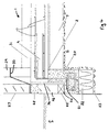
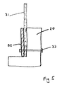
- Figures 4 and 5 show the arrangement at the one edge of the formwork 1 and show the provision of downstand units 20.
- the downstand unit 20 may be formed from concrete and it is connected to the reinforcement 10 via a steel connecting arm 21.
- the downstand unit 20 is connected to the reinforcement 10 prior to pouring the concrete 9.
- the downstand unit 20 is placed on a temporary support 22 during construction and this temporary support may be removed on completion of the construction.
- a wall 23 is provided to prevent the ground 5 migrating to the underside of the downstand units.
- the downstand unit 20 is provided with a step 24 which supports a series of pre-cast beams 25.
- the beams in turn support the outer skin of brickwork 26 and 27, including air bricks 28.
- the inner skin of brickwork 29 is supported directly on the raft itself and a damp proof membrane 30 is incorporated within the inner 29 and outer 27 courses of brickwork.
- Temporary shuttering 31 is provided and is secured to the downstand unit 20 by support detail 32. Bolts 33 can be removed to allow the removal of the shutter support 32 and then the main shutter 31 which spans adjacent units.
- the temporary shutters 31 are of sufficient height to form a raised boundary to the foundation raft to ensure that the concrete can be poured to the required depth. Once these edge shutters 31 are in place, the concrete 9 can then be poured.
- An air void 34 is provided between the outer skin of brickwork 26 and the downstand unit 20 or concrete 9. This is vented to the atmosphere through air bricks 28.
- Figure 6 shows an alternative foundation raft 50 consisting of a reinforced concrete slab 50 supporting building walls 51 and itself supported by piles 52.
- the piles are first put down and the slab is integrated with pile caps.
- a void 53 spaces the bottom of the slab 50 from the ground 54.
- Figure 7 indicates in vertical section how the void 53 might be created.
- decking 55 forming the bottom wall of formwork is spaced above a layer of blinding 56 on the ground 54 by an array of tubular bags 57, which may be laid out as seen in plan in Figure 9.
- each bag 57 has a closed end 58 and, at its opposite end, is connected to a hose 59 leading to a terminal 60, or a common terminal 60a in Figure 9, containing a non return valve and a tap.
- the hose may be a canvas hose similar to a fireman's hose.
- a pump could be connected to the block 60 to inflate the respective bag.
- the hose 59 could be used to pull the bag from the void after use.
- Figure 10 shows a bag 57 with a coupling device 61 having its wider, oval shaped end inserted in the end of the bag opposite the closed end 58.
- the size of the largest part of the coupling device can pass through a 225mm x 75mm hole.
- the coupling device has a narrow inlet/outlet tube 62 extending away from the bag. The tube can be connected to the hose.
- Figure 11 shows the provision of a pair of timber formers 61 comprising a main body 63 and a pair of longitudinally extending raised portions 62.
- the bag 57 sits between the pair of formers 61 and is in the fully inflated configuration.
- the formers increase that the shown size of the void 53 between the declining 55 and the blinding 56.
- each former has a different depth such that the size of the void can be varied between separate applications or to accommodate inconsistencies in the ground surface.
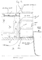
- the method shown involves the provision of a stainless steel angle 70 which acts as both a permanent shutter and support to the external brickwork 71.
- the angle typically 6 mm in thickness, is first placed upon the timber decking 72 and is secured with screws or nails to the timber decking.
- the angle is support via tie back straps 73 welded to the internal (as used) face of the angle at predetermined designed centres, the spacing and the length of the straps being determined by the loadings of the brickwork.
- the void 74 is vented by providing slots 75 in the vertical face of the angle and providing formers 76 which are cast into the concrete.
- the formers may either be a void in their own right or a soft void forming medium which is subsequently removed.
- the overall result is that air is allowed subsequently to flow from underneath the void decking, up into small recesses behind the angle face (vent/void), out through the slots, into a void behind the bricks and subsequently out through to the atmosphere by air bricks spaced at centres in accordance with building regulations.
- Strengthening gussets 77 may be provided at intervals along the angle as shown.
- a backing section of material (metal sheet) 77 is received between angles 70 spaced apart from one another.
- a slot 78 is cut in the timber decking 72. This configuration allows the air to flow from the void 74, via slot 78, behind the brickwork 71 and to atmosphere via the air brick.
- a venting element 80 inserted between adjacent angle supports 70 which are spaced apart as in Fig. 15, permits air flow from the void 74 to the atmosphere.
Landscapes
- Engineering & Computer Science (AREA)
- Mining & Mineral Resources (AREA)
- Life Sciences & Earth Sciences (AREA)
- General Life Sciences & Earth Sciences (AREA)
- Paleontology (AREA)
- Civil Engineering (AREA)
- General Engineering & Computer Science (AREA)
- Structural Engineering (AREA)
- Forms Removed On Construction Sites Or Auxiliary Members Thereof (AREA)
- Foundations (AREA)
Applications Claiming Priority (2)
| Application Number | Priority Date | Filing Date | Title |
|---|---|---|---|
| GB0127148 | 2001-11-12 | ||
| GB0127148A GB0127148D0 (en) | 2001-11-12 | 2001-11-12 | Improvements relating to foundation rafts |
Publications (2)
| Publication Number | Publication Date |
|---|---|
| EP1310601A2 true EP1310601A2 (de) | 2003-05-14 |
| EP1310601A3 EP1310601A3 (de) | 2003-10-08 |
Family
ID=9925633
Family Applications (1)
| Application Number | Title | Priority Date | Filing Date |
|---|---|---|---|
| EP02257816A Withdrawn EP1310601A3 (de) | 2001-11-12 | 2002-11-12 | Fundamentplatte |
Country Status (2)
| Country | Link |
|---|---|
| EP (1) | EP1310601A3 (de) |
| GB (2) | GB0127148D0 (de) |
Cited By (4)
| Publication number | Priority date | Publication date | Assignee | Title |
|---|---|---|---|---|
| EP1609915A1 (de) | 2004-06-24 | 2005-12-28 | Paul Kiss | Randschalung zur Herstellung einer Flachgründung |
| CN101476324A (zh) * | 2009-01-20 | 2009-07-08 | 叶长青 | 筏板基础及其施工方法 |
| GB2432373B (en) * | 2005-11-21 | 2010-08-18 | Withers Holdings Ltd R | Foundation support mechanism |
| CN114855823A (zh) * | 2022-06-07 | 2022-08-05 | 华北水利水电大学 | 一种用于基坑施工的深基坑结构及其施工方法 |
Families Citing this family (2)
| Publication number | Priority date | Publication date | Assignee | Title |
|---|---|---|---|---|
| GB2427881B (en) * | 2005-07-04 | 2010-11-03 | Abbey Pynford Holdings Plc | Support arrangement |
| GB2522887B (en) * | 2014-02-07 | 2020-11-25 | Abbey Pynford Holdings Ltd | Shuttering system |
Citations (2)
| Publication number | Priority date | Publication date | Assignee | Title |
|---|---|---|---|---|
| GB2329651A (en) | 1997-09-11 | 1999-03-31 | Subsidence Surveys Limited | An inflatable foundation formwork support |
| EP1116829A2 (de) | 2000-01-17 | 2001-07-18 | Abbey Pynford Holdings plc | Fundamentplatte |
Family Cites Families (2)
| Publication number | Priority date | Publication date | Assignee | Title |
|---|---|---|---|---|
| US5953874A (en) * | 1986-11-03 | 1999-09-21 | Pro Shop Plans Co., Inc. | Deck construction |
| SE464477B (sv) * | 1989-01-05 | 1991-04-29 | Erik Thelberg | Prefabricerat byggrundelement |
-
2001
- 2001-11-12 GB GB0127148A patent/GB0127148D0/en not_active Ceased
-
2002
- 2002-11-12 GB GB0226379A patent/GB2382086B/en not_active Expired - Lifetime
- 2002-11-12 EP EP02257816A patent/EP1310601A3/de not_active Withdrawn
Patent Citations (2)
| Publication number | Priority date | Publication date | Assignee | Title |
|---|---|---|---|---|
| GB2329651A (en) | 1997-09-11 | 1999-03-31 | Subsidence Surveys Limited | An inflatable foundation formwork support |
| EP1116829A2 (de) | 2000-01-17 | 2001-07-18 | Abbey Pynford Holdings plc | Fundamentplatte |
Cited By (4)
| Publication number | Priority date | Publication date | Assignee | Title |
|---|---|---|---|---|
| EP1609915A1 (de) | 2004-06-24 | 2005-12-28 | Paul Kiss | Randschalung zur Herstellung einer Flachgründung |
| GB2432373B (en) * | 2005-11-21 | 2010-08-18 | Withers Holdings Ltd R | Foundation support mechanism |
| CN101476324A (zh) * | 2009-01-20 | 2009-07-08 | 叶长青 | 筏板基础及其施工方法 |
| CN114855823A (zh) * | 2022-06-07 | 2022-08-05 | 华北水利水电大学 | 一种用于基坑施工的深基坑结构及其施工方法 |
Also Published As
| Publication number | Publication date |
|---|---|
| GB2382086A (en) | 2003-05-21 |
| GB0127148D0 (en) | 2002-01-02 |
| GB2382086B (en) | 2004-12-29 |
| EP1310601A3 (de) | 2003-10-08 |
| GB0226379D0 (en) | 2002-12-18 |
Similar Documents
| Publication | Publication Date | Title |
|---|---|---|
| US4843658A (en) | Swimming pool and method of construction | |
| KR100951097B1 (ko) | 지하구조물의 슬래브 및 합벽 구조물과 시공 방법, 그리고 받침브라켓 | |
| US4799348A (en) | Method and equipment for making a rigid slab enabling to carry a building | |
| CN108374489B (zh) | 一种装配式混凝土柱脚节点结构及其施工方法 | |
| KR100531385B1 (ko) | 매립형 철골띠장과 슬래브 강막작용을 이용하여 지하외벽의 연속시공이 가능하도록 한 지하 구조물 시공방법 | |
| RO113171B1 (ro) | Structura celulara pentru ziduri de sprijin si procedeu de realizare a acesteia | |
| EP1116829A2 (de) | Fundamentplatte | |
| EP1310601A2 (de) | Fundamentplatte | |
| KR20100118482A (ko) | 매립형 철골띠장과 슬래브 강막작용을 이용하여 지하외벽의 한 측면이 연속시공이 가능하도록 한 지하 구조물 시공방법 | |
| KR20090043625A (ko) | 변단면 철골보를 이용한 지하층의 슬래브 시공 방법 | |
| IE902098A1 (en) | Formwork for forming structural beams | |
| ES2246667B1 (es) | Metodo de fabricacion de muro prefabricado tipo sandwich de hormigon armado aligerado con poliestireno expandido y muro obtenido por dicho metodo. | |
| EP3752679B1 (de) | Schubverzahnungsformer und verfahren | |
| EP1103663B1 (de) | Abdeckungsträger für Pfahlgründungen | |
| GB2329651A (en) | An inflatable foundation formwork support | |
| JPH084033A (ja) | 建物地下外周耐圧壁の構築方法 | |
| EP1258566A1 (de) | Fundamentherstellungsverfahren und dadurch hergestellte Fundamentplatte | |
| JPH06185088A (ja) | 地下基礎構造およびその施工法 | |
| JP2876452B2 (ja) | 擁壁の施工法 | |
| NL1025707C2 (nl) | Drijvend funderingselement, samenstel van twee of meer funderingselementen, gebouw geplaatst op een funderingselement alsmede werkwijze voor het vervaardigen van een funderingselement. | |
| JPH0219252B2 (de) | ||
| JPH101957A (ja) | 建築地下工事方法 | |
| JP2006138079A (ja) | 基礎補強装置及び基礎施工方法 | |
| AU600916B2 (en) | Building construction | |
| JP2921810B2 (ja) | 擁壁用ブロックを使用した擁壁の構築構造 |
Legal Events
| Date | Code | Title | Description |
|---|---|---|---|
| PUAI | Public reference made under article 153(3) epc to a published international application that has entered the european phase |
Free format text: ORIGINAL CODE: 0009012 |
|
| AK | Designated contracting states |
Designated state(s): AT BE BG CH CY CZ DE DK EE ES FI FR GB GR IE IT LI LU MC NL PT SE SK TR |
|
| AX | Request for extension of the european patent |
Extension state: AL LT LV MK RO SI |
|
| PUAL | Search report despatched |
Free format text: ORIGINAL CODE: 0009013 |
|
| AK | Designated contracting states |
Kind code of ref document: A3 Designated state(s): AT BE BG CH CY CZ DE DK EE ES FI FR GB GR IE IT LI LU MC NL PT SE SK TR |
|
| AX | Request for extension of the european patent |
Extension state: AL LT LV MK RO SI |
|
| RIC1 | Information provided on ipc code assigned before grant |
Ipc: 7E 02D 27/14 B Ipc: 7E 02D 27/00 A |
|
| 17P | Request for examination filed |
Effective date: 20040323 |
|
| AKX | Designation fees paid |
Designated state(s): AT BE BG CH CY CZ DE DK EE ES FI FR GB GR IE IT LI LU MC NL PT SE SK TR |
|
| RAP1 | Party data changed (applicant data changed or rights of an application transferred) |
Owner name: ABBEY PYNFORD HOUSE FOUNDATIONS LIMITED |
|
| 17Q | First examination report despatched |
Effective date: 20050704 |
|
| RAP1 | Party data changed (applicant data changed or rights of an application transferred) |
Owner name: ABBEY PYNFORD HOLDINGS PLC |
|
| RIC1 | Information provided on ipc code assigned before grant |
Ipc: E02D 27/02 20060101AFI20111205BHEP |
|
| GRAP | Despatch of communication of intention to grant a patent |
Free format text: ORIGINAL CODE: EPIDOSNIGR1 |
|
| STAA | Information on the status of an ep patent application or granted ep patent |
Free format text: STATUS: THE APPLICATION IS DEEMED TO BE WITHDRAWN |
|
| 18D | Application deemed to be withdrawn |
Effective date: 20120601 |