EP1311019A2 - Lithiumsekundärbatterie - Google Patents
Lithiumsekundärbatterie Download PDFInfo
- Publication number
- EP1311019A2 EP1311019A2 EP02024826A EP02024826A EP1311019A2 EP 1311019 A2 EP1311019 A2 EP 1311019A2 EP 02024826 A EP02024826 A EP 02024826A EP 02024826 A EP02024826 A EP 02024826A EP 1311019 A2 EP1311019 A2 EP 1311019A2
- Authority
- EP
- European Patent Office
- Prior art keywords
- lithium secondary
- secondary battery
- battery according
- separator
- electrode body
- Prior art date
- Legal status (The legal status is an assumption and is not a legal conclusion. Google has not performed a legal analysis and makes no representation as to the accuracy of the status listed.)
- Withdrawn
Links
- 229910052744 lithium Inorganic materials 0.000 title claims abstract description 62
- WHXSMMKQMYFTQS-UHFFFAOYSA-N Lithium Chemical compound [Li] WHXSMMKQMYFTQS-UHFFFAOYSA-N 0.000 title claims abstract description 56
- 238000001035 drying Methods 0.000 claims abstract description 34
- 239000011255 nonaqueous electrolyte Substances 0.000 claims abstract description 32
- 238000010438 heat treatment Methods 0.000 claims description 21
- 229920002678 cellulose Polymers 0.000 claims description 10
- 239000001913 cellulose Substances 0.000 claims description 10
- 230000006837 decompression Effects 0.000 claims description 8
- 238000012545 processing Methods 0.000 claims description 8
- 239000000203 mixture Substances 0.000 claims description 7
- 238000007789 sealing Methods 0.000 claims description 7
- 238000002347 injection Methods 0.000 claims description 3
- 239000007924 injection Substances 0.000 claims description 3
- 238000004519 manufacturing process Methods 0.000 abstract description 14
- 150000002641 lithium Chemical class 0.000 abstract description 2
- 239000004743 Polypropylene Substances 0.000 description 13
- 239000004698 Polyethylene Substances 0.000 description 11
- 229920000573 polyethylene Polymers 0.000 description 11
- 239000007774 positive electrode material Substances 0.000 description 11
- 239000000463 material Substances 0.000 description 10
- 238000000034 method Methods 0.000 description 10
- 239000003792 electrolyte Substances 0.000 description 9
- 150000002500 ions Chemical class 0.000 description 9
- 230000008569 process Effects 0.000 description 9
- -1 lithium transition metal Chemical class 0.000 description 8
- 229920000098 polyolefin Polymers 0.000 description 8
- 238000006467 substitution reaction Methods 0.000 description 8
- OKTJSMMVPCPJKN-UHFFFAOYSA-N Carbon Chemical compound [C] OKTJSMMVPCPJKN-UHFFFAOYSA-N 0.000 description 7
- 239000011888 foil Substances 0.000 description 7
- 229910001416 lithium ion Inorganic materials 0.000 description 7
- 230000000052 comparative effect Effects 0.000 description 6
- 239000000758 substrate Substances 0.000 description 6
- XLYOFNOQVPJJNP-UHFFFAOYSA-N water Substances O XLYOFNOQVPJJNP-UHFFFAOYSA-N 0.000 description 6
- 229910052782 aluminium Inorganic materials 0.000 description 5
- 238000006243 chemical reaction Methods 0.000 description 5
- 229910052751 metal Inorganic materials 0.000 description 5
- 239000002184 metal Substances 0.000 description 5
- 239000007773 negative electrode material Substances 0.000 description 5
- 229920001155 polypropylene Polymers 0.000 description 5
- 239000003575 carbonaceous material Substances 0.000 description 4
- QHGJSLXSVXVKHZ-UHFFFAOYSA-N dilithium;dioxido(dioxo)manganese Chemical compound [Li+].[Li+].[O-][Mn]([O-])(=O)=O QHGJSLXSVXVKHZ-UHFFFAOYSA-N 0.000 description 4
- 230000006872 improvement Effects 0.000 description 4
- 239000012046 mixed solvent Substances 0.000 description 4
- 239000002904 solvent Substances 0.000 description 4
- WEVYAHXRMPXWCK-UHFFFAOYSA-N Acetonitrile Chemical compound CC#N WEVYAHXRMPXWCK-UHFFFAOYSA-N 0.000 description 3
- KMTRUDSVKNLOMY-UHFFFAOYSA-N Ethylene carbonate Chemical compound O=C1OCCO1 KMTRUDSVKNLOMY-UHFFFAOYSA-N 0.000 description 3
- 229910001290 LiPF6 Inorganic materials 0.000 description 3
- XAGFODPZIPBFFR-UHFFFAOYSA-N aluminium Chemical compound [Al] XAGFODPZIPBFFR-UHFFFAOYSA-N 0.000 description 3
- 230000000694 effects Effects 0.000 description 3
- 229910002804 graphite Inorganic materials 0.000 description 3
- 239000010439 graphite Substances 0.000 description 3
- PXHVJJICTQNCMI-UHFFFAOYSA-N nickel Substances [Ni] PXHVJJICTQNCMI-UHFFFAOYSA-N 0.000 description 3
- 239000003960 organic solvent Substances 0.000 description 3
- 229920000642 polymer Polymers 0.000 description 3
- 239000000126 substance Substances 0.000 description 3
- 238000012360 testing method Methods 0.000 description 3
- 229910052718 tin Inorganic materials 0.000 description 3
- 239000010936 titanium Substances 0.000 description 3
- 229910052720 vanadium Inorganic materials 0.000 description 3
- 238000003466 welding Methods 0.000 description 3
- YEJRWHAVMIAJKC-UHFFFAOYSA-N 4-Butyrolactone Chemical compound O=C1CCCO1 YEJRWHAVMIAJKC-UHFFFAOYSA-N 0.000 description 2
- IJGRMHOSHXDMSA-UHFFFAOYSA-N Atomic nitrogen Chemical compound N#N IJGRMHOSHXDMSA-UHFFFAOYSA-N 0.000 description 2
- RYGMFSIKBFXOCR-UHFFFAOYSA-N Copper Chemical compound [Cu] RYGMFSIKBFXOCR-UHFFFAOYSA-N 0.000 description 2
- OIFBSDVPJOWBCH-UHFFFAOYSA-N Diethyl carbonate Chemical compound CCOC(=O)OCC OIFBSDVPJOWBCH-UHFFFAOYSA-N 0.000 description 2
- KRHYYFGTRYWZRS-UHFFFAOYSA-N Fluorane Chemical compound F KRHYYFGTRYWZRS-UHFFFAOYSA-N 0.000 description 2
- HBBGRARXTFLTSG-UHFFFAOYSA-N Lithium ion Chemical compound [Li+] HBBGRARXTFLTSG-UHFFFAOYSA-N 0.000 description 2
- WYURNTSHIVDZCO-UHFFFAOYSA-N Tetrahydrofuran Chemical compound C1CCOC1 WYURNTSHIVDZCO-UHFFFAOYSA-N 0.000 description 2
- 239000006230 acetylene black Substances 0.000 description 2
- 229910052787 antimony Inorganic materials 0.000 description 2
- 230000008901 benefit Effects 0.000 description 2
- 239000011230 binding agent Substances 0.000 description 2
- 230000000903 blocking effect Effects 0.000 description 2
- 229910052796 boron Inorganic materials 0.000 description 2
- 239000003990 capacitor Substances 0.000 description 2
- 229910052804 chromium Inorganic materials 0.000 description 2
- 239000011248 coating agent Substances 0.000 description 2
- 238000000576 coating method Methods 0.000 description 2
- 239000011889 copper foil Substances 0.000 description 2
- 230000007797 corrosion Effects 0.000 description 2
- 238000005260 corrosion Methods 0.000 description 2
- 238000011161 development Methods 0.000 description 2
- IEJIGPNLZYLLBP-UHFFFAOYSA-N dimethyl carbonate Chemical compound COC(=O)OC IEJIGPNLZYLLBP-UHFFFAOYSA-N 0.000 description 2
- 238000007599 discharging Methods 0.000 description 2
- 238000003487 electrochemical reaction Methods 0.000 description 2
- 239000007772 electrode material Substances 0.000 description 2
- 239000011267 electrode slurry Substances 0.000 description 2
- 229910021385 hard carbon Inorganic materials 0.000 description 2
- 238000005470 impregnation Methods 0.000 description 2
- 229910052742 iron Inorganic materials 0.000 description 2
- 150000002642 lithium compounds Chemical class 0.000 description 2
- 229910052749 magnesium Inorganic materials 0.000 description 2
- 229910052748 manganese Inorganic materials 0.000 description 2
- 229910052750 molybdenum Inorganic materials 0.000 description 2
- 229910052759 nickel Inorganic materials 0.000 description 2
- 229910052758 niobium Inorganic materials 0.000 description 2
- 230000035699 permeability Effects 0.000 description 2
- 229910052698 phosphorus Inorganic materials 0.000 description 2
- 230000000704 physical effect Effects 0.000 description 2
- 238000002360 preparation method Methods 0.000 description 2
- RUOJZAUFBMNUDX-UHFFFAOYSA-N propylene carbonate Chemical compound CC1COC(=O)O1 RUOJZAUFBMNUDX-UHFFFAOYSA-N 0.000 description 2
- 229910052710 silicon Inorganic materials 0.000 description 2
- 229910052596 spinel Inorganic materials 0.000 description 2
- 239000011029 spinel Substances 0.000 description 2
- 238000004381 surface treatment Methods 0.000 description 2
- 229910052715 tantalum Inorganic materials 0.000 description 2
- 229910052719 titanium Inorganic materials 0.000 description 2
- 229910052721 tungsten Inorganic materials 0.000 description 2
- 238000004804 winding Methods 0.000 description 2
- 229910052725 zinc Inorganic materials 0.000 description 2
- QGHDLJAZIIFENW-UHFFFAOYSA-N 4-[1,1,1,3,3,3-hexafluoro-2-(4-hydroxy-3-prop-2-enylphenyl)propan-2-yl]-2-prop-2-enylphenol Chemical group C1=C(CC=C)C(O)=CC=C1C(C(F)(F)F)(C(F)(F)F)C1=CC=C(O)C(CC=C)=C1 QGHDLJAZIIFENW-UHFFFAOYSA-N 0.000 description 1
- 229910032387 LiCoO2 Inorganic materials 0.000 description 1
- 229910013135 LiMz Inorganic materials 0.000 description 1
- 229910016690 Mn2-zO4 Inorganic materials 0.000 description 1
- 229910019142 PO4 Inorganic materials 0.000 description 1
- RTAQQCXQSZGOHL-UHFFFAOYSA-N Titanium Chemical compound [Ti] RTAQQCXQSZGOHL-UHFFFAOYSA-N 0.000 description 1
- 229910021383 artificial graphite Inorganic materials 0.000 description 1
- QVGXLLKOCUKJST-UHFFFAOYSA-N atomic oxygen Chemical compound [O] QVGXLLKOCUKJST-UHFFFAOYSA-N 0.000 description 1
- 239000003660 carbonate based solvent Substances 0.000 description 1
- 150000005678 chain carbonates Chemical class 0.000 description 1
- 230000008859 change Effects 0.000 description 1
- 230000009194 climbing Effects 0.000 description 1
- 229910052963 cobaltite Inorganic materials 0.000 description 1
- 238000004891 communication Methods 0.000 description 1
- 239000002131 composite material Substances 0.000 description 1
- 150000001875 compounds Chemical class 0.000 description 1
- 150000005676 cyclic carbonates Chemical class 0.000 description 1
- 238000000354 decomposition reaction Methods 0.000 description 1
- 230000007547 defect Effects 0.000 description 1
- 238000013461 design Methods 0.000 description 1
- 230000006866 deterioration Effects 0.000 description 1
- 238000010294 electrolyte impregnation Methods 0.000 description 1
- 239000000835 fiber Substances 0.000 description 1
- 150000002222 fluorine compounds Chemical class 0.000 description 1
- 229910000040 hydrogen fluoride Inorganic materials 0.000 description 1
- 230000008595 infiltration Effects 0.000 description 1
- 238000001764 infiltration Methods 0.000 description 1
- WABPQHHGFIMREM-UHFFFAOYSA-N lead(0) Chemical compound [Pb] WABPQHHGFIMREM-UHFFFAOYSA-N 0.000 description 1
- MHCFAGZWMAWTNR-UHFFFAOYSA-M lithium perchlorate Chemical compound [Li+].[O-]Cl(=O)(=O)=O MHCFAGZWMAWTNR-UHFFFAOYSA-M 0.000 description 1
- 229910001496 lithium tetrafluoroborate Inorganic materials 0.000 description 1
- LBSANEJBGMCTBH-UHFFFAOYSA-N manganate Chemical compound [O-][Mn]([O-])(=O)=O LBSANEJBGMCTBH-UHFFFAOYSA-N 0.000 description 1
- 238000005259 measurement Methods 0.000 description 1
- 230000007246 mechanism Effects 0.000 description 1
- 238000002156 mixing Methods 0.000 description 1
- 230000004048 modification Effects 0.000 description 1
- 238000012986 modification Methods 0.000 description 1
- 229910021382 natural graphite Inorganic materials 0.000 description 1
- 229910052757 nitrogen Inorganic materials 0.000 description 1
- 230000003647 oxidation Effects 0.000 description 1
- 238000007254 oxidation reaction Methods 0.000 description 1
- 229910052760 oxygen Inorganic materials 0.000 description 1
- 239000001301 oxygen Substances 0.000 description 1
- NBIIXXVUZAFLBC-UHFFFAOYSA-K phosphate Chemical compound [O-]P([O-])([O-])=O NBIIXXVUZAFLBC-UHFFFAOYSA-K 0.000 description 1
- 239000010452 phosphate Substances 0.000 description 1
- 230000010287 polarization Effects 0.000 description 1
- 239000000843 powder Substances 0.000 description 1
- 230000036647 reaction Effects 0.000 description 1
- 230000009467 reduction Effects 0.000 description 1
- 239000002002 slurry Substances 0.000 description 1
- 229910021384 soft carbon Inorganic materials 0.000 description 1
- 239000004094 surface-active agent Substances 0.000 description 1
- YLQBMQCUIZJEEH-UHFFFAOYSA-N tetrahydrofuran Natural products C=1C=COC=1 YLQBMQCUIZJEEH-UHFFFAOYSA-N 0.000 description 1
- 230000007704 transition Effects 0.000 description 1
- 229910052723 transition metal Inorganic materials 0.000 description 1
Images
Classifications
-
- H—ELECTRICITY
- H01—ELECTRIC ELEMENTS
- H01M—PROCESSES OR MEANS, e.g. BATTERIES, FOR THE DIRECT CONVERSION OF CHEMICAL ENERGY INTO ELECTRICAL ENERGY
- H01M10/00—Secondary cells; Manufacture thereof
- H01M10/04—Construction or manufacture in general
- H01M10/0431—Cells with wound or folded electrodes
-
- H—ELECTRICITY
- H01—ELECTRIC ELEMENTS
- H01M—PROCESSES OR MEANS, e.g. BATTERIES, FOR THE DIRECT CONVERSION OF CHEMICAL ENERGY INTO ELECTRICAL ENERGY
- H01M50/00—Constructional details or processes of manufacture of the non-active parts of electrochemical cells other than fuel cells, e.g. hybrid cells
- H01M50/40—Separators; Membranes; Diaphragms; Spacing elements inside cells
- H01M50/409—Separators, membranes or diaphragms characterised by the material
- H01M50/411—Organic material
- H01M50/414—Synthetic resins, e.g. thermoplastics or thermosetting resins
- H01M50/417—Polyolefins
-
- H—ELECTRICITY
- H01—ELECTRIC ELEMENTS
- H01M—PROCESSES OR MEANS, e.g. BATTERIES, FOR THE DIRECT CONVERSION OF CHEMICAL ENERGY INTO ELECTRICAL ENERGY
- H01M50/00—Constructional details or processes of manufacture of the non-active parts of electrochemical cells other than fuel cells, e.g. hybrid cells
- H01M50/40—Separators; Membranes; Diaphragms; Spacing elements inside cells
- H01M50/409—Separators, membranes or diaphragms characterised by the material
- H01M50/411—Organic material
- H01M50/429—Natural polymers
-
- H—ELECTRICITY
- H01—ELECTRIC ELEMENTS
- H01M—PROCESSES OR MEANS, e.g. BATTERIES, FOR THE DIRECT CONVERSION OF CHEMICAL ENERGY INTO ELECTRICAL ENERGY
- H01M50/00—Constructional details or processes of manufacture of the non-active parts of electrochemical cells other than fuel cells, e.g. hybrid cells
- H01M50/40—Separators; Membranes; Diaphragms; Spacing elements inside cells
- H01M50/409—Separators, membranes or diaphragms characterised by the material
- H01M50/44—Fibrous material
-
- H—ELECTRICITY
- H01—ELECTRIC ELEMENTS
- H01M—PROCESSES OR MEANS, e.g. BATTERIES, FOR THE DIRECT CONVERSION OF CHEMICAL ENERGY INTO ELECTRICAL ENERGY
- H01M10/00—Secondary cells; Manufacture thereof
- H01M10/05—Accumulators with non-aqueous electrolyte
- H01M10/052—Li-accumulators
- H01M10/0525—Rocking-chair batteries, i.e. batteries with lithium insertion or intercalation in both electrodes; Lithium-ion batteries
-
- H—ELECTRICITY
- H01—ELECTRIC ELEMENTS
- H01M—PROCESSES OR MEANS, e.g. BATTERIES, FOR THE DIRECT CONVERSION OF CHEMICAL ENERGY INTO ELECTRICAL ENERGY
- H01M4/00—Electrodes
- H01M4/02—Electrodes composed of, or comprising, active material
- H01M4/36—Selection of substances as active materials, active masses, active liquids
- H01M4/48—Selection of substances as active materials, active masses, active liquids of inorganic oxides or hydroxides
- H01M4/485—Selection of substances as active materials, active masses, active liquids of inorganic oxides or hydroxides of mixed oxides or hydroxides for inserting or intercalating light metals, e.g. LiTi2O4 or LiTi2OxFy
-
- H—ELECTRICITY
- H01—ELECTRIC ELEMENTS
- H01M—PROCESSES OR MEANS, e.g. BATTERIES, FOR THE DIRECT CONVERSION OF CHEMICAL ENERGY INTO ELECTRICAL ENERGY
- H01M50/00—Constructional details or processes of manufacture of the non-active parts of electrochemical cells other than fuel cells, e.g. hybrid cells
- H01M50/10—Primary casings; Jackets or wrappings
- H01M50/102—Primary casings; Jackets or wrappings characterised by their shape or physical structure
- H01M50/107—Primary casings; Jackets or wrappings characterised by their shape or physical structure having curved cross-section, e.g. round or elliptic
-
- H—ELECTRICITY
- H01—ELECTRIC ELEMENTS
- H01M—PROCESSES OR MEANS, e.g. BATTERIES, FOR THE DIRECT CONVERSION OF CHEMICAL ENERGY INTO ELECTRICAL ENERGY
- H01M50/00—Constructional details or processes of manufacture of the non-active parts of electrochemical cells other than fuel cells, e.g. hybrid cells
- H01M50/30—Arrangements for facilitating escape of gases
-
- H—ELECTRICITY
- H01—ELECTRIC ELEMENTS
- H01M—PROCESSES OR MEANS, e.g. BATTERIES, FOR THE DIRECT CONVERSION OF CHEMICAL ENERGY INTO ELECTRICAL ENERGY
- H01M50/00—Constructional details or processes of manufacture of the non-active parts of electrochemical cells other than fuel cells, e.g. hybrid cells
- H01M50/40—Separators; Membranes; Diaphragms; Spacing elements inside cells
- H01M50/409—Separators, membranes or diaphragms characterised by the material
- H01M50/411—Organic material
- H01M50/429—Natural polymers
- H01M50/4295—Natural cotton, cellulose or wood
-
- H—ELECTRICITY
- H01—ELECTRIC ELEMENTS
- H01M—PROCESSES OR MEANS, e.g. BATTERIES, FOR THE DIRECT CONVERSION OF CHEMICAL ENERGY INTO ELECTRICAL ENERGY
- H01M6/00—Primary cells; Manufacture thereof
- H01M6/04—Cells with aqueous electrolyte
- H01M6/06—Dry cells, i.e. cells wherein the electrolyte is rendered non-fluid
- H01M6/10—Dry cells, i.e. cells wherein the electrolyte is rendered non-fluid with wound or folded electrodes
-
- Y—GENERAL TAGGING OF NEW TECHNOLOGICAL DEVELOPMENTS; GENERAL TAGGING OF CROSS-SECTIONAL TECHNOLOGIES SPANNING OVER SEVERAL SECTIONS OF THE IPC; TECHNICAL SUBJECTS COVERED BY FORMER USPC CROSS-REFERENCE ART COLLECTIONS [XRACs] AND DIGESTS
- Y02—TECHNOLOGIES OR APPLICATIONS FOR MITIGATION OR ADAPTATION AGAINST CLIMATE CHANGE
- Y02E—REDUCTION OF GREENHOUSE GAS [GHG] EMISSIONS, RELATED TO ENERGY GENERATION, TRANSMISSION OR DISTRIBUTION
- Y02E60/00—Enabling technologies; Technologies with a potential or indirect contribution to GHG emissions mitigation
- Y02E60/10—Energy storage using batteries
-
- Y—GENERAL TAGGING OF NEW TECHNOLOGICAL DEVELOPMENTS; GENERAL TAGGING OF CROSS-SECTIONAL TECHNOLOGIES SPANNING OVER SEVERAL SECTIONS OF THE IPC; TECHNICAL SUBJECTS COVERED BY FORMER USPC CROSS-REFERENCE ART COLLECTIONS [XRACs] AND DIGESTS
- Y02—TECHNOLOGIES OR APPLICATIONS FOR MITIGATION OR ADAPTATION AGAINST CLIMATE CHANGE
- Y02P—CLIMATE CHANGE MITIGATION TECHNOLOGIES IN THE PRODUCTION OR PROCESSING OF GOODS
- Y02P70/00—Climate change mitigation technologies in the production process for final industrial or consumer products
- Y02P70/50—Manufacturing or production processes characterised by the final manufactured product
Definitions
- the present invention relates to a lithium secondary battery providing high output even under a low temperature condition, with an excellent cycle characteristic and reduced manufacturing cost.
- Lithium secondary batteries are widely used as small and high energy density chargeable/dischargeable secondary batteries providing power supplies for portable communication devices and electronic devices such as notebook personal computers in recent years. Furthermore, with increasing concern about resource saving and energy saving against a background of international protection of the global environment, lithium secondary batteries are also expected as batteries for driving motors of electric vehicles (EV) and hybrid electric vehicles (HEV) for which the automobile industry is studying the development of a positive marketing campaign or as effective means for using electric power by saving nighttime electric power, and there is a strong urge to commercialize large-capacity lithium secondary batteries suitable for these applications.
- EV electric vehicles
- HEV hybrid electric vehicles
- Lithium secondary batteries generally use lithium transition metal complex oxides as positive active materials and carbonaceous materials such as hard carbon and graphite as negative active materials. Since the reaction potential of a lithium secondary battery is as high as approximately 4.1 V, no conventional water-based electrolyte can be used as its electrolyte, and therefore a non-aqueous electrolyte which is a lithium compound as an electrolyte dissolved into an organic solvent is used instead. A charging reaction takes place when Li + in the positive active material is transferred through the non-aqueous electrolyte to and captured by the negative active material, and a reverse battery reaction takes place during a discharge.
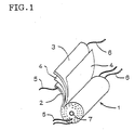
- a relatively large capacity lithium secondary battery suitable for an EV or HEV, etc. preferably uses as its electrode body a wound type electrode body 1 as shown in Fig. 1 made up of electrode plates (positive electrode plate 2 and negative electrode plate 3) to which current collector tabs (positive current collector tab 5, negative current collector tab 6) functioning as lead wires are attached, wound around a core 7 with a separator 4 inserted in between to prevent the two electrode plates from contacting each other.
- the positive electrode plate 2 and the negative electrode plate 3 are layers formed by applying respective electrode active materials (which refer to both positive active material and negative active material) to both surfaces of the current collector substrates such as metal foil.
- the positive current collector tab 5 and the negative current collector tab 6 can be attached to exposed metal foils at the ends of the positive electrode plate 2 and the negative electrode plate 3 at predetermined intervals using a suitable means such as ultrasonic welding during an operation wherein the positive electrode plate 2, and the negative electrode plate 3 are wound around the core 7, by sandwiching a separator 4.
- Batteries used for an EV or HEV or the like may be required not only to have a large capacity but also to produce an instantaneous discharge of high current especially at the time of starting the engine or climbing a slope, etc. That is, the development of batteries having a characteristic of high in critical discharge current is required.
- the separator does not always have excellent wettability for the non-aqueous electrolyte, that is, affinity or permeability, which is considered to cause not a little influence on characteristics of the battery.
- JP-A-2001-6747 discloses a non-aqueous electrolyte secondary battery which uses paper having predetermined physical properties as a separator and improves battery characteristics. Even the non-aqueous electrolyte secondary battery described in the above publication does not provide sufficient performance as a battery for which a discharge of instantaneous high current is required. Furthermore, a battery which is supposed to be installed and used under a low-temperature condition, for example, a vehicle-mounted battery, etc. needs to demonstrate sufficient battery characteristics even under such a condition and therefore there is a demand for further improvements.
- the present invention has been achieved in view of such problems of the conventional arts and it is an object of the present invention to provide a lithium secondary battery with a high critical discharge current even under a low-temperature condition, a satisfactory cycle characteristic and reduced manufacturing cost.
- a lithium secondary battery includes a wound type electrode body comprising a positive electrode plate, and a negative electrode plate both of which have been wound around a core via a separator; said electrode body being impregnated with a non-aqueous electrolyte, and a cylindrical case for housing the electrode body and the non-aqueous electrolyte; the case having at least one opening at either end thereof; said at least one opening being sealed, wherein the separator is subjected to drying treatment.
- the separator in the present invention is preferably made of paper.
- the paper be substantially made of cellulose, cellulose derivative or a mixture thereof.
- the drying treatment is preferably heat treatment and the heat treatment is preferably treatment using high frequency heating or microwave heating and further the dielectric heat treatment is preferably performed by applying high frequency or microwave to the positive electrode plate and negative electrode plate after the wound type electrode body is housed in the battery case, but before the non-aqueous electrolyte is injected.
- drying treatment is preferably performed with the wound type electrode body wound and furthermore with the wound type electrode body housed in the battery case.
- the inside of the battery case is preferably subjected to decompression processing through the opening the moment the drying treatment is performed and the decompression processing is preferably followed by injection of the non-aqueous electrolyte into the battery case.
- the number of openings installed in the battery case for the present invention is preferably one and the core is preferably a hollow-body and the opening is preferably provided at a position corresponding to the center axis of the core.
- the opening in the present invention is preferably an inlet of the non-aqueous electrolyte and a sealing member for sealing the opening is preferably provided with a pressure-releasing hole.
- the lithium secondary battery according to the present invention is suitable for a large capacity battery having a cell capacity of 2 Ah or more and preferably usable as a power supply for driving the motor of an electric vehicle or hybrid electric vehicle in which a high current frequently discharges.
- a lithium secondary battery comprising a wound type electrode body being composed of a positive plate and a negative plate wound around a core by sandwiched a separator therebetween; said electrode body being housed in a cylindrical battery case having at least one opening at either end thereof, and impregnated with a non-aqueous electrolyte; said al least opening being sealed, wherein the separator is subjected to drying treatment.
- Fig. 1 is a perspective view showing a structure of the wound type electrode body, which comprises a positive electrode plate 2 and a negative electrode plate 3 provided with positive electrode current collector tabs 5, and negative electrode current collector tabs 6 that function as a lead wire, respectively; said two electrode plates having been wound around a core 7 by sandwiching a separator 4 therebetween to prevent the electrode plates from contacting each other.
- the lithium secondary battery according to the present invention is characterized in that the separator 4 is subjected to drying treatment.
- the use of the separator subjected to drying treatment prevents movements of lithium ions of the electrolyte from being interfered and prevents polarization.
- this embodiment has a feature of demonstrating a good charge/discharge cycle characteristic (which refers to a cell capacity variation characteristic due to repeated charges and discharges and hereinafter referred to as "cycle characteristic").
- the material of the separator 4 examples include a general porous polymer, for example, a 3-layer structure (hereinafter referred to as "polyolefin 3-layer structure") with Li + permeable polyethylene film (PE film) sandwiched by porous Li + permeable polypropylene films (PP films) or paper, etc.
- the separator is preferably made of paper. Using paper as the separator has an effect of being higher in a critical discharge current than the separator made of general porous polymer.
- the separator of the lithium secondary battery of the present invention is subjected to drying treatment, which minimizes generation of hydrogen fluoride in the battery system, demonstrating the effect of improving the cycle characteristic compared to a lithium secondary battery using a separator without drying treatment.
- the lithium secondary battery of the present invention using a separator made of paper not only demonstrates a characteristic of being high in a critical discharge current but also reduces the manufacturing cost.
- the paper composing the separator be substantially made of cellulose, cellulose derivative or a mixture thereof. These materials are cheap and easily available and those with micropores in appropriate size have physical properties suitable for the separator for the lithium secondary battery and are preferable in both aspects of a reduction of the manufacturing cost and improvement of battery characteristics.
- the separator may also be subjected to surface treatment using chemicals such as a surface active agent, depending on the kind of cellulose, or cellulose derivative used as a material therefor. Furthermore, cellulose or cellulose derivative may be subjected to surface treatment for the improvement of the resistance to the electrolyte, too.
- the positive electrode plate is prepared by coating a positive electrode active material to both sides of a current collector substrate.
- a metal foil such as aluminum foil or titanium foil is used which has good corrosion resistance against electro-chemical reaction at the positive electrode.
- a punched metal or a mesh made of such material may also be used.
- the positive electrode active material lithium transition metal compound oxides such as lithium manganate (LiMn 2 O 4 ), lithium cobaltite (LiCoO 2 ) and lithium nickelite (LiNiO 2 ) or the like are preferably used.
- carbon powder such as acetylene black
- acetylene black it is also preferable to add carbon powder such as acetylene black to the positive electrode active material as a conductive assistant and it can be added arbitrarily within a range of 2 to 10 mass percentage.
- lithium manganate having a cubic system spinel structure mainly composed of Li and Mn (hereinafter simply referred to as "lithium manganate”) as the positive electrode active material because this compound may reduce the resistance of the inner electrode body, when compared with the case where other positive electrode substances are used.
- the stoichiometrical composition of lithium manganate is expressed as LiMn 2 O 4 , but the present invention is not limited to such a stoichiometrical composition and LiM z Mn 2-z O 4 (where M is a substitution element and Z is an amount of substitution) is also suitably usable, which is obtained by substituting part of transition element Mn by two or more elements of at least one type of element selected from a group including Ti and other elements such as Li, Fe, Ni, Mg, Zn, B, Al, Co, Cr, Si, Sn, P, V, Sb, Nb, Ta, Mo and W.
- the Li/Mn ratio (mol ratio) is (1+Z)/(2-Z) wherein Z denotes the molar ratio of the element(s) used for the substitution if Li which has substituted Mn is excessive and 1/(2-Z) if a substitution element M other than Li has substituted Mn, and therefore Li/Mn ratio > 0.5 always results in all cases.
- lithium manganate whose Li/Mn ratio exceeds 0.5. This further stabilizes the crystalline structure compared to the case where a stoichiometrical composition is used, making it possible to obtain a battery with an excellent cycle characteristic.
- substitution element M Li becomes positive univalent ion, Fe, Mn, Ni, Mg and Zn become positive bivalent ions, B, Al, Co and Cr become positive trivalent ions, Si, Ti and Sn become positive tetravalent ions, P, V, Sb, Nb and Ta become positive pentavalent ions and Mo and W become positive hexavalent ions and these are elements which are intercrystallized into LiMn 2 O 4 , and there are also cases where Co and Sn are positive bivalent ions, Fe, Sb and Ti are positive trivalent ions, Mn is positive trivalent or positive tetravalent ion, Cr is positive tetravalent or hexavalent. Therefore, various substitution elements M can exist with mixed atomic valences and the amount of oxygen need not always be 4 as expressed in the stoichiometrical composition and these may also be missing within a range to maintain the crystalline structure or may also exist excessively.
- Application of the positive electrode active material is performed by coating a slurry or paste prepared by adding a solvent or a binder to powder of a positive electrode active material to the current collector substrate using a roll coater method, etc, and drying thus coated material. Then, press work, etc. is applied if necessary.
- the negative electrode plate can also be prepared in much the same way as for the positive electrode plate.
- a metal foil such as copper foil or nickel foil which has a good corrosion characteristic against electrochemical reaction of the negative electrode is used preferably.
- an amorphous type carbonaceous material such as soft carbon or hard carbon or artificial graphite or high graphite content carbon material such as natural graphite is used while fiber is ideally used as the high graphite content carbon material.
- Li + permeable porous polymer polyolefin 3-layer structure
- paper separator As the separator, as already described Li + permeable porous polymer (polyolefin 3-layer structure) or paper separator is suitably used.
- the PE film when the temperature of the electrode body rises, the PE film may be softened at approximately 130°C and micropores may burst, which also serves as a safety mechanism which suppresses movement of Li + , that is, reaction of the battery.
- sandwiching this PE film having a lower softening temperature even if the PE film is softened, it is possible to maintain the shape of the PP film, preventing contract or short-circuit between the positive electrode plate and negative electrode plate. Thus, the cell reaction is effectively suppressed, and the safety of the battery is attained.
- a carbonate-based solvent such as ethylene carbonate (EC), diethyl carbonate (DEC), dimethyl carbonate (DMC), propylene carbonate (PC) or a single solvent such as ⁇ -butyrolactone, tetrahydrofuran, acetonitrile or mixed solvent is suitable.
- a mixed solvent of a cyclic carbonate and a chain carbonate mixed at a desired mixing ratio can be used suitably.
- Examples of the electrolyte include lithium complex fluorine compound such as lithium hexafluoro phosphate (LiPF 6 ), lithium fluoroborate (LiBF 4 ) or lithium halogen compound such as lithium perchlorate (LiClO 4 ) and one, or two or more types of substances are dissolved into the above described organic solvent (mixed solvent). It is particularly preferable to use LiPF 6 which is resistant to oxidation and decomposition and provides high conductivity for the non-aqueous electrolyte.
- LiPF 6 lithium complex fluorine compound
- LiBF 4 lithium fluoroborate
- LiClO 4 lithium halogen compound
- LiPF 6 lithium perchlorate
- the separator used for the lithium secondary battery of the present invention is subjected to the aforementioned drying treatment and the drying treatment is preferably heat treatment, which is capable of efficiently removing water inevitably contained in a material for separator. It is preferred that the water content of the material for separator after drying treatment is within a range of 0.0001 ppm or less.
- current collector tabs are attached to the exposed parts free of electrode active materials of the respective electrode plates.
- foil-like tabs made of the same material as that of the current collector substrates of the respective electrode plates is used suitably.
- the current collector tabs can be attached to the electrode plates using ultrasonic welding or spot welding, etc.
- the heat treatment for drying the separator in the present invention is preferably dielectric heat treatment and more specifically, this dielectric heat treatment is preferably treatment using high frequency heating or microwave heating. Furthermore, the dielectric heat treatment is preferably performed by applying a high frequency or microwave to the positive electrode plate and negative electrode plate after the wound type electrode body is housed in the battery case and before the non-aqueous electrolyte is injected.
- the positive electrode plate and negative electrode plate of the wound type electrode body before the non-aqueous electrolyte is injected can be considered to form a capacitor with the separator placed in between. If a high frequency or microwave is applied to the positive electrode plate and negative electrode plate in this condition, only the separator is heated due to the dielectric constant and dielectric loss of the capacitor with the separator. That is, it is possible to efficiently use energy for heating of the separator to be dried compared to the drying treatment, etc. using an external heat source such as a heater.
- the wound type electrode body prepared is housed in the battery case and held in a stable place.
- the separator drying treatment is preferably performed with the wound type electrode body wound and with the wound type electrode body housed in the battery case.
- the separator drying treatment can be performed in a stage prior to winding, but there is a possibility that water will be absorbed again in a stage of subsequent winding operation, etc. To avoid such a situation, it is necessary to keep dry the whole battery assembly process after the drying treatment, but such an operation may be complicated.
- the wound type electrode body is prepared using the separator beforehand and drying treatment is applied with the wound type electrode body wound and with the wound type electrode body housed in the battery case, there will be no need to keep dry the whole battery assembly process, which will simplify the operation and reduce the manufacturing cost.
- the wound type electrode body creation process that is, the separator drying process and non-aqueous electrolyte impregnation process are executed as processes independent of one another
- the following battery assembly process can be assumed. That is, the assembly is completed by undergoing processes like (1) heating while performing decompression processing through the opening, (2) substitution of the inside of the battery case by dry air or nitrogen, etc., (3) injection of the non-aqueous electrolyte after sealing the opening with a temporary cover, etc., (4) second decompression processing, (5) impregnation of non-aqueous electrolyte in a vacuum, (6) sealing of the opening.
- the drying treatment be performed together with the decompression processing of the inside of the battery case through the opening because in this way the separator can be dried effectively and the decompression processing for subsequent impregnation with the non-aqueous electrolyte is performed at the same time. That is, since processes (2) to (4) of the above processes (1) to (6) are omitted, and therefore the battery assembly operation will be simplified and the manufacturing cost can thereby be reduced. This also has the effect of the possibility of simplifying the battery structure.
- the number of openings is preferably one in the present invention, because in this way the inside of the battery case can be fully decompressed and the structure of the battery, especially the structure of the part where the opening is provided (electrode cover, etc.) becomes simple.
- the opening in the present invention is preferably the inlet of the non-aqueous electrolyte, which makes it possible to dry paper with the inside of the battery case kept decompressed and impregnate the inside of the decompressed battery case with the non-aqueous electrolyte through the same opening.
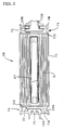
- Fig. 2 is a cross-sectional view showing an embodiment of the lithium secondary battery of the present invention.
- a wound type electrode body 61 is housed inside a cylindrical battery case 73, a current collector member 50 for leading out a current is attached to both ends of this wound type electrode body 61 and external terminals (positive electrode external terminal 70A, negative electrode external terminal 70B) are connected via electrode lead members 72.
- a core 67 which is a component of the wound type electrode body 61 be hollow and an opening be provided at a position corresponding to the center axis of the core 67 and furthermore, a blocking member for blocking the opening be provided with a pressure-releasing hole 75.
- Such a structure causes the pressure-releasing hole 75 to be placed in an extension of the center axis of the core 67 and even if an inner pressure increases, it is possible to decompress very speedily and uniformly, and therefore it is also preferable from the standpoint of not only the manufacturing cost but also securing safety.
- the positive electrode current collector tab 5 and negative electrode current collector tab 6 in the wound type electrode body 1 as shown in Fig. 1 are not essential members, but these can also have a structure as shown in Fig. 2 in which the positive and negative electrode plates making up the wound type electrode body 61 are directly connected to the collector member 50 and they can further have a structure in which the collector member 50 and internal terminals 69A and 69B are directly connected without the electrode lead member 72 inserted in between.
- the lithium secondary battery and its embodiments have been explained, but it goes without saying that the present invention is not limited to the above described embodiments.
- the lithium secondary battery according to the present invention is ideally applicable to a large battery with a cell capacity of 2 Ah or above, but this does not constitute any impediment to its application to a battery having a smaller capacity.
- the lithium secondary battery of the present invention is ideally applicable to a vehicle-mounted battery taking advantage of the large capacity, low cost and high reliability or is preferably applicable to a motor drive power supply for an electric vehicle or hybrid electric vehicle and is suitably used to start an engine requiring a high voltage.
- LiMn 2 O 4 spinel is used as a positive electrode active material, acetylene black of 4 mass % is added thereto as a conductive assistant and a solvent and binder are further added thereto to prepare positive electrode slurry.
- This positive electrode slurry is applied to both sides of an aluminum foil of 20 ⁇ m in thickness so as to form a film of approximately 100 ⁇ m in thickness to prepare a positive electrode plate, while graphite powder is used as a negative electrode active material and applied to both sides of a copper foil of 10 ⁇ m in thickness so as to form a film of approximately 80 ⁇ m in thickness to prepare a negative electrode plate.
- a separator made of 30- ⁇ m thick paper and a separator with a 30- ⁇ m thick polyolefin 3-layer structure (polypropylene (PP)/polyethylene (PE)/polypropylene (PP)) and an aluminum hollow core are prepared, the positive electrode plate and negative electrode plate are wound around the core with inserting the separator therebetween to create a wound type electrode body.
- this wound type electrode body is housed in a battery case, subjected to vacuum deaeration at 100°C under a pressure of 1 Pa for 24 hours and then subjected to full drying treatment (Embodiments 1 and 2).
- Organic solvents such as EC, DMC and EMC are mixed at a volume ratio of 1:1:1 to prepare a mixed solvent, electrolyte LiPF 6 is dissolved into this to reach a concentration of 1 mol/l, thus preparing a non-aqueous electrolyte.
- the battery case housing the wound type electrode body is filled with the non-aqueous electrolyte and the battery case is sealed to prepare an battery (Embodiments 1 and 2, Comparative examples 1 and 2). All batteries are manufactured by using a dry process. Furthermore, influences of water infiltration from outside the battery due to sealing defects, etc. of the battery are also excluded. The cell capacity after the initial charging of all batteries produced is approximately 8 Ah.
- a pulse cycle test was conducted for the lithium secondary batteries of above described Embodiments 1 and 2 and Comparative examples 1 and 2.
- One cycle was set to a pattern consisting of discharging a battery with depth of discharge of 50% at a current of 200 A corresponding to 20 C (discharge rate) for 3 seconds, then making a pause of 3 seconds, then charging at 200 A for 3 seconds and returning it to a 50% charged state.
- the capacity was measured with a charging stop voltage of 4.1 V and discharging stop voltage of 2.5 V with current strength of 1 C, the cell capacity after 20000 cycles was divided by the initial cell capacity and expressed in percentage to obtain a relative discharge capacity (%). Table 1 shows the results.
- the lithium secondary batteries according to Embodiments 1 and 2 still maintain high relative discharge capacity of 85% or above even after 20000 pulse cycle tests compared to the lithium secondary batteries in Comparative examples 1 and 2. Furthermore, it has also been discovered that the lithium secondary battery according to Embodiment 1 using a paper separator has not only a high relative discharge capacity but also a higher critical discharge current at -25°C than when a separator of a polyolefin 3-layer structure is used. Thus, advantages of the present invention could be confirmed.
- the lithium secondary battery of the present invention applies drying treatment to the separator, which is used as one of composition materials, and therefore it has a good cycle characteristic. It also has a high critical discharge current even under a low temperature condition and moreover the separator drying treatment is performed during the battery manufacturing process, and therefore it has excellent manufacturing efficiency and reduces the manufacturing cost. To provide a lithium secondary battery with a high critical discharge current even under a low temperature condition, with an excellent cycle characteristic and reduced manufacturing cost.
- This lithium secondary battery includes a wound type electrode body comprising a positive electrode plate, and a negative electrode plate both of which have been wound around a core via a separator; said electrode body being impregnated with a non-aqueous electrolyte, and a cylindrical case for housing the electrode body and the non-aqueous electrolyte; the case having at least one opening at either end thereof; said at least one opening being sealed.
- the separator is subjected to drying treatment before assembly.
Landscapes
- Chemical & Material Sciences (AREA)
- Chemical Kinetics & Catalysis (AREA)
- Electrochemistry (AREA)
- General Chemical & Material Sciences (AREA)
- Engineering & Computer Science (AREA)
- Manufacturing & Machinery (AREA)
- Secondary Cells (AREA)
- Cell Separators (AREA)
- Filling, Topping-Up Batteries (AREA)
- Sealing Battery Cases Or Jackets (AREA)
- Gas Exhaust Devices For Batteries (AREA)
- Battery Electrode And Active Subsutance (AREA)
Applications Claiming Priority (4)
| Application Number | Priority Date | Filing Date | Title |
|---|---|---|---|
| JP2001343552 | 2001-11-08 | ||
| JP2001343552 | 2001-11-08 | ||
| JP2002014362A JP4204231B2 (ja) | 2001-11-08 | 2002-01-23 | リチウム二次電池 |
| JP2002014362 | 2002-01-23 |
Publications (2)
| Publication Number | Publication Date |
|---|---|
| EP1311019A2 true EP1311019A2 (de) | 2003-05-14 |
| EP1311019A3 EP1311019A3 (de) | 2006-09-20 |
Family
ID=26624421
Family Applications (1)
| Application Number | Title | Priority Date | Filing Date |
|---|---|---|---|
| EP02024826A Withdrawn EP1311019A3 (de) | 2001-11-08 | 2002-11-07 | Lithiumsekundärbatterie |
Country Status (3)
| Country | Link |
|---|---|
| US (1) | US7135253B2 (de) |
| EP (1) | EP1311019A3 (de) |
| JP (1) | JP4204231B2 (de) |
Cited By (3)
| Publication number | Priority date | Publication date | Assignee | Title |
|---|---|---|---|---|
| EP2071646A4 (de) * | 2006-09-29 | 2010-10-27 | Shenzhen Bak Battery Co Ltd | Batteriekernhülle und batterie |
| EP2083461A4 (de) * | 2006-09-29 | 2010-10-27 | Shenzhen Bak Battery Co Ltd | Batteriehülle und batterie |
| EP2419946A4 (de) * | 2009-04-15 | 2013-08-21 | Johnson Controls Saft Advanced | Lüftung für elektrochemische zellen |
Families Citing this family (17)
| Publication number | Priority date | Publication date | Assignee | Title |
|---|---|---|---|---|
| US11050095B2 (en) | 2004-12-08 | 2021-06-29 | Maxell Holdings, Ltd. | Separator for electrochemical device, and electrochemical device |
| US20090093126A1 (en) * | 2005-09-13 | 2009-04-09 | Nxp B.V. | Method of and an apparatus for processing a substrate |
| JP4151852B2 (ja) | 2005-12-08 | 2008-09-17 | 日立マクセル株式会社 | 電気化学素子用セパレータとその製造方法、並びに電気化学素子とその製造方法 |
| JP4724223B2 (ja) * | 2006-09-07 | 2011-07-13 | 日立マクセル株式会社 | 電池用セパレータの製造方法 |
| US20080076018A1 (en) * | 2006-09-22 | 2008-03-27 | Wu Donald P H | Core Structure for a Circular Lithium Secondary Battery |
| CN101420048A (zh) * | 2007-10-26 | 2009-04-29 | 比亚迪股份有限公司 | 一种锂离子二次电池的制备方法 |
| KR101192056B1 (ko) * | 2008-02-05 | 2012-10-17 | 에스케이이노베이션 주식회사 | 파우치 타입 리튬 이차 전지 및 이의 제조 방법 |
| JP5547556B2 (ja) * | 2010-06-08 | 2014-07-16 | 大日本スクリーン製造株式会社 | 電池、車両、電子機器および電池の製造方法 |
| JP2013026149A (ja) * | 2011-07-25 | 2013-02-04 | Denso Corp | 組電池 |
| DE112013001480T5 (de) * | 2012-03-16 | 2015-04-09 | A 123 Systems, LLC | Mikrowellentrocknung von Lithium-Ionen Batterie Materialien |
| JP6492583B2 (ja) * | 2014-11-28 | 2019-04-03 | 株式会社豊田自動織機 | 電極の製造方法 |
| JP2016184521A (ja) * | 2015-03-26 | 2016-10-20 | オートモーティブエナジーサプライ株式会社 | 非水電解質二次電池 |
| KR102122804B1 (ko) * | 2016-12-21 | 2020-06-15 | 주식회사 엘지화학 | 전극의 건조 방법 |
| US10396315B2 (en) | 2016-12-30 | 2019-08-27 | Microsoft Technology Licensing, Llc | Hollow-core rolled-electrode battery cell |
| JP7219148B2 (ja) * | 2018-04-25 | 2023-02-07 | 住友化学株式会社 | 検査システム及び検査システムの駆動方法 |
| US20210399371A1 (en) * | 2020-06-23 | 2021-12-23 | Storedot Ltd | Temporary Cap for Electrochemical cell |
| CN112615089B (zh) * | 2020-12-17 | 2022-02-01 | 合肥国轩高科动力能源有限公司 | 一种锂电池卷芯、锂电池及制作方法 |
Citations (1)
| Publication number | Priority date | Publication date | Assignee | Title |
|---|---|---|---|---|
| JP2000012070A (ja) * | 1998-04-24 | 2000-01-14 | Sony Corp | 二次電池とその製造方法 |
Family Cites Families (8)
| Publication number | Priority date | Publication date | Assignee | Title |
|---|---|---|---|---|
| CA2106066C (en) | 1991-09-13 | 1997-08-12 | Akira Yoshino | Secondary battery |
| US5571632A (en) * | 1994-06-22 | 1996-11-05 | Sony Corporation | Nonaqueous electrolyte solution secondary cell and method for producing the same |
| US5849431A (en) * | 1995-09-27 | 1998-12-15 | Sony Corporation | High capacity secondary battery of jelly roll type |
| US5792517A (en) | 1996-04-25 | 1998-08-11 | Japan Vilene Company | Process for treating the outer-inner surfaces of a porous non-conductor |
| GB2320261B (en) * | 1996-11-11 | 2000-10-25 | Nippon Kodoshi Corp | Method of manufacturing highly-airtight porous paper, highly airtight porous paper manufactured by the method, and non-aqueous battery using the paper |
| JPH10162801A (ja) * | 1996-11-29 | 1998-06-19 | Nissan Motor Co Ltd | 二次電池 |
| US6468692B1 (en) * | 1999-06-08 | 2002-10-22 | Ngk Insulators, Ltd. | Lithium secondary battery with sealed casing members |
| JP2001006747A (ja) | 1999-06-22 | 2001-01-12 | Sony Corp | 非水電解液二次電池 |
-
2002
- 2002-01-23 JP JP2002014362A patent/JP4204231B2/ja not_active Expired - Fee Related
- 2002-11-04 US US10/287,182 patent/US7135253B2/en not_active Expired - Fee Related
- 2002-11-07 EP EP02024826A patent/EP1311019A3/de not_active Withdrawn
Patent Citations (1)
| Publication number | Priority date | Publication date | Assignee | Title |
|---|---|---|---|---|
| JP2000012070A (ja) * | 1998-04-24 | 2000-01-14 | Sony Corp | 二次電池とその製造方法 |
Cited By (4)
| Publication number | Priority date | Publication date | Assignee | Title |
|---|---|---|---|---|
| EP2071646A4 (de) * | 2006-09-29 | 2010-10-27 | Shenzhen Bak Battery Co Ltd | Batteriekernhülle und batterie |
| EP2083461A4 (de) * | 2006-09-29 | 2010-10-27 | Shenzhen Bak Battery Co Ltd | Batteriehülle und batterie |
| EP2419946A4 (de) * | 2009-04-15 | 2013-08-21 | Johnson Controls Saft Advanced | Lüftung für elektrochemische zellen |
| US8945740B2 (en) | 2009-04-15 | 2015-02-03 | Johnson Controls—SAFT Advanced Power Solutions LLC | Vent for electrochemical cell |
Also Published As
| Publication number | Publication date |
|---|---|
| US7135253B2 (en) | 2006-11-14 |
| JP4204231B2 (ja) | 2009-01-07 |
| EP1311019A3 (de) | 2006-09-20 |
| JP2003208924A (ja) | 2003-07-25 |
| US20030087158A1 (en) | 2003-05-08 |
Similar Documents
| Publication | Publication Date | Title |
|---|---|---|
| US7135253B2 (en) | High discharge current lithium secondary battery and method of manufacture | |
| US8367243B2 (en) | Lithium secondary battery | |
| US20080044727A1 (en) | Process for production of active material and electrode, active material, and electrode | |
| CA2347630A1 (en) | Charging method for charging nonaqueous electrolyte secondary battery | |
| JP5194633B2 (ja) | 活物質及び電極の製造方法、活物質及び電極 | |
| RU2644590C1 (ru) | Вспомогательный аккумулятор с неводным электролитом и способ изготовления вспомогательного аккумулятора с неводным электролитом | |
| JP2001283907A (ja) | リチウム二次電池 | |
| EP1278261A1 (de) | Nichtwässriger Elektrolyt und Batterie mit nichtwässrigem Elektrolyten | |
| JP2008066040A (ja) | 電池およびその製造方法 | |
| JP2001283921A (ja) | リチウム二次電池 | |
| JP2005285545A (ja) | リチウム二次電池 | |
| JP4678235B2 (ja) | 非水電解質二次電池 | |
| JP3594521B2 (ja) | リチウム二次電池の評価方法 | |
| JP3968772B2 (ja) | 非水電解質電池 | |
| JP3714259B2 (ja) | 非水電解質二次電池 | |
| KR101744382B1 (ko) | 이차전지용 전극 리드 및 이를 포함하는 이차전지 | |
| JP2000260469A (ja) | リチウム二次電池 | |
| JP2002352862A (ja) | 電極体の評価方法及びそれを用いたリチウム二次電池、並びにその製造方法 | |
| JP7719610B2 (ja) | リチウムイオン二次電池 | |
| JP4805545B2 (ja) | リチウム二次電池 | |
| JP2001283920A (ja) | リチウム二次電池 | |
| JP4938923B2 (ja) | 二次電池 | |
| JP4040264B2 (ja) | 電極体の評価方法 | |
| JP2004288405A (ja) | リチウム二次電池 | |
| JPH06333553A (ja) | 非水電解液二次電池 |
Legal Events
| Date | Code | Title | Description |
|---|---|---|---|
| PUAI | Public reference made under article 153(3) epc to a published international application that has entered the european phase |
Free format text: ORIGINAL CODE: 0009012 |
|
| AK | Designated contracting states |
Designated state(s): AT BE BG CH CY CZ DE DK EE ES FI FR GB GR IE IT LI LU MC NL PT SE SK TR |
|
| AX | Request for extension of the european patent |
Extension state: AL LT LV MK RO SI |
|
| PUAL | Search report despatched |
Free format text: ORIGINAL CODE: 0009013 |
|
| AK | Designated contracting states |
Kind code of ref document: A3 Designated state(s): AT BE BG CH CY CZ DE DK EE ES FI FR GB GR IE IT LI LU MC NL PT SE SK TR |
|
| AX | Request for extension of the european patent |
Extension state: AL LT LV MK RO SI |
|
| 17P | Request for examination filed |
Effective date: 20061114 |
|
| AKX | Designation fees paid |
Designated state(s): DE FR GB |
|
| 17Q | First examination report despatched |
Effective date: 20070807 |
|
| STAA | Information on the status of an ep patent application or granted ep patent |
Free format text: STATUS: THE APPLICATION IS DEEMED TO BE WITHDRAWN |
|
| 18D | Application deemed to be withdrawn |
Effective date: 20140311 |
|
| REG | Reference to a national code |
Ref country code: DE Ref legal event code: R079 Free format text: PREVIOUS MAIN CLASS: H01M0010400000 Ipc: H01M0010052000 |
|
| REG | Reference to a national code |
Ref country code: DE Ref legal event code: R079 Free format text: PREVIOUS MAIN CLASS: H01M0010400000 Ipc: H01M0010052000 Effective date: 20140818 |