EP1312276A1 - Spannvorrichtung, insbesondere für Sportschuhe - Google Patents
Spannvorrichtung, insbesondere für Sportschuhe Download PDFInfo
- Publication number
- EP1312276A1 EP1312276A1 EP02025017A EP02025017A EP1312276A1 EP 1312276 A1 EP1312276 A1 EP 1312276A1 EP 02025017 A EP02025017 A EP 02025017A EP 02025017 A EP02025017 A EP 02025017A EP 1312276 A1 EP1312276 A1 EP 1312276A1
- Authority
- EP
- European Patent Office
- Prior art keywords
- tightening device
- gearwheel
- pulley
- buckle
- box
- Prior art date
- Legal status (The legal status is an assumption and is not a legal conclusion. Google has not performed a legal analysis and makes no representation as to the accuracy of the status listed.)
- Withdrawn
Links
- 230000007246 mechanism Effects 0.000 claims abstract description 63
- 230000033001 locomotion Effects 0.000 claims abstract description 8
- 230000009471 action Effects 0.000 claims description 8
- 238000011084 recovery Methods 0.000 claims description 7
- 210000002683 foot Anatomy 0.000 description 14
- 210000001699 lower leg Anatomy 0.000 description 10
- 230000004913 activation Effects 0.000 description 4
- 230000009467 reduction Effects 0.000 description 4
- 238000004804 winding Methods 0.000 description 4
- 230000000386 athletic effect Effects 0.000 description 2
- 230000000694 effects Effects 0.000 description 2
- 239000003351 stiffener Substances 0.000 description 2
- 230000005540 biological transmission Effects 0.000 description 1
- 230000009849 deactivation Effects 0.000 description 1
- 238000003780 insertion Methods 0.000 description 1
- 230000037431 insertion Effects 0.000 description 1
- 210000002414 leg Anatomy 0.000 description 1
- 230000000670 limiting effect Effects 0.000 description 1
- 238000004519 manufacturing process Methods 0.000 description 1
- 230000007420 reactivation Effects 0.000 description 1
- 230000000284 resting effect Effects 0.000 description 1
- 210000004233 talus Anatomy 0.000 description 1
- 210000002303 tibia Anatomy 0.000 description 1
Images



Classifications
-
- A—HUMAN NECESSITIES
- A43—FOOTWEAR
- A43C—FASTENINGS OR ATTACHMENTS OF FOOTWEAR; LACES IN GENERAL
- A43C11/00—Other fastenings specially adapted for shoes
- A43C11/16—Fastenings secured by wire, bolts, or the like
-
- A—HUMAN NECESSITIES
- A43—FOOTWEAR
- A43C—FASTENINGS OR ATTACHMENTS OF FOOTWEAR; LACES IN GENERAL
- A43C11/00—Other fastenings specially adapted for shoes
- A43C11/16—Fastenings secured by wire, bolts, or the like
- A43C11/165—Fastenings secured by wire, bolts, or the like characterised by a spool, reel or pulley for winding up cables, laces or straps by rotation
-
- Y—GENERAL TAGGING OF NEW TECHNOLOGICAL DEVELOPMENTS; GENERAL TAGGING OF CROSS-SECTIONAL TECHNOLOGIES SPANNING OVER SEVERAL SECTIONS OF THE IPC; TECHNICAL SUBJECTS COVERED BY FORMER USPC CROSS-REFERENCE ART COLLECTIONS [XRACs] AND DIGESTS
- Y10—TECHNICAL SUBJECTS COVERED BY FORMER USPC
- Y10T—TECHNICAL SUBJECTS COVERED BY FORMER US CLASSIFICATION
- Y10T24/00—Buckles, buttons, clasps, etc.
- Y10T24/21—Strap tighteners
- Y10T24/2183—Ski, boot, and shoe fasteners
Definitions
- the present invention relates to a tightening device, which is particularly suitable for the closure of a sports shoe, such as a ski boot, a snowboard boot, a skate boot or the like.
- tightening devices for sport shoes usually comprise two or more pairs of buckles, which are arranged transversely to the shell and/or the cuff of the sports shoe, to allow a selectively adjustable tightening between the shoe flaps.
- buckles occupy considerable space, as a result of which they can also cause falls due to the accidental contact of the same with a protrusion in the ground or with an obstacle, with the consequent possibility of breaking or at the least damaging such buckles.
- U.S. patent No. 4.433.456 discloses a tightening device, particularly for ski boots, comprising a box-shaped body that may be connected with a first portion of the ski boot, a pulley pivotally connected inside the box-shaped body, at least one cable strand connected at one end to the pulley and windable on the same. At the other end, the cable strand is connected, externally to the box-shaped body, to a second portion of the ski boot.
- a rotating knob is connected to the exterior of the box-shaped body, designed to bring about a rotation of the pulley, mechanical means being provided between the knob and the pulley, so as to lock the pulley at a certain desired position, in one direction of rotation, and release the pulley in the opposite direction.
- U.S. patent No. 4.841.649 also by the same Applicant, discloses a tightening device that comprises a box-shaped body connected to a ski boot.
- the tightening device comprises a knob pivotally connected to the exterior of the box-shaped body, and interacting with mechanical means designed to transmit the motion to a first and a second pulleys that are freely pivotally mounted inside said box-shaped body.
- a first and a second cable strand of interconnection with portions of the boot, such as two opposing flaps or a tongue, are partially windable on the first and second pulleys.
- the aim of the present invention is to provide a tightening device, particularly for a sports shoe such as a ski boot, a snowboard boot, a skate boot or the like, which allows achieving an excellent fastening of the sports shoe around the foot of the user to be accomplished simply and quickly.
- Another object of the present invention is to provide a tightening device, which allows fastening to be accomplished easily even while wearing padded gloves.
- Another object of the present invention is to provide a tightening device, which allows effective fastening to be accomplished also without requiring the user to develop considerable force.
- a further object of the present invention is to provide a tightening device, with limited overall dimensions, thereby avoiding accidental impact with the snowy surface and with obstacles.
- Another object of the present invention is to provide a tightening device, which is structurally simple and has low manufacturing costs.
- a tightening device particularly for a sports shoe such as a ski boot, a snowboard boot, a skate boot or the like, characterised in that it comprises a first mechanism for transmitting movement to a second mechanism, which is operatively connected to at least a cable element for fastening the sports shoe, the first mechanism being activated by way of the manual activation of a third mechanism.
- the tightening device allows overcoming the mentioned drawbacks related to the prior art.
- the combined action of such first and second mechanisms allows providing an excellent fastening of the sports shoe.
- Such a fastening action can be easily controlled by the user through the mentioned third mechanism.
- the tightening device is designated by the reference number 1.
- the tightening device 1 will be described hereinafter with particular reference to its application to a ski boot 2. However, it is not intended to limit in any way the scope of the present invention. In fact, as will better appear hereinafter, the skilled person can easily adapt the tightening device, according to the present invention, for application to other kinds of sports shoes such as snowboard boots, skate boots or the like.
- the ski boot 2 comprises a shell 3, to which a cuff 4 that wraps around the lower portion of the leg is pivotally connected at the anklebone area.
- the shell 3 is provided, at the bottom, with a sole 5, advantageously comprising a normalised toe unit and a heel unit for the interconnection of a known type of ski binding.
- the shell 3 further has an opening 6 provided approximately in the area of the upper surface and instep of the foot. The opening 6 is delimited, at the front, by a stiffener 7 designed to retain the toe area of the foot and to accomplish the connection between a pair of lateral edges 8, which protrude from the top of the sole 5.
- the opening 6 is at least partially recloseable by means of a tongue 9, which is, at a first end, pivotally mounted to the stiffener 7, approximately above the toe area of the foot.
- An upper not shown in the figures, is advantageously arranged below the tongue 9 and between the pair of lateral edges 8, so as to wrap around at least the instep of the foot.
- a soft liner 10 to retain the user's foot is then suitably arranged inside the shell 3 and the cuff 4.
- a fastening buckle 11 is also preferably provided, so as to allow the closure of the cuff 4 around the tibia area.
- the fastening device 1 comprises a first box-shaped body 12, which is, in this particular embodiment, operatively associated to the boot 2 approximately to the rear of the cuff 4.
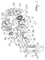
- the first box-shaped body 12 advantageously consists of a first and a second shell, respectively designated by reference numbers 13a and 13b, that may be coupled to each other for example by means of a first pin or screw 14.
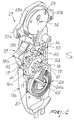
- the first box-shaped body 12 is aimed at including and protecting a first mechanism 15 for movement transmission, which comprises a first gearwheel and a second gearwheel, respectively 16a and 16b, and a first pulley 17.
- the first and second gearwheels 16a and 16b and the first pulley 17 are advantageously made in a single body.
- the first gearwheel 16a has a larger diameter than the second gearwheel 16b.
- the first pulley 17 is preferably positioned at the front of the first gearwheel 16a and therefore in an opposite position to the second gearwheel 16b.
- the first and the second gearwheels 16a and 16b and the pulley 17 are pivotally mounted inside the first box-shaped body 12, preferably through a first axial hole 18, approximately counter-shaped to the first pin 14 and interacting in a rotating manner
- the second gearwheel 16b engages a third gearwheel 19, preferably having a greater diameter, in order to have a reduction ratio of gear of more than one.
- the third gearwheel 19 is advantageously made in a single body with a second pulley 10, arranged to the rear.
- the third gearwheel 19 and the second pulley 20 form a second mechanism 21, which interacts with the first mechanism 15.
- the second mechanism 21 is advantageously pivotally connected to the first front shell 13a, preferably by means of a second pin 22.
- a first resilient element 24 is arranged to the rear of the second pulley 20, such as a first spring for example of the spiral type, housed in a first seat 25 provided in the second shell 13b.
- the first spring 24, lying coaxially to the second pin 22, is operatively connected, at one end, to the pulley 20, in the seat 24a, and, at the other end, to the second shell 13b, in the seat 24b, in such a way as to oppose, by preloading, a clockwise rotation of the second mechanism 21 (according to the view of figure 3).
- a first cable element 26 may be wound, at least partially on the second pulley 20. The first cable 26 outcomes from the fastening device 1 in such a way as to involve the tongue 9 and the side edges 8 of the shell 3.
- the first cable element 26 may advantageously run, as shown in figure 1, on top of the tongue 9 and inside the shell 3, within appropriate second seats, not shown in detail.
- the first cable 26 is connected to one of the side edges 8 in such a way that upon a rotation of the second pulley 20 such first cable 26 is pulled with the consequent approach between the pair of side edges 8 and the tongue 9 and, therefore, performing the fastening of the boot 2.
- the first cable 26 is wound, at least partially, onto the second pulley 20 in such a way as to be put into traction by a clockwise rotation of the pulley 20, as shown in figure 3.
- the fastening of the ski boot 2 may be achieved through a rotation of the first mechanism 15 in a counter-clockwise direction, resulting in a clockwise rotation of the second mechanism 21 and the simultaneous partial winding of the first cable 26 on the second pulley 20.
- the rotation of the first mechanism 15 may be obtained by way of the manual activation of a third mechanism 27, arranged externally to the box-shaped body 12.
- the third mechanism 27 is arranged in a second box-shaped body 270, positioned above the box-shaped body 12 so that it may be easily gripped by the user.
- the second box-shaped body 270 comprises a third shell 28a and a fourth shell 28b, aimed at containing and supporting an internal third pulley 29.
- the third shell 28a and the fourth shell 28b have an approximately triangular configuration, with a pair of spurs 30a and 30b respectively, which protrude laterally, so as to form a handle or easy gripping means for the user.
- the third pulley 29 is axially and pivotally mounted on a third pin 31, which protrudes from the fourth shell 28b and passes through a third axial hole 32, provided in the third pulley 29.
- the third pulley 29 has a second seat 33, which is provided axially at the front face and which houses a second resilient element, such as a second spring 34.
- the second spring 34 for example of the spiral type, is joined at the ends to the third pulley 29, in the seat 34a, and to the third pin 31, in the seat 34b, in such a way as to become preloaded upon a counter-clockwise rotation of the third pulley 29 (according to the view of figure 3).
- a second cable element 35 is wound between the first pulley 17 and the third pulley, and defines a means of interconnection between these pulleys.
- the second cable 35 is wound on the third and first pulleys 29 and 17, preferably to a greater extent around the first pulley 17.
- the upwards pull of the third mechanism 27 causes a first unwinding of the second cable strand 35 wound on the third pulley 29, with preloading of the second spring 34, and then a second unwinding of the second cable 35 from the first pulley 17.
- This second unwinding is made possible by the counter-clockwise rotation of the first mechanism 15, which transmits the movement to the second mechanism 21.
- the locking and release means 36 shown in detail in figures 5-7, advantageously consist of a buckle 37, approximately "T" shaped, and therefore formed by a head 38a, of substantially triangular shape, from which a shank 38b protrudes.
- the shank 38 is transversely and pivotally mounted between the first and second shells 13a and 13b by means of a fourth pin 39, arranged above the first mechanism 15.
- a third resilient element is provided advantageously consisting of a third spring 50, for example of the coil type, operatively joined at the ends between the first free end 40 of the buckle 37 and a separating plate 51, integral with the box-shaped body 12.
- the head 38a of the buckle 37 protrudes externally to the box-shaped body 12, in such a way as to be reachable by the user for manual activation. Pressing downwards on the head 38a, which can slide along the curved surface 41, results in a clockwise rotation of the buckle 37, permitting deactivation of the same (figures 6 and 7).
- the first spring 24 preloaded, exerts a rotation, in opposite directions, both on the second and on the first mechanism 21 and 15, with consequent unwinding (loosening) of the first cable strand 26 and winding of the second cable strand 35 on the second pulley 20 and the first pulley 17.
- the torque developed by the first spring 24 should be greater than the resisting torque of the second spring 34 multiplied by the reduction ratio of gear between the first and the second gearwheels 16a and 16b, to which the frictions of the whole kinematic motion should be added.
- the small lever 42 acts as "second click". In fact, it is kept in contact with the profile of the gearwheel 16a by means of a fourth resilient element, the latter also being preferably formed by a fourth coil spring 44, which is joined, at one end, to the upper edge of the small lever 42 and, at the other end, to the shank 38b.
- the second free end 45 of the small lever 42 is inserted between two subsequent teeth, thereby preventing the buckle 37 from turning and permitting the repositioning of the first end 40 of the shank 38b in contact with the first gearwheel 16a.
- the third mechanism 27 which controls the fastening force on the ski boot 2
- the user exerts a counter-clockwise rotation on the first mechanism 15.
- the first movement of the first gearwheel 16a exerts on the small lever 42, such a force as to cause a counter-clockwise rotation of the buckle 37, which is thus returned to the original position with the first free end 40 in contact with the profile of the first gearwheel 16a (fig. 5).
- a reduction ratio of gear between the gearwheels 16a and 16b of preferably more than two is used.
- this ratio corresponds to 2.5 (twenty teeth for the larger wheel, eight for the smaller one).
- Operation of the invention is therefore as follows. Once the user has introduced his foot into the ski boot 2, he may achieve closure of the same by simply pulling the third control mechanism 27 upwards. After a first unwinding of the second cable 35 from the third pulley 29, causing a further loading of the second spring 34, there is the rotation in a counter-clockwise direction of the first mechanism 15 and in a clockwise direction of the second mechanism 21. There is consequently the recovery of a part of the first cable 26, which is previously arranged to involve the lateral edges 8 of the shell 3 and the tongue part 9, particularly in the area of the upper surface of the foot. During the clockwise rotation of the second mechanism 21, not only the first cable 26 returns, but the first spring 24 is also preloaded at the same time.
- the recovery of the first cable 26 implies the fact that the first cable 26 itself exerts a tightening force on the flaps 8 and the tongue 9.
- the buckle 37 remains resting on the first gearwheel 16a (as in figure 5), the first end 40 of the shank 38b allowing a free rotation of the first gearwheel 16a only in the boot tightening direction, and therefore in a counter-clockwise direction.
- the user releases the third mechanism 27, which returns to the original position by way of the returning action, accomplished by the previously preloaded second spring 34, of the second cable 35 on the third pulley 29.
- the first free end 40 of the shank 38b of the buckle 37 is inserted between the teeth of the first gearwheel 16a, preventing a clockwise rotation of the same by the preloaded first spring 24 of the second mechanism 21.
- the desired level of the tightening force is maintained during the sports activity and the closure of the ski boot is completed.
- the user may open the boot by means of the head 38a of the buckle 37 so that the latter is turned clockwise, disengaging the teeth of the first wheel 16a from the first free end 40 of the shank 38b.
- the first spring 24, free to release, sets in rotation the first, second and third pulley according to the respective speed ratios, thereby causing the partial winding of the second cable 35 on the first pulley 17 and the complete loosening of the first cable 26 on the second pulley 20, which permits the opening of the footwear and the foot to be taken out.
- the buckle 37 remains automatically in the rest position thanks to the action of the spring 50 (as in figure 6), and therefore the first end 40 of the shank 38b does not engage the teeth of the first gearwheel 16a.
- the third mechanism 27 upon a first counter-clockwise rotation of the first mechanism 15, the small lever 42 is expelled from the teeth of the first gearwheel and the buckle 37 is simultaneously reset in the locking position.
- the tightening device is provided with a control mechanism, consisting of a handle, which may be easily activated by the user, since it does not require the use of excessive force, and may also be accomplished while wearing gloves.
- the tightening device allows avoiding any accidental contact with the snowy surface or with posts, in particular when accomplishing a turn or during a slalom race.
- a fastening device 1 may be used with ski boots comprising shell and/or cuff fitted with overlapping flaps, or with other athletic sports shoes, such as snowboard boots, ice skating or roller skating boots that in any case have flaps to be joined or brought together.
- the handle formed by the third and the fourth shells 30a and 30b may have different shapes; in the described example, the lateral spurs 30a and 30b provide the user with a comfortable, safe grip, also while wearing gloves.
- the handle may have an opening or a projection designed to aid the insertion of one or more fingers, in any case achieving in an excellent way the proposed aims and objects.
- the use of the second gearwheel 16b can be avoided.
- the first wheel 16a engages directly the third gearwheel 19.
- the necessary force for accomplishing the tightening will be greater, since the reduction ratio of gear is unitary.
Landscapes
- Footwear And Its Accessory, Manufacturing Method And Apparatuses (AREA)
Applications Claiming Priority (2)
| Application Number | Priority Date | Filing Date | Title |
|---|---|---|---|
| ITTV20010152 | 2001-11-20 | ||
| IT2001TV000152A ITTV20010152A1 (it) | 2001-11-20 | 2001-11-20 | Dispositivo di serraggio particolarmente per una calzatura sportiva |
Publications (1)
| Publication Number | Publication Date |
|---|---|
| EP1312276A1 true EP1312276A1 (de) | 2003-05-21 |
Family
ID=11460149
Family Applications (1)
| Application Number | Title | Priority Date | Filing Date |
|---|---|---|---|
| EP02025017A Withdrawn EP1312276A1 (de) | 2001-11-20 | 2002-11-08 | Spannvorrichtung, insbesondere für Sportschuhe |
Country Status (3)
| Country | Link |
|---|---|
| US (1) | US20030093882A1 (de) |
| EP (1) | EP1312276A1 (de) |
| IT (1) | ITTV20010152A1 (de) |
Cited By (2)
| Publication number | Priority date | Publication date | Assignee | Title |
|---|---|---|---|---|
| WO2009068503A1 (en) * | 2007-11-26 | 2009-06-04 | Northwave S.R.L. | A closing device for an item of sports footwear |
| IT201700068746A1 (it) * | 2017-06-21 | 2018-12-21 | Northwave S R L | Dispositivo di serraggio |
Families Citing this family (30)
| Publication number | Priority date | Publication date | Assignee | Title |
|---|---|---|---|---|
| US7281341B2 (en) | 2003-12-10 | 2007-10-16 | The Burton Corporation | Lace system for footwear |
| US7516976B2 (en) * | 2005-08-29 | 2009-04-14 | The Burton Corporation | Strap for snowboard boots or bindings |
| US7306241B2 (en) * | 2005-08-29 | 2007-12-11 | The Burton Corporation | Strap for snowboard boots or bindings |
| CN101528540B (zh) * | 2006-12-08 | 2012-10-10 | 贝尔直升机泰克斯特龙公司 | 跨越叶片俯仰角控制系统 |
| US7648404B1 (en) * | 2007-05-15 | 2010-01-19 | John Dietrich Martin | Adjustable foot strap and sports board |
| WO2009139893A1 (en) | 2008-05-15 | 2009-11-19 | Ossur Hf | Circumferential walker |
| EP2317960A1 (de) | 2008-05-15 | 2011-05-11 | Ossur HF | Orthopädische vorrichtungen mit drehspannung |
| WO2010027407A1 (en) * | 2008-08-27 | 2010-03-11 | Ossur Hf | Rotary tensioning device |
| WO2012109524A1 (en) | 2011-02-10 | 2012-08-16 | Ossur Hf | Tightening system for an orthopedic article |
| CA2874232C (en) * | 2012-11-30 | 2018-02-27 | Puma SE | Rotary closure for a shoe |
| US8955199B2 (en) * | 2013-02-13 | 2015-02-17 | Tzy Shenq Enterprise Co., Ltd. | Shoelace fastener |
| ITTV20130045A1 (it) * | 2013-04-09 | 2014-10-10 | Northwave Srl | Dispositivo di serraggio |
| EP3046435B1 (de) | 2013-09-18 | 2020-04-15 | Ossur Iceland EHF | Einlegesohle für eine orthopädische vorrichtung |
| US9839548B2 (en) | 2013-09-25 | 2017-12-12 | Ossur Iceland Ehf | Orthopedic device |
| US9668907B2 (en) | 2013-09-25 | 2017-06-06 | Ossur Iceland Ehf | Orthopedic device |
| US9839549B2 (en) | 2013-09-25 | 2017-12-12 | Ossur Iceland Ehf | Orthopedic device |
| US9839550B2 (en) | 2013-09-25 | 2017-12-12 | Ossur Hf | Orthopedic device |
| WO2015089261A1 (en) | 2013-12-12 | 2015-06-18 | Ossur Hf | Outsole for orthopedic device |
| USD729393S1 (en) | 2014-03-27 | 2015-05-12 | Ossur Hf | Outsole for an orthopedic device |
| USD742017S1 (en) | 2014-03-27 | 2015-10-27 | Ossur Hf | Shell for an orthopedic device |
| USD744111S1 (en) | 2014-03-27 | 2015-11-24 | Ossur Hf | Orthopedic device |
| US9763808B2 (en) | 2014-05-19 | 2017-09-19 | Ossur Hf | Adjustable prosthetic device |
| US10512305B2 (en) | 2014-07-11 | 2019-12-24 | Ossur Hf | Tightening system with a tension control mechanism |
| US10182935B2 (en) | 2014-10-01 | 2019-01-22 | Ossur Hf | Support for articles and methods for using the same |
| US10391211B2 (en) | 2015-01-26 | 2019-08-27 | Ossur Iceland Ehf | Negative pressure wound therapy orthopedic device |
| US12156825B2 (en) | 2018-02-02 | 2024-12-03 | Ossur Iceland Ehf | Orthopedic walker |
| EP4247308B1 (de) | 2020-11-19 | 2025-12-24 | Ossur Iceland Ehf | Orthopädische gehhilfe |
| CN114906374A (zh) * | 2021-02-09 | 2022-08-16 | 陈臆霙 | 紧固装置及系线收放方法 |
| WO2023048661A1 (en) * | 2021-09-24 | 2023-03-30 | C.E.S. İleri̇ Kompozi̇t Ve Savunma Teknoloji̇leri̇ Sanayi̇ Ve Ti̇caret Anoni̇m Şi̇rketi̇ | The ratchet dial mechanism for helmet |
| TW202406824A (zh) * | 2022-08-01 | 2024-02-16 | 蔡志信 | 緊固裝置 |
Citations (11)
| Publication number | Priority date | Publication date | Assignee | Title |
|---|---|---|---|---|
| US3729779A (en) * | 1971-06-07 | 1973-05-01 | K Porth | Ski boot buckle |
| US4433456A (en) | 1981-01-28 | 1984-02-28 | Nordica S.P.A. | Closure device particularly for ski boots |
| IT1185291B (it) * | 1985-07-23 | 1987-11-04 | Nordica Spa | Dispositivo di bloccaggio del piede con gruppo di sbloccaggio automatico particolarmente per scarponi da sci |
| US4735004A (en) * | 1987-04-17 | 1988-04-05 | Lange International S.A. | Self-closing ski boot |
| EP0290847A2 (de) * | 1987-05-15 | 1988-11-17 | NORDICA S.p.A. | Schliess- und Anpassvorrichtung, insbesondere für Schistiefel |
| US4787124A (en) * | 1986-09-23 | 1988-11-29 | Nordica S.P.A. | Multiple-function actuation device particularly usable in ski boots |
| EP0297342A2 (de) * | 1987-07-03 | 1989-01-04 | NORDICA S.p.A. | Schliess- und Einstellungsvorrichtung, insbesondere für Skischuhe |
| EP0351653A2 (de) * | 1988-07-22 | 1990-01-24 | NORDICA S.p.A. | Halte- und Einstellvorrichtung, insbesondere für Schischuhe |
| US4961544A (en) * | 1988-11-09 | 1990-10-09 | Lange International S. A. | Cable tensioner with a winding drum for a ski boot |
| US5065481A (en) * | 1989-09-26 | 1991-11-19 | Raichle Sportschuh Ag | Clamping device for a ski boot |
| US5174051A (en) * | 1990-02-21 | 1992-12-29 | Raichle Sportschuh Ag | Ski boot with a rear closing device |
Family Cites Families (5)
| Publication number | Priority date | Publication date | Assignee | Title |
|---|---|---|---|---|
| IT8421234V0 (it) * | 1984-03-14 | 1984-03-14 | Nordica Spa | Manopola di azionamento a dimensioni ridotte per dispositivi di regolazione e chiusura, particolarmente in scarponi da sci. |
| IT1180988B (it) * | 1984-06-01 | 1987-09-23 | Caber Italia | Dispositivo di serraggio e regolazione particolarmente per scarponi da sci |
| IT1184540B (it) * | 1985-05-06 | 1987-10-28 | Nordica Spa | Scarpone da sci con dispositivo di chiusura dei gambali |
| IT209343Z2 (it) * | 1985-09-04 | 1988-10-05 | Nordica Spa | Struttura di dispositivo di azionamento per elementi di bloccaggio del piede particolarmente per scarponi da sci. |
| IT209252Z2 (it) * | 1985-12-24 | 1988-09-20 | Nordica Spa | Dispositivo di chiusura dei gambali di scarponi da sci. |
-
2001
- 2001-11-20 IT IT2001TV000152A patent/ITTV20010152A1/it unknown
-
2002
- 2002-11-07 US US10/289,271 patent/US20030093882A1/en not_active Abandoned
- 2002-11-08 EP EP02025017A patent/EP1312276A1/de not_active Withdrawn
Patent Citations (12)
| Publication number | Priority date | Publication date | Assignee | Title |
|---|---|---|---|---|
| US3729779A (en) * | 1971-06-07 | 1973-05-01 | K Porth | Ski boot buckle |
| US4433456A (en) | 1981-01-28 | 1984-02-28 | Nordica S.P.A. | Closure device particularly for ski boots |
| IT1185291B (it) * | 1985-07-23 | 1987-11-04 | Nordica Spa | Dispositivo di bloccaggio del piede con gruppo di sbloccaggio automatico particolarmente per scarponi da sci |
| US4787124A (en) * | 1986-09-23 | 1988-11-29 | Nordica S.P.A. | Multiple-function actuation device particularly usable in ski boots |
| US4735004A (en) * | 1987-04-17 | 1988-04-05 | Lange International S.A. | Self-closing ski boot |
| EP0290847A2 (de) * | 1987-05-15 | 1988-11-17 | NORDICA S.p.A. | Schliess- und Anpassvorrichtung, insbesondere für Schistiefel |
| EP0297342A2 (de) * | 1987-07-03 | 1989-01-04 | NORDICA S.p.A. | Schliess- und Einstellungsvorrichtung, insbesondere für Skischuhe |
| US4841649A (en) | 1987-07-03 | 1989-06-27 | Nordica S.P.A. | Locking and adjustment device particularly for ski boots |
| EP0351653A2 (de) * | 1988-07-22 | 1990-01-24 | NORDICA S.p.A. | Halte- und Einstellvorrichtung, insbesondere für Schischuhe |
| US4961544A (en) * | 1988-11-09 | 1990-10-09 | Lange International S. A. | Cable tensioner with a winding drum for a ski boot |
| US5065481A (en) * | 1989-09-26 | 1991-11-19 | Raichle Sportschuh Ag | Clamping device for a ski boot |
| US5174051A (en) * | 1990-02-21 | 1992-12-29 | Raichle Sportschuh Ag | Ski boot with a rear closing device |
Cited By (2)
| Publication number | Priority date | Publication date | Assignee | Title |
|---|---|---|---|---|
| WO2009068503A1 (en) * | 2007-11-26 | 2009-06-04 | Northwave S.R.L. | A closing device for an item of sports footwear |
| IT201700068746A1 (it) * | 2017-06-21 | 2018-12-21 | Northwave S R L | Dispositivo di serraggio |
Also Published As
| Publication number | Publication date |
|---|---|
| ITTV20010152A1 (it) | 2003-05-20 |
| US20030093882A1 (en) | 2003-05-22 |
Similar Documents
| Publication | Publication Date | Title |
|---|---|---|
| EP1312276A1 (de) | Spannvorrichtung, insbesondere für Sportschuhe | |
| US7661205B2 (en) | Automated tightening shoe | |
| JP5451604B2 (ja) | 自動締付け靴 | |
| US4596080A (en) | Alpine ski boot | |
| KR101853351B1 (ko) | 자동 조임 신발 | |
| US6892429B2 (en) | Brake device for a lace | |
| JPH0458961B2 (de) | ||
| EP2211654A1 (de) | Schliessvorrichtung für einen sportschuh | |
| CA2151549A1 (en) | Braking system for in-line skates | |
| EP1332689B1 (de) | Skischuh | |
| EP0945080B1 (de) | Hebelverschluss für Sportschuhe | |
| EP0351653B1 (de) | Halte- und Einstellvorrichtung, insbesondere für Schischuhe | |
| EP0363778A2 (de) | Automatisch lösbare Fusshaltevorrichtung, insbesondere für Schischuhe mit Hintereinstieg | |
| EP0434902B1 (de) | Einstellbare Verschlusseinrichtung speziell für Skistiefel | |
| US5107609A (en) | Ski boot with improved fit | |
| EP0645102B1 (de) | Verschlussvorrichtung, insbesondere für Sportschuhe | |
| JP2000189553A (ja) | スケ―ト靴用の制動装置 | |
| JP2003289901A (ja) | スノーボード用ブーツ | |
| EP1642514B1 (de) | Verschlussvorrichtung, insbesondere zur Befestigung der Klappen eines Sportschuhes | |
| EP0688510A1 (de) | Vorrichtung zum Einstellen der Position des Schaftes gegenüber der Schale eines Sportschuhs | |
| EP0410080A2 (de) | Fuss-Sicherheitseinrichtung insbesondere für Schistiefel | |
| EP4437896A1 (de) | Sportschuhe mit einer verriegelungsvorrichtung | |
| EP0433639A2 (de) | Halte- und Einstellvorrichtung, insbesondere für Skischuhe | |
| US20240041162A1 (en) | Operating device for a sports shoe or boot | |
| JP2807432B2 (ja) | スポーツ靴のシェルに対する脚部位置の調整装置 |
Legal Events
| Date | Code | Title | Description |
|---|---|---|---|
| PUAI | Public reference made under article 153(3) epc to a published international application that has entered the european phase |
Free format text: ORIGINAL CODE: 0009012 |
|
| AK | Designated contracting states |
Designated state(s): AT BE BG CH CY CZ DE DK EE ES FI FR GB GR IE IT LI LU MC NL PT SE SK TR |
|
| AX | Request for extension of the european patent |
Extension state: AL LT LV MK RO SI |
|
| RAP1 | Party data changed (applicant data changed or rights of an application transferred) |
Owner name: NORDICA S.P.A |
|
| AKX | Designation fees paid | ||
| REG | Reference to a national code |
Ref country code: DE Ref legal event code: 8566 |
|
| STAA | Information on the status of an ep patent application or granted ep patent |
Free format text: STATUS: THE APPLICATION IS DEEMED TO BE WITHDRAWN |
|
| 18D | Application deemed to be withdrawn |
Effective date: 20031122 |