EP1312579A2 - Manipulateur de matériaux avec un tableau électronique d' indication de la charge - Google Patents
Manipulateur de matériaux avec un tableau électronique d' indication de la charge Download PDFInfo
- Publication number
- EP1312579A2 EP1312579A2 EP02257474A EP02257474A EP1312579A2 EP 1312579 A2 EP1312579 A2 EP 1312579A2 EP 02257474 A EP02257474 A EP 02257474A EP 02257474 A EP02257474 A EP 02257474A EP 1312579 A2 EP1312579 A2 EP 1312579A2
- Authority
- EP
- European Patent Office
- Prior art keywords
- boom
- material handler
- control system
- signal
- boundary
- Prior art date
- Legal status (The legal status is an assumption and is not a legal conclusion. Google has not performed a legal analysis and makes no representation as to the accuracy of the status listed.)
- Withdrawn
Links
- 239000000463 material Substances 0.000 title claims abstract description 62
- 238000000034 method Methods 0.000 claims description 22
- 238000010276 construction Methods 0.000 description 1
- 230000007423 decrease Effects 0.000 description 1
- 238000007689 inspection Methods 0.000 description 1
- 230000003068 static effect Effects 0.000 description 1
- 239000010409 thin film Substances 0.000 description 1
- 230000000007 visual effect Effects 0.000 description 1
Images


Classifications
-
- E—FIXED CONSTRUCTIONS
- E02—HYDRAULIC ENGINEERING; FOUNDATIONS; SOIL SHIFTING
- E02F—DREDGING; SOIL-SHIFTING
- E02F3/00—Dredgers; Soil-shifting machines
- E02F3/04—Dredgers; Soil-shifting machines mechanically-driven
- E02F3/28—Dredgers; Soil-shifting machines mechanically-driven with digging tools mounted on a dipper- or bucket-arm, i.e. there is either one arm or a pair of arms, e.g. dippers, buckets
- E02F3/283—Dredgers; Soil-shifting machines mechanically-driven with digging tools mounted on a dipper- or bucket-arm, i.e. there is either one arm or a pair of arms, e.g. dippers, buckets with a single arm pivoted directly on the chassis
- E02F3/286—Dredgers; Soil-shifting machines mechanically-driven with digging tools mounted on a dipper- or bucket-arm, i.e. there is either one arm or a pair of arms, e.g. dippers, buckets with a single arm pivoted directly on the chassis telescopic or slidable
-
- B—PERFORMING OPERATIONS; TRANSPORTING
- B66—HOISTING; LIFTING; HAULING
- B66F—HOISTING, LIFTING, HAULING OR PUSHING, NOT OTHERWISE PROVIDED FOR, e.g. DEVICES WHICH APPLY A LIFTING OR PUSHING FORCE DIRECTLY TO THE SURFACE OF A LOAD
- B66F17/00—Safety devices, e.g. for limiting or indicating lifting force
- B66F17/003—Safety devices, e.g. for limiting or indicating lifting force for fork-lift trucks
-
- B—PERFORMING OPERATIONS; TRANSPORTING
- B66—HOISTING; LIFTING; HAULING
- B66F—HOISTING, LIFTING, HAULING OR PUSHING, NOT OTHERWISE PROVIDED FOR, e.g. DEVICES WHICH APPLY A LIFTING OR PUSHING FORCE DIRECTLY TO THE SURFACE OF A LOAD
- B66F9/00—Devices for lifting or lowering bulky or heavy goods for loading or unloading purposes
- B66F9/06—Devices for lifting or lowering bulky or heavy goods for loading or unloading purposes movable, with their loads, on wheels or the like, e.g. fork-lift trucks
- B66F9/065—Devices for lifting or lowering bulky or heavy goods for loading or unloading purposes movable, with their loads, on wheels or the like, e.g. fork-lift trucks non-masted
- B66F9/0655—Devices for lifting or lowering bulky or heavy goods for loading or unloading purposes movable, with their loads, on wheels or the like, e.g. fork-lift trucks non-masted with a telescopic boom
Definitions
- the invention relates to material handlers, and more particularly to material handlers with telescoping booms.
- Material handlers are vehicles that include telescoping booms which are used to lift and transport loads.
- a typical telescoping boom includes a rearward end that is coupled to a back end of the material handler and a forward end that extends toward a front end of the material handler.
- the telescoping boom is extendable between a retracted position where the forward end of the boom is approximately located adjacent to the front end of the material handler and an extended position where the forward end of the telescoping boom is extended away from the front end of the material handler.
- the telescoping boom is also pivotable with respect to material handler between a lowered position where the telescoping boom is substantially horizontal and adjacent to the material handler, and a raised position where the telescoping boom is angled upward from the back end of the material handler such that the forward end of the telescoping boom is raised above the material handler.
- the telescoping boom is typically equipped with a fork that is insertable underneath a load in order to raise the load and move it to another position.
- the load is moved relative to the material handler and therefore it is possible to locate the load into a position that will cause the material handler to become unbalanced and, in extreme circumstances, cause the material handler to roll over.
- operators of material handlers have historically referred to printed load charts.
- a typical load chart is illustrated in Fig. 1 and graphically displays safe combinations of extension distances and elevation angles for different load weights. For example, when the material handler is in a static condition, the operator can determine how far the telescoping boom can be safely extended by referencing the elevation angle of the boom and load weight on the chart.
- Some systems display the distance that the load is extended so that the operator can more accurately determine the other variables from the chart and other systems include warning signals that inform the operator when an unsafe condition exists.
- the electronic load chart of the present invention enhances forward stability by identifying when a material handler is operating at a stable loading condition and by accurately indicating when the material handler is operating close to an unstable loading condition based on a distance that a telescoping boom is extended and an angle that the boom is raised.
- the electronic load chart also increases the overall efficiency of an operator and the material handler by eliminating the need for the operator to flip through manual load charts to determine the safety of a loading condition and by providing the operator with a display that is based on automatically sensed parameters such as boom extension distance and boom angle.
- the present invention is directed to a material handler that includes a frame, a telescoping boom, a boom extension sensor, a boom angle sensor, and a control system.
- the telescoping boom is coupled to the frame, pivotable between a lowered and a raised position, and movable between a retracted and an extended position.
- the boom extension sensor generates a first signal that corresponds to the distance which the boom is extended.
- the boom angle sensor generates a second signal that corresponds to the angle which the boom is pivoted.
- the control system receives the signals and displays a cursor located at a position that is based on the first signal and the second signal.
- the present invention is also directed to a method of displaying a load relative to a material handler including providing a telescoping boom that is coupled to a frame.
- the telescoping boom is movable between a retracted and an extended position and pivotable between a lowered and a raised position.
- the method further includes sensing the distance that the telescoping boom is extended, generating a first signal based on the sensed distance, sensing the angle that the telescoping boom is pivoted, generating a second signal based on the sensed angle, and displaying a cursor at a position based on the first signal and the second signal.
- Fig. 2 illustrates a material handler 10 of the present invention.
- the material handler 10 includes a frame 12, and front and rear wheels 14, 16 supporting the frame 12 for movement over the ground.
- the frame 12 has front and back ends (right and left ends in Fig. 2).
- the material handler 10 includes an engine (not shown) that is operably coupled to the wheels 14, 16.
- the material handler 10 includes an operator's station 18 that is centrally located above the frame 12.
- the material handler 10 includes a telescoping boom 20 that is used to lift and transport loads.
- the telescoping boom 20 includes a rearward or lower end 22 that is coupled to the back end of the frame 12 and a forward or upper end 24 that extends toward the front end of the frame 12.
- the telescoping boom 20 is extendable between a retracted position and an extended position and pivotable between a lowered position and a raised position.
- the telescoping boom 20 is extended and pivoted by respective hydraulic cylinders (not shown) that are controlled by the operator from the operator's station 18.
- the telescoping boom 20 is equipped with an attachment 26 that is utilized to raise and move a load to another position.
- the attachment 26 can include a fork, bucket, truss boom, or any other attachment that is known to those of ordinary skill in the art.
- the material handler 10 also includes an extension sensor 28 and an angle sensor 30.
- the extension sensor 28 is located on the telescoping boom 20 and generates a first signal that corresponds to the distance that the boom 20 is extended from the retracted position.
- the angle sensor 30 is located on the lower end 22 of the extension boom 20 and generates a second signal that corresponds to the angle that the boom 20 is pivoted from the lowered position.
- the extension sensor 28 is a Spherosyn Transducer Assembly manufactured by Newall Electronics, Inc.
- the angle sensor 30 is an Accustar Ratiometric Clinometer manufactured by Schaevitz Sensors Co.
- the specific configurations of these sensors 28, 30 are not discussed in detail because sensors which generate signals that represent measured distances and angles are well known to those of ordinary skill in the art.
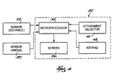
- the material handler 10 includes a control system 32 that has a controller 34, such as a microprocessor, and a screen 36.
- a controller 34 such as a microprocessor
- a screen 36 One such commercially available microprocessor is Part No. ELD1-1, which is manufactured by Orvitek.
- the controller 34 receives the first and second signals and displays on the screen 36 a cursor 38 that is located at a position that is based on the first signal and the second signal and that indicates the position of the forks 26.
- the cursor 38 can be any visual cue that identifies a position.
- the screen 36 is mounted in the operator's station 18 and is preferably a thin film electroluminescent display that is capable of displaying a wide range of graphics.
- the screen 36 also displays the cursor 38 relative to a boundary 40 that defines a safe zone 42 in which the material handler 10 is stable and an unsafe zone 44 in which the material handler 10 is unstable.
- the material handler 10 is likely to tip over when the material handler 10 is unstable. For example, when a load supported by the telescoping boom 20 is extended or raised beyond a certain condition, the material handler 10 will tip in the forward direction.
- the boundary 40 is shaped similar to a portion of the load chart in Fig. 1.
- a first dimension A is defined by the distance that the telescoping boom 20 is allowed to extend in the unloaded condition and a second dimension B is defined by the angles through which the telescoping boom 20 is allowed to pivot in the unloaded condition.
- the first signal determines the position of the cursor 38 along the first dimension A and the second signal determines the position of the cursor along the second dimension B.
- the location of the cursor 38 relative to the boundary 40 automatically changes as the position of the telescoping boom 20 changes. Accordingly, the operator is immediately informed by the location of the cursor 38 relative to the boundary 40 how far the telescoping boom 20 can be safely extended or raised.
- the control system 32 also includes an attachment selector 46 and a keypad 48.
- the attachment selector 46 is a switch that is selectively adjustable by the operator between a number of different positions 50. Each position 50 on the attachment selector 46 generates an attachment signal that corresponds to a different type of attachment 26.
- the control system 32 must differentiate between the differently shaped attachments 26 because the loads that are supported by the attachments 26 are positioned in different locations relative to the forward end 24 of the telescoping boom 20.
- the keypad 48 generates a weight signal that corresponds to a weight of the load that is entered by the operator.
- the controller 34 receives the attachment and weight signals and automatically varies the displayed boundary 40 based on the attachment and weight signals.
- the shape of the boundary 40 changes when the attachment signal changes and the size of the displayed boundary 40 decreases when the magnitude of the entered weight increases.
- the attachment signal is manually selected and the weight signal is manually entered, sensors that automatically generate the attachment and weight signals can also be used and are within the scope of the present invention.
Landscapes
- Engineering & Computer Science (AREA)
- Structural Engineering (AREA)
- Mechanical Engineering (AREA)
- Transportation (AREA)
- Civil Engineering (AREA)
- Life Sciences & Earth Sciences (AREA)
- Geology (AREA)
- Mining & Mineral Resources (AREA)
- General Engineering & Computer Science (AREA)
- Forklifts And Lifting Vehicles (AREA)
- Catching Or Destruction (AREA)
Applications Claiming Priority (2)
| Application Number | Priority Date | Filing Date | Title |
|---|---|---|---|
| US13051 | 2001-10-29 | ||
| US10/013,051 US6779961B2 (en) | 2001-10-29 | 2001-10-29 | Material handler with electronic load chart |
Publications (2)
| Publication Number | Publication Date |
|---|---|
| EP1312579A2 true EP1312579A2 (fr) | 2003-05-21 |
| EP1312579A3 EP1312579A3 (fr) | 2005-05-11 |
Family
ID=21758048
Family Applications (1)
| Application Number | Title | Priority Date | Filing Date |
|---|---|---|---|
| EP02257474A Withdrawn EP1312579A3 (fr) | 2001-10-29 | 2002-10-28 | Manipulateur de matériaux avec un tableau électronique d' indication de la charge |
Country Status (2)
| Country | Link |
|---|---|
| US (1) | US6779961B2 (fr) |
| EP (1) | EP1312579A3 (fr) |
Cited By (6)
| Publication number | Priority date | Publication date | Assignee | Title |
|---|---|---|---|---|
| FR2889513A1 (fr) * | 2005-08-02 | 2007-02-09 | Potain Soc Par Actions Simplif | Procede et dispositif de controle de la charge d'une grue a tour a fleche relevable |
| ITTO20100776A1 (it) * | 2010-09-23 | 2012-03-24 | Merlo Project Srl | Veicolo sollevatore |
| WO2012122581A1 (fr) * | 2011-03-16 | 2012-09-20 | Wacker Neuson Linz Gmbh | Dispositif de chargement utilisant un appareil de chargement télescopique |
| ITTO20110399A1 (it) * | 2011-05-06 | 2012-11-07 | Merlo Project Srl | Veicolo sollevatore |
| IT202100023042A1 (it) * | 2021-09-07 | 2023-03-07 | Magni Real Estate S R L | Procedimento di generazione di diagrammi di carico per sollevatori telescopici |
| IT202300011913A1 (it) * | 2023-06-12 | 2024-12-12 | Merlo Project Srl | Veicolo sollevatore multifunzionale e relativo dispositivo di visualizzazione intelligente |
Families Citing this family (11)
| Publication number | Priority date | Publication date | Assignee | Title |
|---|---|---|---|---|
| SE524739C2 (sv) * | 2002-07-15 | 2004-09-21 | Stock Of Sweden Ab | Truck |
| US7489098B2 (en) | 2005-10-05 | 2009-02-10 | Oshkosh Corporation | System for monitoring load and angle for mobile lift device |
| DE202005016489U1 (de) * | 2005-10-20 | 2007-03-01 | Liebherr-Hydraulikbagger Gmbh | Hydraulikbagger mit eingebauter Magnettraverse |
| US8449240B2 (en) * | 2010-10-13 | 2013-05-28 | Cnh America Llc | Round bale loader for transport frame |
| US9182270B2 (en) | 2012-05-14 | 2015-11-10 | Magnetek, Inc. | Method and apparatus for measuring a load in a material handling system |
| US10410124B1 (en) * | 2013-01-21 | 2019-09-10 | Link-Belt Cranes, L.P., Lllp | Display for displaying lifting capacity of a lifting machine and related methods |
| NL2015715B1 (nl) * | 2015-11-03 | 2017-05-24 | Ravas Europe B V | Hefvoertuig. |
| JP2018075121A (ja) * | 2016-11-08 | 2018-05-17 | ソニー株式会社 | 医療用支持アーム装置 |
| US10974702B2 (en) * | 2018-01-31 | 2021-04-13 | Spartan Fire, Llc | Multi-stance aerial device control and display |
| CN109132894B (zh) * | 2018-10-22 | 2020-12-08 | 徐州重型机械有限公司 | 起重设备 |
| EP4264316A1 (fr) | 2020-12-21 | 2023-10-25 | Oshkosh Corporation | Système et procédé de détermination de portée et de position |
Citations (1)
| Publication number | Priority date | Publication date | Assignee | Title |
|---|---|---|---|---|
| EP0420625A2 (fr) * | 1989-09-27 | 1991-04-03 | Kabushiki Kaisha Kobe Seiko Sho | Dispositif de sécurité pour une grue |
Family Cites Families (18)
| Publication number | Priority date | Publication date | Assignee | Title |
|---|---|---|---|---|
| US3641551A (en) | 1968-12-19 | 1972-02-08 | Grove Mfg Co | Safe load control system for telescopic crane booms |
| US3740534A (en) | 1971-05-25 | 1973-06-19 | Litton Systems Inc | Warning system for load handling equipment |
| DE2545427B2 (de) * | 1974-10-12 | 1979-05-03 | Liner Concrete Machinery Co. Ltd., Gateshead, Durham (Grossbritannien) | Fahrzeug zum Umsetzen von Lasten |
| US4216868A (en) | 1978-08-04 | 1980-08-12 | Eaton Corporation | Optical digital sensor for crane operating aid |
| US4218837A (en) * | 1978-08-21 | 1980-08-26 | Koehring Company | High lift hydraulic system for an excavator |
| US4583908A (en) * | 1980-02-21 | 1986-04-22 | Crawford Patrick J | Mobile device for handling material |
| US4516116A (en) * | 1981-12-16 | 1985-05-07 | Safety Devices (Engineering) Limited | Apparatus for visually displaying the load-moment, axle-load, or payload of a vehicle |
| US4544071A (en) | 1982-06-30 | 1985-10-01 | Fmc Corporation | External pendant pay-out system with anti-droop control |
| GB8406094D0 (en) * | 1984-03-08 | 1984-04-11 | Merryweather & Sons | Control system |
| US5730305A (en) * | 1988-12-27 | 1998-03-24 | Kato Works Co., Ltd. | Crane safety apparatus |
| US5058752A (en) | 1990-03-20 | 1991-10-22 | Simon-R.O. Corporation | Boom overload warning and control system |
| EP0466046A1 (fr) * | 1990-07-11 | 1992-01-15 | J.C. Bamford Excavators Limited | Disposition de capteur de charge |
| JPH07125987A (ja) | 1993-11-08 | 1995-05-16 | Komatsu Mec Corp | 移動式クレーンの吊り荷重、転倒モーメント検出装置 |
| GB9326347D0 (en) | 1993-12-23 | 1994-02-23 | Grove Europ Limited | Improvements in and relating to telescopic booms |
| JPH07187568A (ja) | 1993-12-28 | 1995-07-25 | Komatsu Ltd | クレーンの制御装置 |
| WO1996027548A1 (fr) * | 1995-03-03 | 1996-09-12 | Komatsu Ltd. | Dispositif destine a indiquer la plage de mobilite d'un vehicule a grue mobile |
| FR2750971B1 (fr) * | 1996-07-12 | 1998-10-02 | Fdi Sambron | Chariot de manutention pourvu d'un systeme de securite permettant d'eviter son basculement accidentel |
| US6041582A (en) * | 1998-02-20 | 2000-03-28 | Case Corporation | System for recording soil conditions |
-
2001
- 2001-10-29 US US10/013,051 patent/US6779961B2/en not_active Expired - Fee Related
-
2002
- 2002-10-28 EP EP02257474A patent/EP1312579A3/fr not_active Withdrawn
Patent Citations (1)
| Publication number | Priority date | Publication date | Assignee | Title |
|---|---|---|---|---|
| EP0420625A2 (fr) * | 1989-09-27 | 1991-04-03 | Kabushiki Kaisha Kobe Seiko Sho | Dispositif de sécurité pour une grue |
Cited By (10)
| Publication number | Priority date | Publication date | Assignee | Title |
|---|---|---|---|---|
| FR2889513A1 (fr) * | 2005-08-02 | 2007-02-09 | Potain Soc Par Actions Simplif | Procede et dispositif de controle de la charge d'une grue a tour a fleche relevable |
| EP1775252A1 (fr) * | 2005-08-02 | 2007-04-18 | Potain | Procédé et dispositif de contrôle de la charge d'une grue à tour à flèche relevable |
| AU2006203257B2 (en) * | 2005-08-02 | 2011-05-19 | Manitowoc Crane Group France | Method and device for adjusting the load of a luffing jib tower crane |
| ITTO20100776A1 (it) * | 2010-09-23 | 2012-03-24 | Merlo Project Srl | Veicolo sollevatore |
| WO2012122581A1 (fr) * | 2011-03-16 | 2012-09-20 | Wacker Neuson Linz Gmbh | Dispositif de chargement utilisant un appareil de chargement télescopique |
| ITTO20110399A1 (it) * | 2011-05-06 | 2012-11-07 | Merlo Project Srl | Veicolo sollevatore |
| EP2520536A1 (fr) * | 2011-05-06 | 2012-11-07 | Merlo Project S.r.l. | Véhicule de levage |
| IT202100023042A1 (it) * | 2021-09-07 | 2023-03-07 | Magni Real Estate S R L | Procedimento di generazione di diagrammi di carico per sollevatori telescopici |
| IT202300011913A1 (it) * | 2023-06-12 | 2024-12-12 | Merlo Project Srl | Veicolo sollevatore multifunzionale e relativo dispositivo di visualizzazione intelligente |
| EP4477612A1 (fr) * | 2023-06-12 | 2024-12-18 | Merlo Project S.r.l. | Véhicule de levage multifonctionnel et dispositif d'affichage intelligent associé |
Also Published As
| Publication number | Publication date |
|---|---|
| US20030082041A1 (en) | 2003-05-01 |
| US6779961B2 (en) | 2004-08-24 |
| EP1312579A3 (fr) | 2005-05-11 |
Similar Documents
| Publication | Publication Date | Title |
|---|---|---|
| US6779961B2 (en) | Material handler with electronic load chart | |
| US6985795B2 (en) | Material handler with center of gravity monitoring system | |
| AU2002336645A1 (en) | Material handler with center of gravity monitoring system | |
| EP1136433B1 (fr) | Chariot élévateur avec un dispositif de mesure du moment de la charge et procédé associé | |
| US9079756B2 (en) | Elevating platform and a method of controlling such a platform | |
| EP3249118B1 (fr) | Chargeuse sur pneus et procédé d'accumulation automatique pour informations de travail de transport de chargeuse sur pneus | |
| US7252203B2 (en) | Mobile crane having a superlift device | |
| US20230227300A1 (en) | Machine stability detection and indication for mobile lifting equipment | |
| EP3719223B1 (fr) | Machine de chantier et système incluant une machine de chantier | |
| EP3636582B1 (fr) | Machine, organe de commande et procédé de commande | |
| CN113460912B (zh) | 用于伸缩臂叉装车的模拟器 | |
| GB2437629A (en) | Display for assisting lift truck operator | |
| US5994650A (en) | Safety system for lift trucks | |
| KR102249671B1 (ko) | 작업 차량의 전도/전복 방지 시스템 및 방법 | |
| EP4077198B1 (fr) | Système et procédé de surveillance de grue et grue les comprenant | |
| EP4223687A2 (fr) | Commande d'opération de grue mobile | |
| JP7172443B2 (ja) | クレーン車 | |
| JP2002046998A (ja) | ブーム作業車の車体傾斜角検出装置 | |
| JP4015158B2 (ja) | クレーン吊荷操作表示装置 | |
| JPH10157984A (ja) | 作業機の作業状態表示装置 | |
| US3049257A (en) | Level indicator for fork type lift trucks | |
| KR20210155459A (ko) | 전도 방지를 위한 굴삭기 및 그 방법 | |
| US12601156B2 (en) | Work machine with operator display | |
| JP2000136097A (ja) | フォークリフトトラックにおけるリフト装置 | |
| KR20260058631A (ko) | 축중 모니터링 장치가 구비된 특장차 운전석 |
Legal Events
| Date | Code | Title | Description |
|---|---|---|---|
| PUAI | Public reference made under article 153(3) epc to a published international application that has entered the european phase |
Free format text: ORIGINAL CODE: 0009012 |
|
| AK | Designated contracting states |
Designated state(s): AT BE BG CH CY CZ DE DK EE ES FI FR GB GR IE IT LI LU MC NL PT SE SK TR |
|
| AX | Request for extension of the european patent |
Extension state: AL LT LV MK RO SI |
|
| PUAL | Search report despatched |
Free format text: ORIGINAL CODE: 0009013 |
|
| AK | Designated contracting states |
Kind code of ref document: A3 Designated state(s): AT BE BG CH CY CZ DE DK EE ES FI FR GB GR IE IT LI LU MC NL PT SE SK TR |
|
| AX | Request for extension of the european patent |
Extension state: AL LT LV MK RO SI |
|
| 17P | Request for examination filed |
Effective date: 20050817 |
|
| AKX | Designation fees paid |
Designated state(s): DE FR GB IT |
|
| STAA | Information on the status of an ep patent application or granted ep patent |
Free format text: STATUS: THE APPLICATION IS DEEMED TO BE WITHDRAWN |
|
| 18D | Application deemed to be withdrawn |
Effective date: 20060926 |