EP1312801A2 - Kraftstoffgekühltes Pumpenelement und Hochdruckpumpe für eine Kraftstoffeinspritzanlage - Google Patents
Kraftstoffgekühltes Pumpenelement und Hochdruckpumpe für eine Kraftstoffeinspritzanlage Download PDFInfo
- Publication number
- EP1312801A2 EP1312801A2 EP02017505A EP02017505A EP1312801A2 EP 1312801 A2 EP1312801 A2 EP 1312801A2 EP 02017505 A EP02017505 A EP 02017505A EP 02017505 A EP02017505 A EP 02017505A EP 1312801 A2 EP1312801 A2 EP 1312801A2
- Authority
- EP
- European Patent Office
- Prior art keywords
- pump
- piston
- fuel
- ring channel
- pressure fuel
- Prior art date
- Legal status (The legal status is an assumption and is not a legal conclusion. Google has not performed a legal analysis and makes no representation as to the accuracy of the status listed.)
- Withdrawn
Links
Images
Classifications
-
- F—MECHANICAL ENGINEERING; LIGHTING; HEATING; WEAPONS; BLASTING
- F04—POSITIVE - DISPLACEMENT MACHINES FOR LIQUIDS; PUMPS FOR LIQUIDS OR ELASTIC FLUIDS
- F04B—POSITIVE-DISPLACEMENT MACHINES FOR LIQUIDS; PUMPS
- F04B1/00—Multi-cylinder machines or pumps characterised by number or arrangement of cylinders
- F04B1/04—Multi-cylinder machines or pumps characterised by number or arrangement of cylinders having cylinders in star- or fan-arrangement
- F04B1/0404—Details or component parts
-
- F—MECHANICAL ENGINEERING; LIGHTING; HEATING; WEAPONS; BLASTING
- F04—POSITIVE - DISPLACEMENT MACHINES FOR LIQUIDS; PUMPS FOR LIQUIDS OR ELASTIC FLUIDS
- F04B—POSITIVE-DISPLACEMENT MACHINES FOR LIQUIDS; PUMPS
- F04B53/00—Component parts, details or accessories not provided for in, or of interest apart from, groups F04B1/00 - F04B23/00 or F04B39/00 - F04B47/00
- F04B53/08—Cooling; Heating; Preventing freezing
Definitions
- the invention relates to a pump element for a Piston pump according to the generic terms of the subordinate Claims 1 and 4 and a piston pump according to the General term of the secondary claim 7
- High pressure fuel pumps especially at High pressure fuel pumps of internal combustion engines with Gasoline direct injection, it is known that during the Operating temperatures so high that local Steam bubbles arise.
- These vapor bubbles are in several Regardless undesirable: First of all, steam bubbles in the Delivery space of the pump element (s) the delivery behavior of the high-pressure fuel pump. To the second, vapor bubble formation in the area of the Piston tread to tear off the lubricating film and thus lead to a piston seizure.
- the invention has for its object pump elements for a high pressure fuel pump and a high pressure fuel pump to provide that are simply constructed and the unwanted vapor bubble formation is reliable is avoided.
- This task is for a pump element for a Piston pump for high-pressure fuel generation Fuel injection systems of internal combustion engines, with at least one in a cylinder bore Cylinder bushing arranged piston, the Cylinder sleeve has a cylinder jacket and the Piston has a piston skirt, solved in that between the cylinder jacket and a pump housing Piston pump a first ring channel for cooling the Pump element is formed.
- Both embodiments are in terms of cooling performance as well as. It can be one or the other Embodiment depending on the other circumstances of the High-pressure fuel pump are preferred.
- Lubrication of the piston skirt in the cylinder bore can be significantly improved if in the piston skirt a second annular groove is provided and this second annular groove together with the cylinder bore a second ring channel for lubricating and cooling the piston.
- This one too second ring channel can of fuel, which of the Pre-feed pump is pumped, flowed through and thus cause cooling and lubrication of the piston. in the second ring channel prevails about the delivery pressure of the Pre-feed pump with a pressure corresponding to about 4 to 6 bar, as a result, the Evaporation temperature of the fuel increases what a additional security against the formation of steam bubbles offers.
- the so cooled and lubricated pistons of the pump element always by a stable lubricating film separated from the cylinder bore, see above that the piston is very low-wear in the Cylinder bore is guaranteed.
- a pump element for a piston pump High pressure fuel generation at Fuel injection systems of internal combustion engines with at least one in a cylinder bore Cylinder bushing arranged piston, the Cylinder sleeve has a cylinder jacket and the Piston has a piston skirt, solved in that in Piston shaft a second annular groove is provided and that the second ring groove together with the cylinder bore second ring channel for lubrication and cooling of the piston forms.
- This pump element has the advantages mentioned above a pump element with a second annular groove. It has showed that the existence of the second Ring groove and the second ring channel is sufficient for cooling and lubrication of the piston in all operating states ensure and the formation of steam bubbles to suppress effectively.
- Cylinder liner and piston can be provided in that Cylinder jacket a first annular groove is provided and that the first ring groove together with the pump housing Piston pump a first annular gap for cooling the Pump element forms.
- High-pressure fuel pump is provided for in the Pump housing a first hydraulic connection between a fuel supply on the one hand and the first Ring channel and / or the second ring channel on the other hand is available. Through this first hydraulic connection become the first ring channel and / or the second ring channel in a simple way of fuel, which of the Pre-feed pump conveyed to the high-pressure fuel pump is flowed through and thus the desired cooling occurs and lubrication of the cylinder liner and the piston.
- a quantity control valve be provided, which the tax amount in the first discharges hydraulic connection.
- the above The pressure damper also dampens that of the discharge quantity caused pressure surges on the suction side of the high-pressure fuel pump.
- a throttle is provided so that the drain of the pre-feed pump in the first and / or second Ring channel fuel is easily possible and the throttle, the amount of fuel, which by the flows first and / or second ring channel, as needed can be adjusted.
- the high-pressure fuel pump according to the invention is especially for use in those working according to the Otto principle Internal combustion engines, especially with direct petrol injection, suitable.
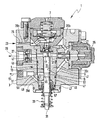
- the only figure shows an embodiment of a High-pressure fuel pump according to the invention in section.
- an embodiment is one High-pressure fuel pump 1 according to the invention Cross section shown.
- the High-pressure fuel pump 1 are a pump element 5 and a pressure damper 7 is used.
- the pump element 5 has et al a cylinder liner 9 and a piston 11 with a Piston shaft 13.
- the piston 11 is with his Piston shaft 13 in a cylinder bore 15 Cylinder bushing 9 out.
- a Pre-feed pump delivers fuel a fuel tank, also not shown, in the Fuel inlet 23.
- the delivery head of this prefeed pump is usually between 4 bar and 6 bar.
- the high pressure side 29 is with one or more injection nozzles, not shown hydraulically connected.
- the inlet valve 21 opens when the piston 11 is down from the inlet valve 21 removed, so that the volume of the delivery chamber 19 increases. As soon as the piston 11 reverses its direction of movement and the volume of the delivery chamber 19 is reduced again, that is Inlet valve 21 closed.
- the outlet valve 27 opens as soon as the pressure in the delivery chamber 19 is greater than on the high pressure side 29 of the high pressure fuel pump 1.
- the required oscillating motion of the piston 11 in the cylinder bore 15 is from one in the figure not shown drive, which on a second end 31 of the piston 11 acts, pronounced.
- This one Drive device not shown, can Camshaft in the cylinder head of the internal combustion engine, one Eccentric shaft or something comparable. So that Piston 11 impressed on it by the drive device oscillating movement in both directions between the second end 31 of the piston and the A compression spring 33 is clamped in the cylinder liner 9.
- the Compression spring 33 causes the second end 31 of the piston 11 always on the cam or the eccentric section the drive device rests.
- the delivery rate of the high-pressure fuel pump according to the invention is controlled by a volume control valve 35 controlled.
- the quantity control valve 35 is via a Connection bore 37 with the delivery chamber 19 hydraulically in Connection. Once the piston is out of fuel has conveyed the delivery chamber 19 to the high pressure side 29, opens the quantity control valve 35, so that the further from Piston 11 no longer delivered fuel High pressure side 29 arrives, but on the Connection bore 37 and a first hydraulic Connection 39 to the pressure damper 7 is promoted.
- the first hydraulic connection 39 has several Sections in the figure with 39a, 39b, 39c and 39d be designated.
- the discharge amount from the delivery room 19 flows through the connection bore 37 and the section 39b the first hydraulic connection to the pressure damper 7.
- the Fuel inlet 23 is the first over a section 39a hydraulic connection 39 in turn with the pressure damper 7 hydraulically connected. Over a section 39c of the first hydraulic connection 39 can not by the Pre-feed pump shown in the fuel inlet 23 in the fuel high-pressure pump 1 delivered fuel in a first ring channel 41 between a cylinder jacket 43 the cylinder liner 9 and a receiving bore 45 of the Flow the pump housing 3.
- the first ring channel 41 through a paragraph in the Cylinder jacket 43 and a paragraph in the stepped executed receiving bore 45 formed.
- fuel flows continuously from the fuel inlet 23 via the first hydraulic connection 39a, 39b and 39c. As a result, the cylinder liner 9 is cooled and as a result also the piston 11.
- the second ring channel 53 Leakage space 57 is provided, which has a second Connection bore 59 the amount of leakage to the fuel outlet 51 leads away. Between the throttle 49 and the Fuel drain 51 is a second hydraulic connection 61 is provided, into which the second connecting bore 59 empties. By dimensioning the throttle 49, the Fuel flow through the first hydraulic Connection 39 flows into the first ring channel 41, can be set.
- the second ring channel 53 is with the Form pressurized, which stabilizes the Lubricant film leads.
Landscapes
- Engineering & Computer Science (AREA)
- Mechanical Engineering (AREA)
- General Engineering & Computer Science (AREA)
- Fuel-Injection Apparatus (AREA)
- Structures Of Non-Positive Displacement Pumps (AREA)
Abstract
Description
Claims (13)
- Pumpenelement für eine Kraftstoff-Hochdruckpumpe (1) zur Kraftstoffhochdruckerzeugung bei Kraftstoffeinspritzsystemen von Brennkraftmaschinen, mit mindestens einem in einer Zylinderbohrung (15) einer Zylinderbuchse (9) angeordneten Kolben (11), wobei die Zylinderbuchse (9) einen Zylindermantel (43) aufweist und wobei der Kolben (11) einen Kolbenschaft (13) aufweist, dadurch gekennzeichnet, dass zwischen Zylindermantel (43) und einem Pumpengehäuse (3) der Kolbenpumpe (1) ein erster Ringkanal (41) zur Kühlung des Pumpenelements (5) ausgebildet ist.
- Pumpenelement nach Anspruch 1, dadurch gekennzeichnet, dass im Zylindermantel (43) und/oder im Pumpengehäuse (3) ein den ersten Ringkanal (41) bildender Absatz vorgesehen ist.
- Pumpenelement nach Anspruch 1, dadurch gekennzeichnet, dass im Zylindermantel (43) eine erste Ringnut vorgesehen ist, und dass die erste Ringnut zusammen mit dem Pumpengehäuse (3) den ersten Ringkanal (41) zur Kühlung des Pumpenelements (5) bildet.
- Pumpenelement nach einem der Ansprüche 1 bis 3, dadurch gekennzeichnet, dass die erste Ringnut im Pumpengehäuse (3) vorgesehen ist, und dass die erste Ringnut zusammen mit dem Zylindermantel (43) den ersten Ringkanal (41) zur Kühlung des Pumpenelements (5) bildet.
- Pumpenelement nach einem der Ansprüche 1 bis 4, dadurch gekennzeichnet, dass im Kolbenschaft (13) eine zweite Ringnut (55) vorgesehen ist, und dass die zweite Ringnut (55) zusammen mit der Zylinderbohrung (15) einen zweiten Ringkanal (53) zur Schmierung und Kühlung des Kolbens (11) bildet.
- Pumpenelement für eine Kraftstoff-Hochdruckpumpe (1) zur Kraftstoffhochdruckerzeugung bei Kraftstoffeinspritzsystemen von Brennkraftmaschinen, mit mindestens einem in einer Zylinderbohrung (15) einer Zylinderbuchse (9) angeordneten Kolben (11), wobei die Zylinderbuchse (9) einen Zylindermantel (43) aufweist und wobei der Kolben (11) einen Kolbenschaft (13) aufweist, dadurch gekennzeichnet, dass im Kolbenschaft (13) eine zweite Ringnut (55) vorgesehen ist, und dass die zweite Ringnut (55) zusammen mit der Zylinderbohrung (9) einen zweiten Ringkanal (53) zur Schmierung und Kühlung des Kolbens (11) bildet.
- Pumpenelement nach Anspruch 5, dadurch gekennzeichnet, dass im Zylindermantel (43) eine erste Ringnut vorgesehen ist, und dass die erste Ringnut zusammen mit dem Pumpengehäuse (3) der Kolbenpumpe (1) einen ersten Ringkanal (41) zur Kühlung des Pumpenelements (5) bildet.
- Kraftstoff-Hochdruckpumpe für eine Einspritzanlage von Brennkraftmaschinen, mit einem in einem Pumpengehäuse (1) aufgenommenen Pumpenelement, mit einem Einlassventil (21) und mit einem Auslassventil (27), dadurch gekennzeichnet, dass das Pumpenelement ein Pumpenelement (5) nach einem der vorhergehenden Ansprüche ist.
- Kraftstoff-Hochdruckpumpe nach Anspruch 8, dadurch gekennzeichnet, dass im Pumpengehäuse (3) eine erste hydraulische Verbindung (39a, b, c, d) zwischen einem Kraftstoffzulauf (23) einerseits sowie dem ersten Ringkanal (41) und/oder dem zweiten Ringkanal (53) andererseits vorgesehen ist.
- Kraftstoff-Hochdruckpumpe nach Anspruch 9, dadurch gekennzeichnet, dass die Kraftstoff-Hochdruckpumpe (1) einen Druckdämpfer (7) aufweist, und dass der Druckdämpfer (7) die in der ersten hydraulischen Verbindung (39a, b, c, d) auftretenden Druckstöße dämpft.
- Kraftstoff-Hochdruckpumpe nach Anspruch 9 oder 10, dadurch gekennzeichnet, dass die Kraftstoff-Hochdruckpumpe (1) ein Mengensteuerventil (35) aufweist, und dass das Mengensteuerventil (35) die Absteuermenge in die erste hydraulische Verbindung (39b, c) abführt.
- Kraftstoff-Hochdruckpumpe nach einem der Ansprüche 8 bis 11, dadurch gekennzeichnet, dass im Pumpengehäuse (3) eine zweite hydraulische Verbindung (61) zwischen dem ersten Ringkanal (41) und/oder dem zweiten Ringkanal (53) einerseits und einem Kraftstoffrücklauf (51) andererseits vorgesehen ist, und dass zwischen Kraftstoffrücklauf (51) und erstem Ringkanal (41) und/oder zweitem Ringkanal (53) eine Drossel (49) vorgesehen ist.
- Kraftstoff-Hochdruckpumpe nach einem der Ansprüche 8 bis 12, dadurch gekennzeichnet, dass sie besonders zum Einsatz in nach dem Otto-Prinzip arbeitenden Brennkraftmaschinen, insbesondere mit Benzin-Direkteinspritzung, geeignet ist.
Applications Claiming Priority (2)
| Application Number | Priority Date | Filing Date | Title |
|---|---|---|---|
| DE2001156428 DE10156428A1 (de) | 2001-11-16 | 2001-11-16 | Kraftstoffgekühltes Pumpenelement und Hochdruckpumpe für eine Kraftstoffeinspritzanlage |
| DE10156428 | 2001-11-16 |
Publications (2)
| Publication Number | Publication Date |
|---|---|
| EP1312801A2 true EP1312801A2 (de) | 2003-05-21 |
| EP1312801A3 EP1312801A3 (de) | 2004-05-12 |
Family
ID=7706044
Family Applications (1)
| Application Number | Title | Priority Date | Filing Date |
|---|---|---|---|
| EP02017505A Withdrawn EP1312801A3 (de) | 2001-11-16 | 2002-08-06 | Kraftstoffgekühltes Pumpenelement und Hochdruckpumpe für eine Kraftstoffeinspritzanlage |
Country Status (3)
| Country | Link |
|---|---|
| EP (1) | EP1312801A3 (de) |
| JP (1) | JP2003222062A (de) |
| DE (1) | DE10156428A1 (de) |
Cited By (3)
| Publication number | Priority date | Publication date | Assignee | Title |
|---|---|---|---|---|
| AT500996A1 (de) * | 2004-10-22 | 2006-05-15 | Bosch Gmbh Robert | Hochdruckpumpenanordnung |
| CN111480000A (zh) * | 2017-12-26 | 2020-07-31 | 日立汽车系统株式会社 | 燃料供给泵 |
| CN111577594A (zh) * | 2020-06-09 | 2020-08-25 | 阿奥艾斯能源科技成都有限公司 | 页岩气开采用柱塞泵动力端和液力端之间的冷却用结构 |
Families Citing this family (3)
| Publication number | Priority date | Publication date | Assignee | Title |
|---|---|---|---|---|
| SE530565C2 (sv) | 2006-11-10 | 2008-07-08 | Scania Cv Ab | Bränslepumpanordning |
| JP5240284B2 (ja) | 2010-12-10 | 2013-07-17 | 株式会社デンソー | 燃料供給ポンプ |
| DE102012218552B4 (de) * | 2012-10-11 | 2016-03-24 | Continental Automotive Gmbh | Pumpe |
Family Cites Families (6)
| Publication number | Priority date | Publication date | Assignee | Title |
|---|---|---|---|---|
| FR886831A (de) * | 1941-11-18 | 1943-10-26 | ||
| JPS635158A (ja) * | 1986-06-24 | 1988-01-11 | Diesel Kiki Co Ltd | ユニツトインジエクタ− |
| FI89972C (fi) * | 1991-03-05 | 1993-12-10 | Waertsilae Diesel Int | Arrangemang foer smoerjning av kolvorganet vid en braensleinsprutningspump |
| DE19527720A1 (de) * | 1995-07-31 | 1997-02-06 | Woodward Governor Germany Gmbh | Verfahren zur Veränderung des Förderbeginns von Kraftstoffeinspritzpumpen und Kraftstoffeinspritzpumpe |
| DE19938504A1 (de) * | 1999-08-13 | 2001-03-08 | Bosch Gmbh Robert | Einzylinder-Hochdruckpumpe |
| EP1143138A1 (de) * | 2000-04-03 | 2001-10-10 | Wärtsilä NSD Schweiz AG | Brennstoffeinspritzpumpe |
-
2001
- 2001-11-16 DE DE2001156428 patent/DE10156428A1/de not_active Ceased
-
2002
- 2002-08-06 EP EP02017505A patent/EP1312801A3/de not_active Withdrawn
- 2002-11-18 JP JP2002333764A patent/JP2003222062A/ja active Pending
Cited By (3)
| Publication number | Priority date | Publication date | Assignee | Title |
|---|---|---|---|---|
| AT500996A1 (de) * | 2004-10-22 | 2006-05-15 | Bosch Gmbh Robert | Hochdruckpumpenanordnung |
| CN111480000A (zh) * | 2017-12-26 | 2020-07-31 | 日立汽车系统株式会社 | 燃料供给泵 |
| CN111577594A (zh) * | 2020-06-09 | 2020-08-25 | 阿奥艾斯能源科技成都有限公司 | 页岩气开采用柱塞泵动力端和液力端之间的冷却用结构 |
Also Published As
| Publication number | Publication date |
|---|---|
| DE10156428A1 (de) | 2003-06-12 |
| EP1312801A3 (de) | 2004-05-12 |
| JP2003222062A (ja) | 2003-08-08 |
Similar Documents
| Publication | Publication Date | Title |
|---|---|---|
| DE19522306B4 (de) | Hochdruck-Kraftstoffzuführungspumpe | |
| DE112011105591B4 (de) | Kraftstoffpumpe und Kraftstofffördersystem für Maschine mit interner Verbrennung | |
| DE102009006963A1 (de) | Ölversorgungseinrichtung | |
| DE112018005595T5 (de) | Kraftstoffzuführpumpe | |
| DE102013100845B4 (de) | Kraftstoff-Zuführpumpe | |
| DE102009000857A1 (de) | Pumpenanordnung | |
| EP1144843B1 (de) | Injektor für ein kraftstoffeinspritzsystem für brennkraftmaschinen mit hydraulischer vorspannung des druckübersetzers | |
| EP1312801A2 (de) | Kraftstoffgekühltes Pumpenelement und Hochdruckpumpe für eine Kraftstoffeinspritzanlage | |
| DE10129449A1 (de) | Kraftstoffhochdruckpumpe für Brennkraftmaschine mit verbessertem Teillastverhalten | |
| DE10261780A1 (de) | Niederdruckkreislauf für ein Speichereinspritzsystem | |
| DE19945785B4 (de) | Kraftstoffeinspritzsystem für Brennkraftmaschinen und Verfahren zum Einspritzen von Kraftstoff in den Brennraum einer Brennkraftmaschine | |
| EP0502315A1 (de) | Kraftstoffeinspritzpumpe für Brennkraftmaschinen | |
| EP1394403B1 (de) | Kraftstoffsystem für eine Brennkraftmaschine | |
| EP1275843B1 (de) | Brennkraftmaschine, insbesondere für Kraftfahrzeuge | |
| EP1375915B1 (de) | Radialkolbenpumpe zur Kraftstoffhochdruckversorgung bei Einspritzsystemen von Brennkraftmaschinen mit verbessertem Wirkungsgrad | |
| DE10249688A1 (de) | Kraftstoff-Hochdruckpumpe für eine Kraftstoffeinspritzanlage, insbesondere eine Common-Rail-Kraftstoffeinspritzanlage, von Brennkraftmaschinen | |
| EP2710252B1 (de) | Hochdruckpumpenanordnung zum pumpen von brennkraftstoff aus einem tank in einen hochdruckbehälter | |
| DE10138362A1 (de) | Einstempel-Einspritzpumpe für ein Common-Rail-Kraftstoffeinspritzsystem | |
| DE102004012183A1 (de) | Kraftstoffförderpumpe für Verbrennungsmotoren | |
| DE19534286A1 (de) | Kraftstoffeinspritzpumpe für Brennkraftmaschinen | |
| AT414016B (de) | Brennkraftmaschine | |
| DE102008032740A1 (de) | Pumpenanordnung | |
| DE102017130961A1 (de) | Kolben für eine Hubkolben-Verbrennungskraftmaschine | |
| DE10115859A1 (de) | Kraftstoffhochdruckpumpe mit integriertem Common-Rail | |
| DE3535808A1 (de) | Kraftstoffeinspritzpumpe fuer brennkraftmaschinen |
Legal Events
| Date | Code | Title | Description |
|---|---|---|---|
| PUAI | Public reference made under article 153(3) epc to a published international application that has entered the european phase |
Free format text: ORIGINAL CODE: 0009012 |
|
| AK | Designated contracting states |
Designated state(s): AT BE BG CH CY CZ DE DK EE ES FI FR GB GR IE IT LI LU MC NL PT SE SK TR |
|
| AX | Request for extension of the european patent |
Extension state: AL LT LV MK RO SI |
|
| PUAL | Search report despatched |
Free format text: ORIGINAL CODE: 0009013 |
|
| AK | Designated contracting states |
Kind code of ref document: A3 Designated state(s): AT BE BG CH CY CZ DE DK EE ES FI FR GB GR IE IT LI LU MC NL PT SE SK TR |
|
| AX | Request for extension of the european patent |
Extension state: AL LT LV MK RO SI |
|
| RIC1 | Information provided on ipc code assigned before grant |
Ipc: 7F 02M 59/44 B Ipc: 7F 04B 1/04 A |
|
| 17P | Request for examination filed |
Effective date: 20041112 |
|
| 17Q | First examination report despatched |
Effective date: 20041214 |
|
| AKX | Designation fees paid |
Designated state(s): DE FR GB IT |
|
| GRAP | Despatch of communication of intention to grant a patent |
Free format text: ORIGINAL CODE: EPIDOSNIGR1 |
|
| STAA | Information on the status of an ep patent application or granted ep patent |
Free format text: STATUS: THE APPLICATION IS DEEMED TO BE WITHDRAWN |
|
| 18D | Application deemed to be withdrawn |
Effective date: 20050913 |