EP1312991A2 - Système d'interface actionneur capteur et procédé pour le commander - Google Patents
Système d'interface actionneur capteur et procédé pour le commander Download PDFInfo
- Publication number
- EP1312991A2 EP1312991A2 EP02025463A EP02025463A EP1312991A2 EP 1312991 A2 EP1312991 A2 EP 1312991A2 EP 02025463 A EP02025463 A EP 02025463A EP 02025463 A EP02025463 A EP 02025463A EP 1312991 A2 EP1312991 A2 EP 1312991A2
- Authority
- EP
- European Patent Office
- Prior art keywords
- bus
- slaves
- power supply
- supply unit
- current
- Prior art date
- Legal status (The legal status is an assumption and is not a legal conclusion. Google has not performed a legal analysis and makes no representation as to the accuracy of the status listed.)
- Granted
Links
Images


Classifications
-
- G—PHYSICS
- G05—CONTROLLING; REGULATING
- G05B—CONTROL OR REGULATING SYSTEMS IN GENERAL; FUNCTIONAL ELEMENTS OF SUCH SYSTEMS; MONITORING OR TESTING ARRANGEMENTS FOR SUCH SYSTEMS OR ELEMENTS
- G05B19/00—Program-control systems
- G05B19/02—Program-control systems electric
- G05B19/04—Program control other than numerical control, i.e. in sequence controllers or logic controllers
- G05B19/042—Program control other than numerical control, i.e. in sequence controllers or logic controllers using digital processors
- G05B19/0423—Input/output
-
- G—PHYSICS
- G05—CONTROLLING; REGULATING
- G05B—CONTROL OR REGULATING SYSTEMS IN GENERAL; FUNCTIONAL ELEMENTS OF SUCH SYSTEMS; MONITORING OR TESTING ARRANGEMENTS FOR SUCH SYSTEMS OR ELEMENTS
- G05B2219/00—Program-control systems
- G05B2219/20—Pc systems
- G05B2219/25—Pc structure of the system
- G05B2219/25017—ASI actuator sensor interface, bus, network
-
- G—PHYSICS
- G05—CONTROLLING; REGULATING
- G05B—CONTROL OR REGULATING SYSTEMS IN GENERAL; FUNCTIONAL ELEMENTS OF SUCH SYSTEMS; MONITORING OR TESTING ARRANGEMENTS FOR SUCH SYSTEMS OR ELEMENTS
- G05B2219/00—Program-control systems
- G05B2219/20—Pc systems
- G05B2219/25—Pc structure of the system
- G05B2219/25132—Superposition data signals on power lines for actuators
Definitions
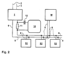
- the invention relates to an actuator sensor interface system with at least two Slaves, a master, an actuator sensor interface bus, AS-i bus, and one Power supply unit that supplies the slaves with power via the AS-i bus is capable of supplying, with each slave having a binary address and through Modulation of such a sequence of transmission pulses on the AS-i bus, which corresponds to the binary address of the slave, can be called up and to deliver a Response signal can be initiated, which consists of a by the called slave there is a sequence of response pulses modulated onto the AS-i bus, according to the preamble of claim 1 and a method for operating a such actuator sensor interface system according to the preamble of Claim.
- An AS-Interface or actuator sensor interface is a simple bus system for the networking of binary sensors and actuators.
- the actuator sensor interface system is used to connect sensors or actuators to one Host computer which e.g. a programmable logic controller or a PC or can be another bus computer.
- An actuator sensor interface system comprises a master and at least one slave; there are usually several Slaves available. The slaves are used to connect the sensors or Actuators to the actuator sensor interface system.
- the master and the slaves are each connected to a common AS-i bus and generally connected in parallel to each other, which bus in the Usually consists of only two lines.
- AS-i bus In the Usually consists of only two lines.
- Extenders or repeaters in the AS-i bus can typically allow over 100m interposed.
- the sensors or actuators are thus over the Slaves, the AS-i bus and the master connected to the host computer.
- the master establishes the data connection of the actuator sensor interface system to the host computer.
- the mostly binary sensors / actuators connected, whereby the master responds to the Bus system signals given by the slaves in a predetermined time grid, the AS-i master program made available to the host computer.
- binary sensors are used in actuator-sensor interface systems or actuators used.
- Each slave has a binary address.
- the master is calling e.g. All slaves with their addresses on and in successive cyclic order exchanges data telegrams with them. Usually within each cycle Exactly one data telegram is exchanged with each slave; the The total cycle time is typically a few milliseconds.
- the master modulates a specific one, the binary one Address of the slave corresponding sequence of transmission pulses on the AS-i bus.
- the so called, i.e. addressed slave becomes by the call Issues a response signal, which consists of a by the called slave on the AS-i bus modulated sequence of response pulses exists, which can be read by the master.
- the master To the response impulses To be able to receive undisturbed, the master usually pauses transmission of a certain duration before calling the next slave.
- the individual send and reply pulses have a duration of typically about 3 microseconds.
- AS-i bus serves both to supply power to the master and the slaves as well as for data transmission between them.
- AS-Interface A A special feature of AS-Interface is the voltage or power supply and data transmission over the same two lines.
- a power supply unit is used for the master and the slaves, e.g. a power supply.
- the simultaneous power supply and data transmission requires one Data decoupling between the voltage or current source and the rest AS-Interface participants.
- the output of the power supply is usually over one Data decoupling also connected to the AS-i bus.
- the data decoupling is used to supply the slaves and the master DC voltage from the transmission and response pulses modulated onto the AS-i bus decouple.
- the data decoupling is essentially a low pass, which allows the DC voltage from the power supply to pass into the AS-i bus However, send and reply pulses from the AS-i bus via the power supply unit drains off.
- the data decoupling is usually part of a special AS-Interface Power supply. There are also AS-Interface masters with a low degree of protection with integrated data decoupling.
- the line length for AS interfaces is due to the data transmission and due to Reflections limited to 100m. You can also use two extenders or two repeaters the line length can be extended to a maximum of 300m.
- the invention is therefore based on the object of an actuator-sensor interface system and to provide a method for operating one which the Detection of multiple addressing of slaves and identification of the affected slaves clearly and independently of the installed topology of the Enable actuator sensor interface system.
- the task is the beginning of an actuator sensor interface system mentioned type solved according to the invention by a monitoring device, which is able to record the response impulses and when superimposed the response signals of at least two slaves trigger a switching or warning signal, so that the same is triggered if at least two slaves have the same binary Own address, these slaves by a sequence of transmission pulses simultaneously have been prompted to deliver their response signal and this Overlay response signals.
- an actuator sensor interface system comprising at least two slaves, one master, one Actuator sensor interface bus, AS-i bus, to which the slaves and the master are connected, as well as a power supply unit, which the slaves via is able to power the AS-i bus, with each slave being a binary one Has address and by modulating such a sequence of transmission pulses on the AS-i bus, which corresponds to the binary address of the slave, can be called up and prompted to emit a response signal which consists of a sequence of modulated on the AS-i bus by the called slave Response pulses exist, according to the invention, in that the response pulses can be detected by a monitoring device which, when superimposed the response signals of at least two slaves are a switching or warning signal triggers so that the same is triggered if at least two slaves are the same possess a binary address, these slaves through a sequence of transmission pulses are simultaneously prompted to issue one response signal each and this Overlay response signals.
- the invention thus allows a functional expansion of a bus system Control of networked and communicating slaves.
- she describes a way to uniquely identify multiple addresses of slaves in actuator sensor interface systems, without in the topology of the AS interface Need to intervene.
- the voltage source can be in Leave the lower degree of protection, for example in IP20, and still AS-Interface in high degree of protection can be used. Even voltage sources with a high degree of protection, for example in IP65, can be used.
- the switch or Warning signal thus indicates according to the invention that two or more slaves have the same binary address.
- the actuator sensor interface system able to cycle so many different ones To modulate sequences of transmission pulses on the AS-i bus, like the actuator sensor interface system Slaves, and between two series of Transmit impulses to maintain a pause in which no modulation of Transmitting pulses on the AS-i bus.
- each sequence of transmission pulses of a binary address of exactly one slave i.e. all slaves are called up one after the other in cyclical order and are assigned to Issued a sequence of response pulses.
- the generation of the Transmitting impulses need not necessarily be made by the master; rather can a dedicated addressing device, e.g. temporarily for control purposes connected to the AS-i bus.
- the broadcast breaks serve to ensure undisturbed reception of the response signals enable.
- two or more slaves erroneously use the same binary Own address their response signals are superimposed, which according to the invention is detected and leads to the triggering of the switching or warning signal.
- transmission current which In principle, the transmission current is a current increase from that of the power supply unit current or the current flowing in the AS-i bus.
- the monitoring device is therefore capable of superimposing two response signals on it to recognize that the amplitude of the fluctuations of the power supply unit current or the current flowing in the AS-i bus Current exceeds a predetermined threshold.
- the threshold value is preferably greater than the maximum amplitude of the fluctuations with which those from the power supply unit current or the current flowing in the AS-i bus is affected and which are caused by a slave sending a response signal, m.a.W. the threshold is greater than the simple transmission current of a slave. The However, the threshold is less than twice this amplitude, m.W. the Threshold value is less than twice the transmission current of a slave.
- the threshold value can be greater than 1.1 times the maximum Amplitude of those fluctuations with which those from the power supply unit current or the current flowing in the AS-i bus is affected and which are caused by a slave receiving a response signal emits, and can be less than 1.9 times this amplitude.
- the threshold is chosen so that when a single slave is a Response signal, the threshold is not exceeded, but then, if the response signals of two or more slaves overlap, the Threshold is exceeded.
- the transmission pulses detected by means of a transmission signal decoder which in each sequence of Transmit pulses that correspond to a binary address of a slave, this Is able to recognize the address.
- the actuator sensor interface system therefore a transmission signal decoding device which contains the transmission pulses is able to record and in each sequence of transmission pulses which corresponds to a binary address of a slave to recognize this address capable, i.e. read the sent addresses.
- the switching or warning signal can be detected and at Ascertaining the last recognized address of a slave is displayed and / or saved. In this way, it is immediately possible that one Address which incorrectly calls two or more slaves at the same time, to read or to find out.
- the transmission signal decoder be able to detect the switching or warning signal and if the same is found, display the last recognized address of a slave and / or save.
- the one emitted by the power supply unit or the one flowing in the AS-i bus Current strength can be measured in different ways. In principle are too all methods of current measurement can be used for this purpose.
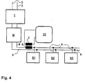
- the on a between the power supply unit and a cable of the AS-i bus or a resistor interposed in the AS-i bus tapped voltage drop, fed to the monitoring device and as a measure of the power unit's output the current flowing in the AS-i bus are used, whereby either this voltage drop the amount of the power supply unit current or the amount of current flowing in the AS-i bus is determined, or from the fluctuations of this voltage drop Amplitude of the fluctuations in the output from the power supply unit Current or the amplitude of the fluctuations in the AS-i bus flowing current is determined.
- the actuator sensor interface system can have a resistor have, which between the power supply unit and a line of AS-i bus or in the AS-i bus is interposed, so that the on the Resistance voltage drop is a measure of that from the power supply unit current or for the current flowing in the AS-i bus, wherein the monitoring device either this voltage drop record and from this the amount of the power supply unit Current or the amount of current flowing in the AS-i bus is able to determine, or the fluctuations of this voltage drop to capture and from this the amplitude of the fluctuations of the power supply unit emitted current strength or the amplitude of the Fluctuations in the current flowing in the AS-i bus is able to determine.
- the constant portion of the voltage tapped at the resistor can of course be blocked by a capacitor.
- a transformer with a first and a second Winding are used, the first winding between the Power supply unit and one line of the AS-i bus or in one line of the AS-i bus is interposed, and the fluctuations of the second winding output voltage as a measure of the fluctuations of the current output by the power supply unit or for the Fluctuations in the current flowing in the AS-i bus are used and from the temporal behavior of those emitted by the second winding Voltage the amplitude of the fluctuations of the power supply unit emitted current is determined or the amplitude of the Fluctuations in the current flowing in the AS-i bus is determined.
- An actuator-sensor interface system can be used for this purpose have a transformer with a first and a second winding, wherein the first winding between the power supply unit and a line of the AS-i bus or in a line of the AS-i bus, so that the fluctuations in the voltage output by the second winding Measure of the fluctuations in the output from the power supply unit Current or for the fluctuations in the current flowing in the AS-i bus and the monitoring device are those of the second winding recorded voltage and from their temporal behavior the Amplitude of fluctuations from the power supply unit current or the amplitude of the fluctuations in the AS-i bus flowing current is able to determine.
- the advantage here is that from the outset by the time-variable portion of the current delivered by the power supply unit or in the AS-i bus flowing current reaches the monitoring device during the Time-constant proportion of the current without influencing the invention Detection of the superposition of two response signals remains. That way not only improves the relative accuracy of detection, but it will also the influence of a possible slow, e.g. temperature-related drift of the constant portion of the electricity avoided.
- the occurrence of response pulses is recorded during each pause and, if there is no such transmission within a pause, the last recognized address of a slave is displayed and / or saved.
- the transmit signal decoder be able to do so during each transmit pause to detect the occurrence of response impulses and, if so, within there is no transmission pause, the last recognized address of a slave display and / or save.
- An error signal can also be triggered, if within a transmission pause There are no response impulses.
- the transmission signal decoding device be set up so that in the event that within a pause There are no response impulses to trigger an error signal.
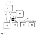
- the power supply unit can be a power source and a data decoupling comprise, wherein the data decoupling between the power source and the AS-i bus is interposed.
- the power supply unit and the monitoring device can be arranged in a common housing.
- the transmission signal decoding device and the monitoring device be arranged in a common housing.
- a current measurement via a shunt to be inserted in the AS-Interface cable leads to undesirable DC voltage drops in the worst-case scenario (DC current to currently 8A possible) and large power losses to be dimensioned accordingly of the shunt.
- DC current to currently 8A possible DC current to currently 8A possible
- large power losses to be dimensioned accordingly of the shunt for the detection of double addressing is only the AC transmission current of the AS-Interface slaves is relevant and not the DC current consumption of all connected participants and consumers, sensors, actuators.
- the data decoupling can be done by the possibility of a current measurement and a additional logical evaluation, which are separate from the Voltage source, either with high protection or low protection, can be executed.
- the data decoupling is expanded by the possibility the current measurement and an additional logical evaluation according to the invention in its own housing, together with the AS-Interface Master, together with an AS-Interface power supply, together with a AS-Interface Repeater), together with an AS-Interface Extender or can be used together with an AS-Interface earth fault monitor.
- the method thus enables the device to take advantage of AS-Interface as low costs per AS-Interface slave with a high degree of protection, with simple wiring with a high degree of protection, the invention being the detection enables multiple addressing of AS-Interface slaves.
- the data decoupling is made possible by the possibility of a current measurement and an additional logical evaluation of the information on the AS-Interface expanded and constructed separately from the voltage source with a high degree of protection, which means that Voltage source also in a simple protection class, spatially separated from the Data decoupling with a high degree of protection can be constructed more simply.
- the data decoupling including the current measurement and Logical evaluation can also be carried out together with an AS-Interface power supply high degree of protection must be set up separately from the voltage source.
- Two data decouplings including the current measurement and logical evaluation together with an AS-Interface Repeater in high Protection class must be set up separately from the voltage source.
- the Data decoupling including the current measurement and logical evaluation together with an AS-Interface extender with a high degree of protection separated from the Voltage source can be built. It is also possible that the data decoupling including the current measurement and logical evaluation together with an AS-Interface earth fault monitor with a high degree of protection from the voltage source can be separated.
- the data decoupling including the current measurement and the logical evaluation can be spatially separated from the voltage source be built up, creating an insensitive DC voltage over a longer period Transfer distance between the voltage source and the data decoupling and after the data decoupling the one specified at AS-Interface maximum cable length is available.
- the data decoupling including the Current measurement and logical evaluation can also be spatially separated from the voltage source built or integrated in an AS-Interface master causing an insensitive DC voltage over a longer distance is transmitted between the voltage source and the data decoupling and after the data decoupling the maximum specified at AS-Interface Cable length is available.
- the object of the invention serves in particular the unambiguous ability to diagnose multiple addressing due to incorrect addressing of AS-Interface Slaves during commissioning, maintenance and repair for bus systems the AS-Interface standard for controlling and activating each other networked and communicating binary, multiple modules, AS-Interface Slaves, whereby in particular the downtimes of the systems during Maintenance and repair drastically shortened and thus the availability of the Overall system is significantly increased.
- the data decoupling is extended by the Possibility of current measurement and an additional logical evaluation separated from the voltage source with a high degree of protection, which makes the Voltage source with a simple protection class, spatially separated from the data decoupling can be constructed more simply in low or high protection class and the Power loss can be delivered more easily.
Landscapes
- Physics & Mathematics (AREA)
- General Physics & Mathematics (AREA)
- Engineering & Computer Science (AREA)
- Automation & Control Theory (AREA)
- Arrangements For Transmission Of Measured Signals (AREA)
- Small-Scale Networks (AREA)
- Control Of Electric Motors In General (AREA)
- Air Bags (AREA)
- Vehicle Body Suspensions (AREA)
Applications Claiming Priority (2)
| Application Number | Priority Date | Filing Date | Title |
|---|---|---|---|
| DE10156148 | 2001-11-15 | ||
| DE10156148 | 2001-11-15 |
Publications (3)
| Publication Number | Publication Date |
|---|---|
| EP1312991A2 true EP1312991A2 (fr) | 2003-05-21 |
| EP1312991A3 EP1312991A3 (fr) | 2005-11-30 |
| EP1312991B1 EP1312991B1 (fr) | 2007-03-07 |
Family
ID=7705864
Family Applications (1)
| Application Number | Title | Priority Date | Filing Date |
|---|---|---|---|
| EP02025463A Expired - Lifetime EP1312991B1 (fr) | 2001-11-15 | 2002-11-15 | Système d'interface actionneur capteur et procédé pour le commander |
Country Status (3)
| Country | Link |
|---|---|
| EP (1) | EP1312991B1 (fr) |
| AT (1) | ATE356376T1 (fr) |
| DE (2) | DE50209644D1 (fr) |
Cited By (9)
| Publication number | Priority date | Publication date | Assignee | Title |
|---|---|---|---|---|
| US7319921B2 (en) * | 2002-05-22 | 2008-01-15 | Underwood Fred R | Water treatment control system |
| EP1898287A1 (fr) * | 2006-09-05 | 2008-03-12 | Siemens Aktiengesellschaft | Réseau ASI pour des environnements en danger d'explosion |
| EP2254011A1 (fr) * | 2009-05-20 | 2010-11-24 | Siemens Aktiengesellschaft | Alimentation en énergie d'une interface AS |
| EP2348374A1 (fr) * | 2010-01-18 | 2011-07-27 | Siemens Aktiengesellschaft | Procédé de détection d'un adressage multiple défectueux d'un réseau fonctionnant selon le principe maître-esclave et un réseau à interface de capteur d'actionneur correspondant |
| DE102013216564A1 (de) | 2013-08-21 | 2015-02-26 | Ifm Electronic Gmbh | Verfahren zur Erkennung einer Doppeladressierung von Slaves in einem Master-Slave-Bussystem |
| WO2017211895A1 (fr) * | 2016-06-09 | 2017-12-14 | Beckhoff Automation Gmbh | Module de bus de terrain et procédé de fonctionnement d'un système de bus de terrain |
| CN110579989A (zh) * | 2019-09-12 | 2019-12-17 | 武汉介观生物科技有限责任公司 | 一种支持通用传感和执行器的双系统程控设备 |
| US10967303B2 (en) | 2018-03-08 | 2021-04-06 | Mark W. Romers | Filter backwash control system for a water or wastewater treatment system to conserve water during the filter backwash process |
| CN115427697A (zh) * | 2020-04-28 | 2022-12-02 | 圣达有限公司 | 用于控制磁浮系统的控制系统 |
Families Citing this family (10)
| Publication number | Priority date | Publication date | Assignee | Title |
|---|---|---|---|---|
| DE102007025852B3 (de) | 2007-06-01 | 2009-01-02 | I F M Electronic Gmbh | Überwachungseinrichtung zur Erkennung einer fehlerhaften Adressierung eines Aktuator-Sensor-Interface-Slaves |
| DE102009033229B4 (de) | 2009-07-14 | 2018-07-12 | Bihl+Wiedemann Gmbh | Verfahren zur Erkennung von Doppeladressierungen in AS Interface Netzen |
| DE102011080550B4 (de) * | 2010-08-05 | 2019-02-07 | Ifm Electronic Gmbh | Mastereinheit mit Erweiterungsmodul für ein Bussystem der Automatisierungstechnik |
| DE102011101172A1 (de) | 2011-05-11 | 2012-11-15 | Andreas Schiff | Mehrfachadresserkennung in AS-Interface-Netzwerken |
| WO2013013710A1 (fr) | 2011-07-27 | 2013-01-31 | Siemens Aktiengesellschaft | Détection d'un adressage multiple défectueux à l'intérieur d'un système d'interface actionneur-capteur |
| DE102012202424A1 (de) * | 2012-02-16 | 2013-08-22 | Ifm Electronic Gmbh | Erdschlusswächter für ein ASi-Sensor-Aktor-Netzwerk |
| DE102014117590A1 (de) * | 2014-12-01 | 2016-06-02 | Logicdata Electronic & Software Entwicklungs Gmbh | Elektrisch verstellbares Tischsystem und Verfahren zur Herstellung eines elektrisch verstellbaren Tischsystems |
| DE102016221139B4 (de) * | 2016-10-26 | 2018-12-13 | SPX Flow Technology Rosista GmbH | AS-i Netzwerk und Betriebsverfahren |
| DE102017128249B4 (de) | 2017-11-29 | 2022-02-17 | Ifm Electronic Gmbh | Anordnung für einen Aktuator-Sensor Interface Feldbus (AS-i-Bus) mit einem Diagnosegerät |
| DE102022126354B3 (de) | 2022-10-11 | 2023-12-21 | Ifm Electronic Gmbh | Verfahren zur automatischen Adressvergabe in einem AS-I-Master-Slave-Bussystem |
Family Cites Families (3)
| Publication number | Priority date | Publication date | Assignee | Title |
|---|---|---|---|---|
| FR2664715B1 (fr) * | 1990-07-13 | 1994-01-21 | Moulinex | Procede d'attribution d'adresses dans un reseau domotique. |
| DE9416127U1 (de) * | 1994-10-06 | 1994-12-08 | Siemens AG, 80333 München | Modul für ein Aktuator-Sensor-Interface-System |
| DE19947501C5 (de) * | 1999-10-01 | 2016-06-30 | Ifm Electronic Gmbh | Aktuator-Sensor-Interface-Slave |
-
2002
- 2002-11-15 DE DE50209644T patent/DE50209644D1/de not_active Expired - Lifetime
- 2002-11-15 AT AT02025463T patent/ATE356376T1/de not_active IP Right Cessation
- 2002-11-15 EP EP02025463A patent/EP1312991B1/fr not_active Expired - Lifetime
- 2002-11-15 DE DE10253566A patent/DE10253566A1/de not_active Withdrawn
Cited By (13)
| Publication number | Priority date | Publication date | Assignee | Title |
|---|---|---|---|---|
| US7319921B2 (en) * | 2002-05-22 | 2008-01-15 | Underwood Fred R | Water treatment control system |
| EP1898287A1 (fr) * | 2006-09-05 | 2008-03-12 | Siemens Aktiengesellschaft | Réseau ASI pour des environnements en danger d'explosion |
| WO2008028793A1 (fr) * | 2006-09-05 | 2008-03-13 | Siemens Aktiengesellschaft | Réseau asi pour des zones a risques d'explosion |
| EP2254011A1 (fr) * | 2009-05-20 | 2010-11-24 | Siemens Aktiengesellschaft | Alimentation en énergie d'une interface AS |
| EP2348374A1 (fr) * | 2010-01-18 | 2011-07-27 | Siemens Aktiengesellschaft | Procédé de détection d'un adressage multiple défectueux d'un réseau fonctionnant selon le principe maître-esclave et un réseau à interface de capteur d'actionneur correspondant |
| DE102013216564A1 (de) | 2013-08-21 | 2015-02-26 | Ifm Electronic Gmbh | Verfahren zur Erkennung einer Doppeladressierung von Slaves in einem Master-Slave-Bussystem |
| WO2017211895A1 (fr) * | 2016-06-09 | 2017-12-14 | Beckhoff Automation Gmbh | Module de bus de terrain et procédé de fonctionnement d'un système de bus de terrain |
| US10567191B2 (en) | 2016-06-09 | 2020-02-18 | Beckhoff Automation Gmbh | Fieldbus module and method for operating a fieldbus system |
| US11229862B2 (en) | 2017-03-08 | 2022-01-25 | Mark W. Romers | Filter backwash control system for a water or wastewater treatment system to conserve water during the filter backwash process |
| US11247148B2 (en) | 2017-03-08 | 2022-02-15 | Mark W. Romers | Filter backwash control system for a water or wastewater treatment system to conserve water during the filter backwash process |
| US10967303B2 (en) | 2018-03-08 | 2021-04-06 | Mark W. Romers | Filter backwash control system for a water or wastewater treatment system to conserve water during the filter backwash process |
| CN110579989A (zh) * | 2019-09-12 | 2019-12-17 | 武汉介观生物科技有限责任公司 | 一种支持通用传感和执行器的双系统程控设备 |
| CN115427697A (zh) * | 2020-04-28 | 2022-12-02 | 圣达有限公司 | 用于控制磁浮系统的控制系统 |
Also Published As
| Publication number | Publication date |
|---|---|
| EP1312991B1 (fr) | 2007-03-07 |
| ATE356376T1 (de) | 2007-03-15 |
| EP1312991A3 (fr) | 2005-11-30 |
| DE50209644D1 (de) | 2007-04-19 |
| DE10253566A1 (de) | 2003-05-28 |
Similar Documents
| Publication | Publication Date | Title |
|---|---|---|
| EP1312991B1 (fr) | Système d'interface actionneur capteur et procédé pour le commander | |
| DE10392421B4 (de) | Handdiagnose- und kommunikationsgerät mit automatischer Buserkennung | |
| EP2000866B1 (fr) | Dispositif de surveillance destiné à la reconnaissance d'un adressage incorrect d'un esclave dans un système de bus de terrain | |
| EP2359539B1 (fr) | Protocole de transmission de données | |
| DE102016110641B3 (de) | Feldbusmodul und Verfahren zum Betreiben eines Feldbussystems | |
| EP2008352B1 (fr) | Procédé de contrôle de la qualité de l'énergie électrique dans un réseau d'alimentation en énergie électrique, appareil de terrain de contrôle de la qualité de courant et système de contrôle de la qualité de courant | |
| EP1979790B1 (fr) | Procédé et dispositif d'attribution d'adresses dans un système comportant plusieurs unités de générateur disposées de façon parallèle | |
| EP2745081B1 (fr) | Module capteur pour la détection d'un paramètre de fonctionnement, procédé de surveillance d'un module capteur | |
| WO2005053221A2 (fr) | Reseau, notamment reseau pa profibus, a proprietes de redondance, element de ramification pour appareil d'abonne dans un reseau de ce type, gestionnaire de redondance pour un reseau de ce type et procede pour faire fonctionner un reseau de ce type | |
| EP2917795A1 (fr) | Procédé d'identification de la position de montage relative des modules utilisés dans un système électronique modulaire | |
| DE69213505T2 (de) | Mehrfachadapter mit einer Schaltung zur Antwortssignaldetektion | |
| EP1979793B1 (fr) | Procédé et dispositif d'attribution d'adresses dans un système comportant plusieurs unités de générateur disposées de façon parallèle | |
| DE4017533C2 (fr) | ||
| DE102013216564B4 (de) | Verfahren zur Erkennung einer Doppeladressierung von Slaves in einem Master-Slave-Bussystem | |
| DE102018118873A1 (de) | Elektronisches Schaltgerät für die Automatisierungstechnik und optischer Empfänger | |
| DE102019103223B4 (de) | Vorrichtung und Verfahren zur Signalisierung eines Datenbusausfalls durch eine Ultraschallmessvorrichtung | |
| EP3387789A1 (fr) | Système de bus comprenant un premier ensemble d'abonnés et procédé pour faire fonctionner un système de bus | |
| DE4336698C2 (de) | Servoregler | |
| EP2348374B1 (fr) | Procédé de détection d'un adressage multiple défectueux d'un réseau fonctionnant selon le principe maître-esclave et un réseau à interface de capteur d'actionneur correspondant | |
| DE102012111018A1 (de) | Mehrkanaliges Messdatenerfassungsgerät | |
| DE102009016972B4 (de) | Kommunikationssystem zum dezentralen und autarken Überwachen und Steuern eines unterlagerten Bussystems | |
| DE102009033229A1 (de) | Verfahren zur Erkennung von Doppeladressierungen in AS Interface Netzen | |
| DE2309611B2 (de) | Verfahren zur Fernübertragung und Anzeige von elektrischen Meßwerten bei Elektrolysezellen | |
| DE3030252C2 (de) | Verfahren und Schaltungsanordnung zur Erfassung der Schaltzustände einer Vielzahl von peripheren Schaltern | |
| EP2418551B1 (fr) | Procédé de diagnostic pour un système de bus de terrain exécuté selon la norme d'interface AS |
Legal Events
| Date | Code | Title | Description |
|---|---|---|---|
| PUAI | Public reference made under article 153(3) epc to a published international application that has entered the european phase |
Free format text: ORIGINAL CODE: 0009012 |
|
| AK | Designated contracting states |
Designated state(s): AT BE BG CH CY CZ DE DK EE ES FI FR GB GR IE IT LI LU MC NL PT SE SK TR |
|
| AX | Request for extension of the european patent |
Extension state: AL LT LV MK RO SI |
|
| PUAL | Search report despatched |
Free format text: ORIGINAL CODE: 0009013 |
|
| AK | Designated contracting states |
Kind code of ref document: A3 Designated state(s): AT BE BG CH CY CZ DE DK EE ES FI FR GB GR IE IT LI LU MC NL PT SE SK TR |
|
| AX | Request for extension of the european patent |
Extension state: AL LT LV MK RO SI |
|
| 17P | Request for examination filed |
Effective date: 20051109 |
|
| AKX | Designation fees paid |
Designated state(s): AT BE BG CH CY CZ DE DK EE ES FI FR GB GR IE IT LI LU MC NL PT SE SK TR |
|
| GRAP | Despatch of communication of intention to grant a patent |
Free format text: ORIGINAL CODE: EPIDOSNIGR1 |
|
| GRAS | Grant fee paid |
Free format text: ORIGINAL CODE: EPIDOSNIGR3 |
|
| GRAA | (expected) grant |
Free format text: ORIGINAL CODE: 0009210 |
|
| AK | Designated contracting states |
Kind code of ref document: B1 Designated state(s): AT BE BG CH CY CZ DE DK EE ES FI FR GB GR IE IT LI LU MC NL PT SE SK TR |
|
| PG25 | Lapsed in a contracting state [announced via postgrant information from national office to epo] |
Ref country code: IE Free format text: LAPSE BECAUSE OF FAILURE TO SUBMIT A TRANSLATION OF THE DESCRIPTION OR TO PAY THE FEE WITHIN THE PRESCRIBED TIME-LIMIT Effective date: 20070307 Ref country code: FI Free format text: LAPSE BECAUSE OF FAILURE TO SUBMIT A TRANSLATION OF THE DESCRIPTION OR TO PAY THE FEE WITHIN THE PRESCRIBED TIME-LIMIT Effective date: 20070307 Ref country code: NL Free format text: LAPSE BECAUSE OF FAILURE TO SUBMIT A TRANSLATION OF THE DESCRIPTION OR TO PAY THE FEE WITHIN THE PRESCRIBED TIME-LIMIT Effective date: 20070307 |
|
| REG | Reference to a national code |
Ref country code: GB Ref legal event code: FG4D Free format text: NOT ENGLISH |
|
| REG | Reference to a national code |
Ref country code: CH Ref legal event code: EP |
|
| REF | Corresponds to: |
Ref document number: 50209644 Country of ref document: DE Date of ref document: 20070419 Kind code of ref document: P |
|
| REG | Reference to a national code |
Ref country code: IE Ref legal event code: FG4D Free format text: LANGUAGE OF EP DOCUMENT: GERMAN |
|
| PG25 | Lapsed in a contracting state [announced via postgrant information from national office to epo] |
Ref country code: SE Free format text: LAPSE BECAUSE OF FAILURE TO SUBMIT A TRANSLATION OF THE DESCRIPTION OR TO PAY THE FEE WITHIN THE PRESCRIBED TIME-LIMIT Effective date: 20070607 |
|
| PG25 | Lapsed in a contracting state [announced via postgrant information from national office to epo] |
Ref country code: ES Free format text: LAPSE BECAUSE OF FAILURE TO SUBMIT A TRANSLATION OF THE DESCRIPTION OR TO PAY THE FEE WITHIN THE PRESCRIBED TIME-LIMIT Effective date: 20070618 |
|
| PG25 | Lapsed in a contracting state [announced via postgrant information from national office to epo] |
Ref country code: PT Free format text: LAPSE BECAUSE OF FAILURE TO SUBMIT A TRANSLATION OF THE DESCRIPTION OR TO PAY THE FEE WITHIN THE PRESCRIBED TIME-LIMIT Effective date: 20070807 |
|
| NLV1 | Nl: lapsed or annulled due to failure to fulfill the requirements of art. 29p and 29m of the patents act | ||
| GBV | Gb: ep patent (uk) treated as always having been void in accordance with gb section 77(7)/1977 [no translation filed] |
Effective date: 20070307 |
|
| REG | Reference to a national code |
Ref country code: IE Ref legal event code: FD4D |
|
| EN | Fr: translation not filed | ||
| PG25 | Lapsed in a contracting state [announced via postgrant information from national office to epo] |
Ref country code: GB Free format text: LAPSE BECAUSE OF FAILURE TO SUBMIT A TRANSLATION OF THE DESCRIPTION OR TO PAY THE FEE WITHIN THE PRESCRIBED TIME-LIMIT Effective date: 20070307 Ref country code: SK Free format text: LAPSE BECAUSE OF FAILURE TO SUBMIT A TRANSLATION OF THE DESCRIPTION OR TO PAY THE FEE WITHIN THE PRESCRIBED TIME-LIMIT Effective date: 20070307 |
|
| PG25 | Lapsed in a contracting state [announced via postgrant information from national office to epo] |
Ref country code: CZ Free format text: LAPSE BECAUSE OF FAILURE TO SUBMIT A TRANSLATION OF THE DESCRIPTION OR TO PAY THE FEE WITHIN THE PRESCRIBED TIME-LIMIT Effective date: 20070307 |
|
| PLBE | No opposition filed within time limit |
Free format text: ORIGINAL CODE: 0009261 |
|
| STAA | Information on the status of an ep patent application or granted ep patent |
Free format text: STATUS: NO OPPOSITION FILED WITHIN TIME LIMIT |
|
| PG25 | Lapsed in a contracting state [announced via postgrant information from national office to epo] |
Ref country code: DK Free format text: LAPSE BECAUSE OF FAILURE TO SUBMIT A TRANSLATION OF THE DESCRIPTION OR TO PAY THE FEE WITHIN THE PRESCRIBED TIME-LIMIT Effective date: 20070307 |
|
| 26N | No opposition filed |
Effective date: 20071210 |
|
| PG25 | Lapsed in a contracting state [announced via postgrant information from national office to epo] |
Ref country code: IT Free format text: LAPSE BECAUSE OF FAILURE TO SUBMIT A TRANSLATION OF THE DESCRIPTION OR TO PAY THE FEE WITHIN THE PRESCRIBED TIME-LIMIT Effective date: 20070307 Ref country code: GR Free format text: LAPSE BECAUSE OF FAILURE TO SUBMIT A TRANSLATION OF THE DESCRIPTION OR TO PAY THE FEE WITHIN THE PRESCRIBED TIME-LIMIT Effective date: 20070608 Ref country code: FR Free format text: LAPSE BECAUSE OF FAILURE TO SUBMIT A TRANSLATION OF THE DESCRIPTION OR TO PAY THE FEE WITHIN THE PRESCRIBED TIME-LIMIT Effective date: 20071026 |
|
| BERE | Be: lapsed |
Owner name: BIHL + WIEDEMANN G.M.B.H. Effective date: 20071130 |
|
| PG25 | Lapsed in a contracting state [announced via postgrant information from national office to epo] |
Ref country code: MC Free format text: LAPSE BECAUSE OF NON-PAYMENT OF DUE FEES Effective date: 20071130 |
|
| PG25 | Lapsed in a contracting state [announced via postgrant information from national office to epo] |
Ref country code: CH Free format text: LAPSE BECAUSE OF NON-PAYMENT OF DUE FEES Effective date: 20071130 Ref country code: LI Free format text: LAPSE BECAUSE OF NON-PAYMENT OF DUE FEES Effective date: 20071130 |
|
| REG | Reference to a national code |
Ref country code: CH Ref legal event code: PL |
|
| PG25 | Lapsed in a contracting state [announced via postgrant information from national office to epo] |
Ref country code: BE Free format text: LAPSE BECAUSE OF NON-PAYMENT OF DUE FEES Effective date: 20071130 |
|
| PG25 | Lapsed in a contracting state [announced via postgrant information from national office to epo] |
Ref country code: FR Free format text: LAPSE BECAUSE OF FAILURE TO SUBMIT A TRANSLATION OF THE DESCRIPTION OR TO PAY THE FEE WITHIN THE PRESCRIBED TIME-LIMIT Effective date: 20070307 |
|
| PG25 | Lapsed in a contracting state [announced via postgrant information from national office to epo] |
Ref country code: EE Free format text: LAPSE BECAUSE OF FAILURE TO SUBMIT A TRANSLATION OF THE DESCRIPTION OR TO PAY THE FEE WITHIN THE PRESCRIBED TIME-LIMIT Effective date: 20070307 |
|
| PG25 | Lapsed in a contracting state [announced via postgrant information from national office to epo] |
Ref country code: AT Free format text: LAPSE BECAUSE OF NON-PAYMENT OF DUE FEES Effective date: 20071115 |
|
| PG25 | Lapsed in a contracting state [announced via postgrant information from national office to epo] |
Ref country code: CY Free format text: LAPSE BECAUSE OF FAILURE TO SUBMIT A TRANSLATION OF THE DESCRIPTION OR TO PAY THE FEE WITHIN THE PRESCRIBED TIME-LIMIT Effective date: 20070307 |
|
| PG25 | Lapsed in a contracting state [announced via postgrant information from national office to epo] |
Ref country code: LU Free format text: LAPSE BECAUSE OF NON-PAYMENT OF DUE FEES Effective date: 20071115 Ref country code: BG Free format text: LAPSE BECAUSE OF FAILURE TO SUBMIT A TRANSLATION OF THE DESCRIPTION OR TO PAY THE FEE WITHIN THE PRESCRIBED TIME-LIMIT Effective date: 20070607 |
|
| PG25 | Lapsed in a contracting state [announced via postgrant information from national office to epo] |
Ref country code: TR Free format text: LAPSE BECAUSE OF FAILURE TO SUBMIT A TRANSLATION OF THE DESCRIPTION OR TO PAY THE FEE WITHIN THE PRESCRIBED TIME-LIMIT Effective date: 20070307 |
|
| PGFP | Annual fee paid to national office [announced via postgrant information from national office to epo] |
Ref country code: DE Payment date: 20211130 Year of fee payment: 20 |
|
| REG | Reference to a national code |
Ref country code: DE Ref legal event code: R071 Ref document number: 50209644 Country of ref document: DE |