EP1312991B1 - Système d'interface actionneur capteur et procédé pour le commander - Google Patents
Système d'interface actionneur capteur et procédé pour le commander Download PDFInfo
- Publication number
- EP1312991B1 EP1312991B1 EP02025463A EP02025463A EP1312991B1 EP 1312991 B1 EP1312991 B1 EP 1312991B1 EP 02025463 A EP02025463 A EP 02025463A EP 02025463 A EP02025463 A EP 02025463A EP 1312991 B1 EP1312991 B1 EP 1312991B1
- Authority
- EP
- European Patent Office
- Prior art keywords
- bus
- power supply
- slaves
- supply unit
- fluctuations
- Prior art date
- Legal status (The legal status is an assumption and is not a legal conclusion. Google has not performed a legal analysis and makes no representation as to the accuracy of the status listed.)
- Expired - Lifetime
Links
Images

Classifications
-
- G—PHYSICS
- G05—CONTROLLING; REGULATING
- G05B—CONTROL OR REGULATING SYSTEMS IN GENERAL; FUNCTIONAL ELEMENTS OF SUCH SYSTEMS; MONITORING OR TESTING ARRANGEMENTS FOR SUCH SYSTEMS OR ELEMENTS
- G05B19/00—Program-control systems
- G05B19/02—Program-control systems electric
- G05B19/04—Program control other than numerical control, i.e. in sequence controllers or logic controllers
- G05B19/042—Program control other than numerical control, i.e. in sequence controllers or logic controllers using digital processors
- G05B19/0423—Input/output
-
- G—PHYSICS
- G05—CONTROLLING; REGULATING
- G05B—CONTROL OR REGULATING SYSTEMS IN GENERAL; FUNCTIONAL ELEMENTS OF SUCH SYSTEMS; MONITORING OR TESTING ARRANGEMENTS FOR SUCH SYSTEMS OR ELEMENTS
- G05B2219/00—Program-control systems
- G05B2219/20—Pc systems
- G05B2219/25—Pc structure of the system
- G05B2219/25017—ASI actuator sensor interface, bus, network
-
- G—PHYSICS
- G05—CONTROLLING; REGULATING
- G05B—CONTROL OR REGULATING SYSTEMS IN GENERAL; FUNCTIONAL ELEMENTS OF SUCH SYSTEMS; MONITORING OR TESTING ARRANGEMENTS FOR SUCH SYSTEMS OR ELEMENTS
- G05B2219/00—Program-control systems
- G05B2219/20—Pc systems
- G05B2219/25—Pc structure of the system
- G05B2219/25132—Superposition data signals on power lines for actuators
Definitions
- the invention relates to an actuator-sensor interface system with at least two slaves, a master, an actuator-sensor interface bus, AS-i bus, and a power supply unit, which power the slaves via the AS-i bus each slave has a binary address and by modulating such a sequence of transmit pulses on the AS-i bus, which corresponds to the binary address of the slave, callable and the triggering of a response signal veranpipingbar, which is one of the according to the preamble of claim 1 and a method for operating such an actuator-sensor-interface system according to the preamble of the claim.
- An AS-Interface or Actuator Sensor Interface is a simple bus system for networking binary sensors and actuators.
- the actuator-sensor-interface system is used for coupling sensors or actuators to a host computer, which, for example, a programmable logic controller or a PC or another bus computer may be.
- An actuator-sensor interface system comprises a master and at least one slave; As a rule, several slaves are available. The slaves are used to connect the sensors or actuators to the actuator-sensor-interface system.
- the master and the slaves are each connected to a common AS-i bus and in this case generally parallel to each other, which bus usually consists of only two lines. In order to allow long line lengths of typically over 100m, extenders or repeaters may be interposed in the AS-i bus.
- the sensors or actuators are thus connected to the host computer via the slaves, the AS-i bus and the master.
- the master establishes the data connection of the actuator-sensor-interface system to the host computer.
- the mostly binary sensors / actuators are connected to the host computer via the AS-i master, with the master providing the signals sent by the slaves to the bus system in a predefined time frame, the AS-i master program, to the host computer.
- binary sensors or actuators are used in actuator-sensor interface systems.
- Each slave has a binary address.
- the master calls e.g. in cyclic order one after the other all slaves with their address and exchanges data telegrams with them. Within each cycle, exactly one data telegram should normally be exchanged with each slave; the total cycle time is typically a few milliseconds.
- the master modulates a specific sequence of transmission pulses on the AS-i bus that corresponds to the binary address of the slave.
- the thus called, i. addressed slave is caused by the call for the delivery of a response signal, which consists of a modulated by the called slave on the AS-i bus sequence of response pulses that can be read by the master.
- the master In order to be able to receive the response pulses undisturbed, the master generally sets a transmission pause of a certain duration before calling the next slave.
- the individual transmission and response pulses have a duration of typically about 3 microseconds.
- AS-i bus is used both for powering the master and the slaves and for data transmission between them.
- AS-Interface is thus the voltage or power supply and the data transmission over the same two lines.
- a power supply unit e.g. a power supply.
- the simultaneous power supply and data transmission requires a data decoupling between the voltage or current source and the rest AS-Interface participants.
- the output of the power supply is usually also connected to the AS-i bus via data decoupling.
- Data decoupling serves to decouple the DC voltage used to supply the slaves and the master from the transmit and response pulses modulated on the AS-i bus.
- the data decoupling is essentially a low-pass filter, which allows the DC voltage from the power supply to pass through the AS-i bus, but does not allow the transmit and response pulses to flow out of the AS-i bus via the power supply.
- Data decoupling is usually part of a special AS-Interface power supply. There are also low-protection AS-Interface masters with integrated data decoupling.
- a standard power supply without data decoupling can supply the AS-Interface circuit with voltage via the data decoupling in the AS-Interface master.
- the cable length for AS interfaces is limited to 100m due to data transmission and reflections.
- the cable length can be extended to a maximum of 300m.
- WO 96/11441 discloses a module that can recognize multiple addressing of the slaves of an ASI system as the last step of preprogramming by connecting an adapter of a programming device to the integrated circuit which is easily separable from the bus line.
- the invention is therefore based on the object to provide an actuator-sensor interface system and a method for operating such, which the detection of a multiple addressing of slaves and an identification of the slaves concerned clearly and independently of the installed topology of the actuator. Enable sensor interface system.
- the object is achieved in an actuator sensor interface system of the type mentioned in the present invention by a monitoring device which is capable of detecting the response pulses and triggers a switching or warning signal when superimposing the response signals of at least two slaves, so that the same is triggered, if at least two slaves have the same binary address, these slaves have been caused by a sequence of transmission pulses simultaneously for the delivery of each of their response signal and superimpose these response signals.
- each slave has a binary address and by modulating such a sequence of transmission pulses on the AS-i bus, which the binary address of the Slaves corresponds to, callable and can be triggered to deliver a response signal, which consists of a modulated by the called slave on the AS-i bus sequence of response pulses, according to the invention achieved in that the response pulses are detected by a monitoring device which upon superposition of the response signals at least two slaves a switching or warning signal triggers, so that the same is triggered if at least two slaves di have the same binary address, these slaves are caused by a series of transmission pulses simultaneously to the delivery of each response signal and superimpose these response signals.
- the invention thus allows a functional extension of a bus system for controlling interconnected and communicating slaves. It describes a way of unambiguously detecting multiple addressing of slaves in actuator-sensor-interface systems without having to intervene in the topology of the AS-Interface network.
- the voltage source can be left in a low degree of protection, for example in IP20, and nevertheless AS-Interface with a high degree of protection can be used. Voltage sources designed in high degree of protection, for example in IP65, can also be used.
- the switch or Warning signal thus indicates according to the invention that two or more slaves have the same binary address.
- the actuator-sensor-interface system is capable of modulating in cyclic succession as many different sequences of transmission pulses on the AS-i bus as the actuator-sensor-interface system has slaves, and between each Two episodes of transmission pulses to comply with a transmission pause, in which no modulation of transmission pulses on the AS-i bus.
- so many different sequences of transmit pulses are modulated onto the AS-i bus in a cyclical sequence, as the actuator-sensor interface system has slaves, and there is a transmission pause between every two sequences of transmit pulses maintained in which no transmission pulses are modulated onto the AS-i bus.
- each sequence of transmission pulses corresponds to a binary address of exactly one slave, i. All slaves are called in sequence in a cyclic sequence and caused to deliver a sequence of response pulses.
- the generation of the transmission pulses does not necessarily have to be done by the master; rather, this can be done by means of a separate addressing device, which can be e.g. temporarily connected to the AS-i bus for control purposes.
- the transmission pauses serve to allow undisturbed reception of the response signals.
- two or more slaves mistakenly have the same binary address, their response signals superimpose, which is determined according to the invention and leads to the triggering of the switching or warning signal.
- the superposition of two or more response signals, transmission streams, which reveals that two or more slaves were called simultaneously and therefore have the same binary address can be recognized in various ways.
- the fact that the current delivered by the power supply unit or that flowing in the AS-i bus can advantageously be used for this purpose Changing current by modulating the response pulses on the AS-i bus; the current change triggered by a response pulse is typically up to 60 mA. If two response pulses, transmission currents, are superimposed, this current change typically increases to about twice this value.
- the fluctuations which the current delivered by the power supply unit or the current flowing in the AS-i bus is subjected to, can therefore be used advantageously for the purpose of detecting a superposition of the response signals of two or more slaves. Because when addressing an address of a slave this draws in response from the power supply unit corresponding to its response current, transmit current, which transmission current in principle has an increase in the output of the power supply unit current or the current flowing in the AS-i bus current result.
- the monitoring device is able to detect a superimposition of two response signals that the amplitude of the fluctuations of the current output by the power supply unit or the current flowing in the AS-i bus current exceeds a predetermined threshold.
- the threshold value is preferably greater than the maximum amplitude of those fluctuations with which the current output by the power supply unit or the current flowing in the AS-i bus is affected and which are caused by a slave outputting a response signal, m.a.W. the threshold value is greater than the simple transmission current of a slave. However, the threshold is less than twice this amplitude, m.a.W. the threshold is less than twice the transmission current of a slave.
- the threshold may be greater than 1.1 times the maximum amplitude of those variations associated with the current output from the power supply unit or the current flowing in the AS-i bus and which are caused by a slave receiving a response signal and can be less than 1.9 times this amplitude.
- the threshold is chosen so that when a single slave emits a response signal, the threshold is not exceeded, but then, when the response signals of two or more slaves overlap, the threshold is exceeded.
- the transmission pulses are detected by means of a transmission signal decoding device which is capable of recognizing this address in each sequence of transmission pulses which corresponds to a binary address of a slave.
- the actuator-sensor-interface system therefore has a transmission signal decoder which is capable of detecting the transmission pulses and capable of recognizing this address in each sequence of transmission pulses corresponding to a binary address of a slave, i. read the sent addresses.
- the switching or warning signal can be detected and the same identified the last detected address of a slave and / or stored when finding the same. In this way, it is immediately possible to read or to know the address which erroneously calls two or more slaves simultaneously.
- the transmission signal decoding device may be capable of detecting the switching or warning signal and, upon detection thereof, to display and / or store the last-identified address of a slave.
- the current output by the power supply unit or the current flowing in the AS-i bus current can be detected in various ways. In principle, all methods of current measurement can be used for this purpose.
- the voltage drop taking place at a resistor connected between the power supply unit and a line of the AS-i bus or in the AS-i bus can be tapped off, supplied to the monitoring device and used as a measure of the power output by the power supply unit.
- i-bus flowing current can be used, either from this voltage drop, the amount of current output by the power supply unit or the amount of current flowing in the AS-i bus current is determined, or from the variations of this voltage drop, the amplitude of the fluctuations of the output current from the power supply unit or the amplitude of the fluctuations in the AS-i bus flowing current is determined.
- the actuator-sensor interface system may have a resistor which is interposed between the power supply unit and a line of the AS-i bus or in the AS-i bus, so that the voltage drop across the resistor is a measure of the output from the power supply unit or for the current flowing in the AS-i bus current, wherein the monitoring device to detect either this voltage drop and from this the amount of current output by the power supply unit or the amount of current flowing in the AS-i bus current is able to detect or detect the variations of this voltage drop and from this, the amplitude of the fluctuations of the current output by the power supply unit or the amplitude of the fluctuations in the current flowing in the AS-i bus current is capable of determining.
- the constant proportion of the voltage tapped off at the resistor can, of course, be blocked by a capacitor.
- a transformer with a first and a second winding can be used, wherein the first winding between the power supply unit and a line of the AS-i bus or in a line of the AS-i bus is interposed, and the variations of the second Winding delivered voltage as a measure of the variations in the output of the power supply unit current or for the variations in the current flowing in the AS-i bus current and the temporal behavior of the output from the second winding voltage, the amplitude of the fluctuations of the power supply unit emitted current is determined or the amplitude of the fluctuations of the current flowing in the AS-i bus current is determined.
- an actuator-sensor interface system may have a transformer with a first and a second winding, wherein the first winding between the power supply unit and a line of the AS-i bus or in a line of the AS-i bus is interposed, so that the variations in the output voltage from the second winding are a measure of the variations in the current output by the power supply unit or for the variations in the current flowing in the AS-i bus current and the monitoring device, the output from the second winding voltage to detect and their temporal behavior is able to determine the amplitude of the fluctuations of the current output by the power supply unit or the amplitude of the fluctuations in the current flowing in the AS-i bus amperage.
- the advantage here is that passes from the outset by the temporally variable portion of the output current from the power supply unit or the current flowing in the AS-i bus current to the monitoring device, while the temporally constant portion of the current without influence on the inventive recognition of the superposition of two Response signals remains. In this way, not only is the relative accuracy of the recognition improved, but also the influence of any slow, e.g. temperature-induced drift of the constant portion of the current avoided.
- the occurrence of response pulses is detected during each transmission pause and, if such fail to occur within a transmission pause, the last recognized address of a slave displayed and / or stored.
- the transmission signal decoding device may be able to detect the occurrence of response pulses during each transmission pause and, if such fail within a transmission pause, display and / or store the last recognized address of a slave.
- an error signal can be triggered if there are no response pulses within a transmission pause.
- the transmission signal decoding device can be set up in such a way that, in the event that response pulses fail within a transmission pause, they can trigger an error signal.
- the power supply unit may include a power source and a data decoupler, wherein the data decoupling between the power source and the AS-i bus is interposed.
- the power supply unit and the monitoring device can be arranged in a common housing.
- the transmission signal decoding device and the monitoring device can be arranged in a common housing.
- the transmission current of the AS-Interface slaves is used, which is pulled when responding from the power supply unit. Only this occurs regardless of the topology of the AS-Interface network in about twice the amplitude after the data decoupling of the AS-Interface power supply on the other hand, the voltage amplitudes of the participants are of the local distribution of the AS-Interface slaves and the overall topology of the AS-Interface, due to the impedance distribution of all participants as well as the AS-Interface line impedance itself, depending and therefore ambiguous.
- the transmission current of all participants typically about 60mA / slave, can be determined on the AS-Interface directly after the data decoupling.
- a current measurement via a shunt to be inserted into the AS-Interface cable leads to unwanted DC voltage drops in the worst-case case (DC current up to 8A currently possible) and correspondingly large power losses of the shunt.
- DC current up to 8A currently possible DC current up to 8A currently possible
- power losses of the shunt for the detection of the double addressing is only the AC transmission current of the AS-Interface slaves is relevant and not the DC power consumption of all connected participants and consumers, sensors, actuators.
- the data decoupling can be extended by the possibility of current measurement and an additional logical evaluation, which can be carried out separately from the voltage source, either in high degree of protection or low degree of protection.
- the data decoupling enhanced by the possibility of current measurement and an additional logical evaluation can according to the invention in a separate housing, together with the AS-Interface Master, together with an AS-Interface power supply, together with an AS-Interface Repeater), together with an AS- Interface Extender or together with an AS-Interface ground fault monitor.
- the method enables the device to realize the advantages of AS-Interface as low cost per AS-Interface slave in high degree of protection, with simple wiring in high degree of protection, the invention enables the detection of multiple addressing of AS-Interface slaves.
- the data decoupling is extended by the possibility of current measurement and an additional logical evaluation of the information on the AS-Interface and constructed separately from the voltage source in a high degree of protection, whereby the voltage source in a simple degree of protection spatially separated from the Data decoupling in a high degree of protection can be simpler.
- the data decoupling, including the current measurement and logical evaluation can be set up in a separate enclosure with a high degree of protection, separate from the voltage source.
- the data decoupling, including the current measurement and logical evaluation can also be set up separately from the voltage source together with an AS-Interface power supply with a high degree of protection.
- Two data decouplers including the current measurement and logic evaluation, can be set up separately from the voltage source together with an AS-Interface repeater with a high degree of protection.
- the data decoupling including the current measurement and logical evaluation, can be set up separately from the voltage source together with an AS-Interface extender with a high degree of protection. It is also possible that the data decoupling, including the current measurement and logical evaluation, together with an AS-Interface ground fault monitor with a high degree of protection, can be disconnected from the voltage source.
- the data decoupling including the current measurement and the logical evaluation, can be set up spatially separated from the voltage source, whereby an insensitive DC voltage is transmitted over a longer distance between the voltage source and the data decoupling and behind the data decoupling the maximum line length specified with AS-Interface is available .
- the data decoupling including the current measurement and logical evaluation, can also be spatially separated from the voltage source or integrated into an AS-Interface master, whereby an insensitive DC voltage is transmitted over a longer distance between the voltage source and the data decoupling and behind the data decoupling AS-Interface specified maximum cable length is available.
- Several data decouplers can be set up spatially separated from the voltage source in a housing with a higher degree of protection and the voltage source can be built into a housing with a lower degree of protection, such as data decoupling.
- the construction of the voltage source in a housing with a lower degree of protection facilitates the delivery of the power loss significantly.
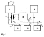
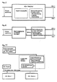
- the AS-i bus consists of two multiply branched lines 8, 9 which are connected to the output of the power supply unit 1, to the slaves S1, S2, S3 or to the master 1.
- the power supply unit 1 draws energy via primary lines 2, 3 and supplies the slaves S1, S2, S3 and the master M with power via the AS-i bus 8, 9.
- Each slave S1, S2, S3 has a binary address and can be called by modulating on such a sequence of transmission pulses on the AS-i bus 8.9, which corresponds to the binary address of the slave.
- the generation of the transmission pulses can be done in particular by the master 1; Alternatively, an own addressing device, which e.g. temporarily connected to the AS-i bus 8,9 for control purposes.
- the called slave issues a response signal in response to the call by modulating a sequence of response pulses onto the AS-i bus 8, 9 by pulling a correspondingly higher current, transmit current, from the power supply unit 1.
- the current output by the power supply unit 1 is thus changed by modulating the response pulses on the AS-i bus 8, 9.
- the current change triggered by a response pulse is typically 60mA, for example.
- this current change typically increases to about twice this value, ie typically to 120 mA, for example.
- the fluctuations which the current supplied by the power supply unit 1 is subjected to are used for the purpose of detecting a superposition of the response signals of two or more slaves.
- the transformer 6, 7, which has a first and second winding 6, 7, serves to supply the caused by the response pulses current changes of the monitoring device 10.
- the first winding 6 of the transformer 6,7 is interposed between the power supply unit 1 and a line 8 of the AS-i bus 8,9, so that the variations in the output from the second winding 7 voltage is a measure of the variations are output from the power supply unit 1 amperage.
- the monitoring device 10 thus detects the current fluctuations caused by the response pulses, compares their amplitude with a predetermined threshold and triggers a switching or warning signal if the threshold is exceeded.
- the threshold is chosen so that when a single slave issues a response signal, the threshold is not exceeded, and then, when the response signals of two or more slaves overlap, the threshold is exceeded.
- the threshold may e.g. be chosen so that at an amplitude of the current fluctuation of 65mA, the switching or warning signal is triggered.
- the switching or warning signal is thus triggered according to the invention, if at least two slaves have the same binary address, these slaves have been caused by a sequence, in particular one and the same sequence of transmit pulses simultaneously to the delivery of each response signal and superimpose these response signals.
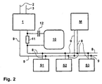
- FIG 2 shows another embodiment of an actuator-sensor interface system according to the invention with the power supply unit 1, the master M, the three slaves S1, S2, S3, the AS-i bus 8,9 and with the monitoring device 10 of FIG 1 and with a resistor 11 which is interposed between the power supply unit 1 and the one line 8 of the AS-i bus 8, 9 so that the voltage drop across the resistor 11 is a measure of the current output by the power supply unit 1 ,
- the voltage drop occurring at the resistor 11 is tapped off and fed to the monitoring device 10 via a capacitor 12.
- the capacitor 12 acts as a barrier for the temporally constant portion of the tapped voltage, so that only voltage fluctuations reach the monitoring unit 10.
- This thus detects the variations in the voltage drop, compares their amplitude with a predetermined threshold and triggers a switching or warning signal if the threshold is exceeded.
- the threshold is chosen so that when a single slave issues a response signal, the threshold is not exceeded, and then, when the response signals of two or more slaves overlap, the threshold is exceeded.
- the switching or warning signal is thus triggered according to the invention, if at least two slaves have the same binary address, these slaves by a Sequence, in particular one and the same sequence, have been caused by transmitting pulses simultaneously to the delivery of each response signal and superimpose these response signals.
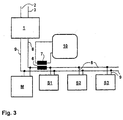
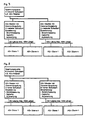
- FIG. 3 shows a further embodiment of an actuator-sensor interface system according to the invention with the power supply unit 1, the master M, the three slaves S1, S2, S3, the AS-i bus 8, 9, the transformers 6, 7 and the monitoring device 10.
- the topology of the circuit is changed compared to FIG. Starting from the power supply unit 1, the master M and then the slaves S1, S2, S3 are connected to the AS-i bus along the AS-i bus 8, 9 first.
- the current flowing in the AS-i bus is changed by modulating the response pulses on the AS-i bus.
- the first winding 6 of the transformer 6, 7 is interposed between the master M and the slave S1 in the line 8 of the AS-i bus 8, 9, so that the fluctuations of the output from the second winding 7 Voltage is a measure of the fluctuations in the current flowing in the AS-i bus.
- the triggered by a response pulse current change in the AS-i bus is about half as large as that change in current in the AS-i bus, which occurs at superposition of two response pulses.
- the fluctuations which the current flowing in the AS-i bus is subjected to is used according to the invention for the purpose of detecting a superposition of the response signals of two or more slaves.
- the voltage delivered by the second winding 7 is supplied to the monitoring device 10. This detects the output from the second winding 7 voltage and determines the temporal behavior of the amplitude of the fluctuations in the current flowing in the AS-i bus current.
- the monitoring device 10 thus detects the current fluctuations caused by the response pulses in the AS-i bus, compares their amplitude with a predetermined threshold and triggers a switching or warning signal, if the threshold is exceeded.
- the threshold is chosen so that when a single slave issues a response signal, the threshold is not exceeded, and then, when the response signals of two slaves overlap, the threshold is exceeded.
- the switching or warning signal is thus triggered according to the invention, if at least two slaves have the same binary address, these slaves have been caused by a sequence, in particular one and the same sequence of transmit pulses simultaneously to the delivery of each response signal and superimpose these response signals.
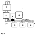
- FIG. 4 shows a further embodiment of an actuator-sensor interface system according to the invention with the power supply unit 1, the master M, the three slaves S1, S2, S3, the AS-i bus 8, 9, the transformer 6, 7 and the monitoring device 10.
- the topology of the circuit is changed compared to FIG.
- the master M is interposed in between the power supply unit 1 and the AS-i bus 8.9 and contains a data uncoupling, not shown.
- the first winding 6 of the transformer 6, 7 is interposed between the master M and the slave S1 in the line 8 of the AS-i bus 8, 9, so that the fluctuations of the output from the second winding 7 Voltage is a measure of the fluctuations in the current flowing in the AS-i bus.
- the fluctuations which the current flowing in the AS-i bus is subjected to is used according to the invention for the purpose of detecting a superposition of the response signals of two or more slaves.
- the monitoring device 10 detects the output from the second winding 7 voltage and determines the temporal behavior of the amplitude of the fluctuations in the current flowing in the AS-i bus current.
- the monitoring device 10 detects the current fluctuations caused by the response pulses in the AS-i bus, compares their amplitude with a predetermined threshold and triggers the switching or warning signal if the threshold is exceeded.
- the threshold is chosen so that when a single slave issues a response signal, the threshold is not exceeded, and then, when the response signals of two or more slaves overlap, the threshold is exceeded.
- the switch or Warning signal is thus triggered if at least two slaves have the same binary address, these slaves have been caused by a sequence, in particular one and the same sequence of transmit pulses simultaneously to the delivery of each response signal and superimpose these response signals.
- FIG. 5 shows a further example of an AS-Interface power supply according to the invention.
- Figure 6 shows an example of a voltage source in low degree of protection, for example 30 V DC and a data decoupling in each case separate, wherein the data decoupling is carried out in a high degree of protection.
- Figure 7 shows an example of two AS-Interface circuits, which have two separate data decoupling according to the invention, integrated into the AS-Interface master in low degree of protection and are powered by a voltage source in low degree of protection with voltage.
- FIG. 8 is an example of two AS-Interface circuits which are missed via two separate data decouplers according to the invention, integrated into the AS-Interface masters in a high degree of protection and supplied by a low-voltage voltage source which, for example, the AS-Interface i power supply represents.
- Figure 9 shows an example of an AS-Interface circuit with two data decouplers according to the invention and a repeater, which are constructed together in high or low degree of protection, because both possibilities are given.
- Figure 10 shows an example of an AS-Interface circuit with a data decoupling according to the invention and an extender, which are constructed together in high or low degree of protection, the data decoupling again - as well as in Figure 9- equipped with the extensions current measurement and logical evaluation can be.
- FIG. 11 shows a further example of an AS-Interface circuit with a data decoupling with the extensions current measurement and logical evaluation and an AS-i ground fault monitor, which is connected to the data decoupler, whereby data decoupling and earth fault monitors can be constructed together in high or low degree of protection and the earth fault monitor is also connected to the AS-i bus.
- an AS-i bus is to be used beyond its normal AS-i line length, approximately 100 m, then in this case at least one or more repeaters, in particular two repeaters connected in series, will be inserted into the AS-i Bus, wherein the number of repeaters corresponds to the number of line segments.
- the AS-i bus is thus constructed from a number of line segments with specific AS-i cable lengths, each of which meets the AS-i requirements.
- Each line segment receives its own power supply, which in principle causes a galvanic decoupling of the individual AS-i line segments and thus also performs a data decoupling. In this case, therefore, the invention must be performed and applied to each AS-i line segment.
- the AS-i bus is thus divided into a number of line segments, which individually meet the AS-i requirements , wherein in each line segment, a repeater is inserted with its own power supply.
- the inventive method is carried out for each line segment by the response pulses are detected by a monitoring device which triggers a switching or warning signal when superimposing the response signals of two or more slaves, so that it is triggered if two or more slaves own the same binary address, these slaves are caused by a sequence, in particular one and the same sequence of transmit pulses simultaneously to the delivery of each response signal and superimpose these response signals.
- the object of the invention is in particular the unambiguous diagnostic capability of the multiple addressing by misaddressing of AS-Interface slaves during commissioning, maintenance and repair for bus systems according to the AS-Interface standard for controlling and activating each other networked and communicating binary, multiple modules, AS-Interface slaves, whereby in particular the downtime of the systems during maintenance and repair drastically shortened and thus the availability of the entire system is significantly increased.
- the data decoupling extended by the possibility of current measurement and an additional logical evaluation separated from the power source in high degree of protection, whereby the voltage source in simple protection spatially separated from the data decoupling in low or high degree of protection can be simpler and the power loss can be submitted easier.
Landscapes
- Physics & Mathematics (AREA)
- General Physics & Mathematics (AREA)
- Engineering & Computer Science (AREA)
- Automation & Control Theory (AREA)
- Arrangements For Transmission Of Measured Signals (AREA)
- Small-Scale Networks (AREA)
- Vehicle Body Suspensions (AREA)
- Control Of Electric Motors In General (AREA)
- Air Bags (AREA)
Claims (25)
- Système d'interface capteur-actionneur comprenant au moins deux esclaves (S1,S2,S3), un maître (M), un bus d'interface capteur-actionneur (8,9), bus AS-i (8,9), auquel sont connectés les esclaves (S1,S2,S3) et le maître (M), ainsi qu'un bloc d'alimentation (1) capable d'alimenter les esclaves (S1,S2,S3) en courant via le bus AS-i (8,9), chaque esclave (S1,S2,S3) possédant une adresse binaire et, par modulation sur le bus AS-i (8,9) d'une séquence d'impulsions d'émission correspondant à l'adresse binaire de l'esclave (S1,S2,S3), pouvant être appelé et incité à délivrer un signal de réponse composé d'une séquence d'impulsions de réponse modulée sur le bus AS-i par l'esclave appelé (S1,S2,S3), caractérisé par un dispositif de surveillance (10) capable de saisir les impulsions de réponse et qui, lorsque les signaux de réponse d'au moins deux esclaves se superposent, déclenche un signal de commutation ou un signal avertisseur, de sorte que celui-ci est déclenché lorsqu'au moins deux esclaves (S1,S2,S3) possèdent la même adresse binaire, que lesdits esclaves (S1,S2,S3) ont été incités par une séquence d'impulsions d'émission à délivrer simultanément chacun son signal de réponse et que ces signaux de réponse se superposent.
- Système d'interface capteur-actionneur selon la revendication 1, caractérisé en ce que celui-ci est capable- de moduler sur le bus AS-i (8,9), en séquence cyclique, un nombre de séquences différentes d'impulsions d'émission correspondant au nombre d'esclaves (S1,S2,S3) du système d'interface capteur-actionneur et- d'observer entre deux séquences d'impulsions d'émission une pause d'émission, pendant laquelle il ne se produit aucune modulation d'impulsion d'émission sur le bus AS-i (8,9).
- Système d'interface capteur-actionneur selon l'une des revendications 1 ou 2, caractérisé en ce que le dispositif de surveillance (10) est en mesure de reconnaître une superposition de deux signaux de réponse à ce que que l'amplitude des fluctuations de l'intensité de courant délivrée par le bloc d'alimentation (1) ou circulant dans le bus AS-i (8,9) dépasse un seuil prédéfini.
- Système d'interface capteur-actionneur selon la revendication 3, caractérisé en ce que le seuil est supérieur au courant d'émission simple d'un esclave et inférieur au courant d'émission double d'un esclave.
- Système d'interface capteur-actionneur selon la revendication 3, caractérisé en ce que le seuil est supérieur à l'amplitude maximale des fluctuations de l'intensité de courant délivrée par le bloc d'alimentation (1) ou de l'intensité de courant circulant dans le bus AS-1 (8,9) et qui sont dues au fait qu'un esclave (S1,S2,S3) délivre un signal de réponse, et inférieur à la double valeur de ladite ampitude.
- Système d'interface capteur-actionneur selon l'une des revendications 1 à 5, caractérisé par un dispositif de décodage des signaux d'émission qui est capable de saisir les impulsions d'émission et d'identifier l'adresse dans chaque séquence d'impulsions d'émission correspondant à une adresse binaire d'un esclave (S1,S2,S3).
- Système d'interface capteur-actionneur selon la revendication 6, caractérisé en ce que le dispositif de décodage des signaux d'émission est en mesure de saisir le signal de commutation ou le signal avertisseur et, en cas de détection de ce dernier, d'afficher et/ou de mémoriser la dernière adresse identifiée d'un esclave (S1,S2,S3).
- Système d'interface capteur-actionneur selon l'une des revendications 2 à 7, caractérisé par une résistance (11) connectée entre le bloc d'alimentation (1) et une ligne (8,9) du bus AS-i (8,9) ou dans le bus AS-i de sorte que la chute de tension se produisant à la résistance (11) constitue la mesure de l'intensité de courant délivrée par le bloc d'alimentation (1) ou circulant dans le bus AS-i (8,9), le dispositif de surveillance (10) étant en mesure- soit de saisir ladite chute de tension et d'en déduire la valeur de l'intensité de courant délivrée par le bloc d'alimentation (1) ou la valeur de l'intensité de courant circulant dans le bus AS-i,- soit de saisir les fluctuations de ladite chute de tension et d'en déduire l'amplitude des fluctuations de l'intensité de courant délivrée par le bloc d'alimentation (1) ou l'amplitude des fluctuations de l'intensité de courant circulant dans le bus AS-i.
- Système d'interface capteur-actionneur selon l'une des revendications 3 à 5, caractérisé par un transformateur (6,7) comportant un premier et un deuxième enroulement (6,7), le premier enroulement (6) étant connecté- entre le bloc d'alimentation (1) et une ligne (8,9) du bus AS-i (8,9) ou- dans une ligne (8,9) du bus AS-i (8,9)de sorte que les fluctuations de la tension délivrée par le deuxième enroulement (7) constituent la mesure- des fluctuations de l'intensité de courant délivrée par le bloc d'alimentation (1) ou- des fluctuations de l'intensité de courant circulant dans le bus AS-i (8,9)et le dispositif de surveillance (10) étant capable de saisir la tension délivrée par le deuxième enroulement (7) et de déterminer à partir de l'allure dans le temps de celle-ci- l'amplitude des fluctuations de l'intensité de courant délivrée par le bloc d'alimentation (1) ou- l'amplitude des fluctuations de l'intensité de courant circulant dans le bus AS-i (8,9).
- Système d'interface capteur-actionneur selon la revendication 2 et l'une des revendications 10 ou 11, caractérisé en ce que le dispositif de décodage des signaux d'émission est en mesure de saisir les impulsions de réponse apparaissant pendant chaque pause d'émission et, en cas d'absence de celles-ci pendant une pause d'émission, d'afficher et/ou de mémoriser la dernière adresse identifiée d'un esclave (S1,S2,S3).
- Système d'interface capteur-actionneur selon la revendication 10, caractérisé en ce que le dispositif de décodage des signaux d'émission est capable de déclencher un signal d'erreur en cas d'absence d'impulsions de réponse pendant une pause d'émission.
- Système d'interface capteur-actionneur selon l'une des revendications 1 à 11, caractérisé en ce que le bloc d'alimentation (1) comprend une source de courant ainsi qu'un découplage de données, le découplage de données étant connecté entre la source de courant et le bus AS-i (8,9).
- Système d'interface capteur-actionneur selon l'une des revendications 1 à 12, caractérisé en ce que le bloc d'alimentation (1) et le dispositif de surveillance (10) ainsi que, le cas échéant, le dispositif de décodage des signaux d'émission et le dispositif de surveillance (10) sont disposés dans le même boîtier.
- Procédé destiné à commander un système d'interface capteur-actionneur comprenant au moins deux esclaves (S1,S2,S3), un maître (M), un bus d'interface capteur-actionneur (8,9), bus AS-i (8,9), auquel sont connectés les esclaves (S1,S2,S3) et le maître (M), ainsi qu'un bloc d'alimentation (1) capable d'alimenter les esclaves (S1,S2,S3) en courant via le bus AS-i (8,9), chaque esclave (S1,S2,S3) possédant une adresse binaire et, en modulant sur le bus AS-i (8,9) une séquence d'impulsions d'émission correspondant à l'adresse binaire de l'esclave (S1,S2,S3), pouvant être appelé et incité à délivrer un signal de réponse composé d'une séquence d'impulsions de réponse modulée sur le bus AS-i par l'esclave appelé (S1,S2,S3), caractérisé en ce que
les impulsions de réponse sont saisies par un dispositif de surveillance (10) qui, lorsque les signaux de réponse d'au moins deux esclaves se superposent, déclenche un signal de commutation ou un signal avertisseur, de sorte que celui-ci est déclenché lorsqu'au moins deux esclaves (S1,S2,S3) possèdent la même adresse binaire, que lesdits esclaves (S1,S2,S3) sont incités par une séquence, en particulier par une même séquence d'impulsions d'émission, à délivrer simultanément chacun son signal de réponse et que ces signaux de réponse se superposent. - Procédé selon la revendication 19, caractérisé en ce que, en séquence cyclique, autant de séquences différentes d'impulsions d'émission sont modulées sur le bus AS-i que le système d'interface capteur-actionneur possède d'esclaves (S1,S2,S3) et qu'on observe entre deux séquences d'impulsions d'émission une pause d'émission, pendant laquelle aucune impulsion d'émission n'est modulée sur le bus AS-i (8,9).
- Procédé selon la revendication 14 ou 15, caractérisé en ce que le dispositif de surveillance (10) utilisé est capable de reconnaître une superposition de deux signaux de réponse à ce que l'amplitude des fluctuations de l'intensité de courant- délivrée par le bloc d'alimentation (1) ou- circulant dans le bus AS-i (8,9)dépasse un premier seuil prédéfini.
- Procédé selon la revendication 16, caractérisé en ce qu'on choisit un seuil supérieur à l'amplitude maximale des fluctuations de l'intensité de courant délivrée par le bloc d'alimentation (1) ou de l'intensité de courant circulant dans le bus AS-i (8,9) et qui sont dues au fait qu'un esclave (S1,S2,S3) délivre un signal de réponse, et inférieur au double de ladite amplitude.
- Système d'interface capteur-actionneur selon la revendication 17, caractérisé en ce que le seuil choisi est supérieur à 1,1 fois l'amplitude maximale des fluctuations de l'intensité de courant délivrée par le bloc d'alimentation (1) ou de l'intensité de courant circulant dans le bus AS-i (8,9) et qui sont dues au fait qu'un esclave (S1,S2,S3) délivre un signal de réponse, et inférieur à 1,9 fois cette amplitude.
- Procédé selon l'une des revendications 19 à 27, caractérisé en ce que les impulsions d'émission sont saisies au moyen d'un dispositif de décodage des signaux d'émission qui est capable d'identifier dans chaque séquence d'impulsions d'émission l'adresse correspondant à une adresse binaire d'un esclave (S1,S2,S3).
- Procédé selon la revendication 19, caractérisé en ce que le signal de commutation ou le signal avertisseur est saisi et que, en cas de détection de ce dernier, la dernière adresse identifiée d'un esclave (S1,S2,S3) est affichée et/ou stockée.
- Procédé selon l'une des revendications 14 à 20, caractérisé en ce que la chute de tension se produisant à une résistance (11) connectée entre le bloc d'alimentation (10) et une ligne (8,9) du bus AS-i (8,9) ou dans le bus AS-i (8,9) est prélevée, acheminée vers le dispositif de surveillance et utilisée en tant que mesure de l'intensité de courant délivrée par le bloc d'alimentation (1) ou circulant dans le bus AS-i (8,9), et que
soit ladite chute de tension est utilisée pour déterminer la valeur de l'intensité de courant délivrée par le bloc d'alimentation (1) ou la valeur de l'intensité de courant circulant dans le bus AS-i (8,9),
soit les fluctuations de ladite chute de tension sont utilisées pour déterminer l'amplitude des fluctuations de l'intensité de courant délivrée par le bloc d'alimentation (1) ou l'amplitude des fluctuations de l'intensité de courant circulant dans le bus AS-i (8,9). - Procédé selon l'une des revendications 14 à 21, caractérisé en ce qu' un transformateur (6,7) comportant un premier et un deuxième enroulement (6,7) est utilisé, le premier enroulement (6) étant connecté entre le bloc d'alimentation (1) et une ligne (8,9) du bus AS-i (8,9)
ou
dans une ligne (8,9) du bus AS-i (8,9), que les fluctuations de la tension délivrée par le deuxième enroulement (7) sont utilisées en tant que mesure des fluctuations de l'intensité de courant délivrée par le bloc d'alimentation (1) ou des fluctuations de l'intensité de courant circulant dans le bus AS-i (8,9) et que l'on détermine, à partir de l'allure dans le temps de la tension délivrée par le deuxième enroulement (7), l'amplitude des fluctuations de l'intensité de courant délivrée par le bloc d'alimentation (1) ou l'amplitude des fluctuations de l'intensité de courant circulant dans le bus AS-i (8,9). - Procédé selon l'une des revendications 14 à 22, caractérisé en ce que les impulsions de réponse apparaissant pendant chaque pause d'émission sont saisies et, en cas d'absence de celles-ci pendant une pause d'émission, la dernière adresse identifiée d'un esclave (S1,S2,S3) est affichée et/ou mémorisée.
- Procédé selon la revendication 23, caractérisé en ce qu'un signal d'erreur est déclenché en cas d'absence d'impulsions de réponse pendant une pause d'émission.
- Procédé selon l'une des revendications précédentes, caractérisé en ce que, lorsqu'on utilise un bus AS-i dont la longueur de ligne AS-i normale est supérieure aux spécifications AS-i, le bus AS-i est subdivisé en plusieurs segments de ligne qui, pris isolément, répondent aux exigences AS-i, en insérant dans chaque segment de ligne un répéteur doté de son propre bloc secteur, via lequel répéteur s'effectue le procédé selon la revendication 19.
Applications Claiming Priority (2)
| Application Number | Priority Date | Filing Date | Title |
|---|---|---|---|
| DE10156148 | 2001-11-15 | ||
| DE10156148 | 2001-11-15 |
Publications (3)
| Publication Number | Publication Date |
|---|---|
| EP1312991A2 EP1312991A2 (fr) | 2003-05-21 |
| EP1312991A3 EP1312991A3 (fr) | 2005-11-30 |
| EP1312991B1 true EP1312991B1 (fr) | 2007-03-07 |
Family
ID=7705864
Family Applications (1)
| Application Number | Title | Priority Date | Filing Date |
|---|---|---|---|
| EP02025463A Expired - Lifetime EP1312991B1 (fr) | 2001-11-15 | 2002-11-15 | Système d'interface actionneur capteur et procédé pour le commander |
Country Status (3)
| Country | Link |
|---|---|
| EP (1) | EP1312991B1 (fr) |
| AT (1) | ATE356376T1 (fr) |
| DE (2) | DE10253566A1 (fr) |
Cited By (3)
| Publication number | Priority date | Publication date | Assignee | Title |
|---|---|---|---|---|
| DE102009033229A1 (de) | 2009-07-14 | 2011-01-27 | Bihl+Wiedemann Gmbh | Verfahren zur Erkennung von Doppeladressierungen in AS Interface Netzen |
| DE102011101172A1 (de) | 2011-05-11 | 2012-11-15 | Andreas Schiff | Mehrfachadresserkennung in AS-Interface-Netzwerken |
| US10286337B1 (en) | 2018-03-08 | 2019-05-14 | Mark W. Romers | Filter backwash control system for a water or wastewater treatment system to conserve water during the filter backwash process |
Families Citing this family (16)
| Publication number | Priority date | Publication date | Assignee | Title |
|---|---|---|---|---|
| US7319921B2 (en) * | 2002-05-22 | 2008-01-15 | Underwood Fred R | Water treatment control system |
| EP1898287A1 (fr) * | 2006-09-05 | 2008-03-12 | Siemens Aktiengesellschaft | Réseau ASI pour des environnements en danger d'explosion |
| DE102007025852B3 (de) | 2007-06-01 | 2009-01-02 | I F M Electronic Gmbh | Überwachungseinrichtung zur Erkennung einer fehlerhaften Adressierung eines Aktuator-Sensor-Interface-Slaves |
| EP2254011B1 (fr) * | 2009-05-20 | 2012-08-01 | Siemens Aktiengesellschaft | Alimentation en énergie d'une interface AS |
| EP2348374B1 (fr) * | 2010-01-18 | 2012-11-28 | Siemens Aktiengesellschaft | Procédé de détection d'un adressage multiple défectueux d'un réseau fonctionnant selon le principe maître-esclave et un réseau à interface de capteur d'actionneur correspondant |
| DE102011080550B4 (de) * | 2010-08-05 | 2019-02-07 | Ifm Electronic Gmbh | Mastereinheit mit Erweiterungsmodul für ein Bussystem der Automatisierungstechnik |
| WO2013013710A1 (fr) | 2011-07-27 | 2013-01-31 | Siemens Aktiengesellschaft | Détection d'un adressage multiple défectueux à l'intérieur d'un système d'interface actionneur-capteur |
| DE102012202424A1 (de) * | 2012-02-16 | 2013-08-22 | Ifm Electronic Gmbh | Erdschlusswächter für ein ASi-Sensor-Aktor-Netzwerk |
| DE102013216564B4 (de) | 2013-08-21 | 2021-04-22 | Ifm Electronic Gmbh | Verfahren zur Erkennung einer Doppeladressierung von Slaves in einem Master-Slave-Bussystem |
| DE102014117590A1 (de) * | 2014-12-01 | 2016-06-02 | Logicdata Electronic & Software Entwicklungs Gmbh | Elektrisch verstellbares Tischsystem und Verfahren zur Herstellung eines elektrisch verstellbaren Tischsystems |
| DE102016110641B3 (de) * | 2016-06-09 | 2017-11-16 | Beckhoff Automation Gmbh | Feldbusmodul und Verfahren zum Betreiben eines Feldbussystems |
| DE102016221139B4 (de) * | 2016-10-26 | 2018-12-13 | SPX Flow Technology Rosista GmbH | AS-i Netzwerk und Betriebsverfahren |
| DE102017128249B4 (de) | 2017-11-29 | 2022-02-17 | Ifm Electronic Gmbh | Anordnung für einen Aktuator-Sensor Interface Feldbus (AS-i-Bus) mit einem Diagnosegerät |
| CN110579989A (zh) * | 2019-09-12 | 2019-12-17 | 武汉介观生物科技有限责任公司 | 一种支持通用传感和执行器的双系统程控设备 |
| FI20205433A1 (en) * | 2020-04-28 | 2021-10-29 | Spindrive Oy | Control system for controlling a magnetic suspension system |
| DE102022126354B3 (de) | 2022-10-11 | 2023-12-21 | Ifm Electronic Gmbh | Verfahren zur automatischen Adressvergabe in einem AS-I-Master-Slave-Bussystem |
Family Cites Families (3)
| Publication number | Priority date | Publication date | Assignee | Title |
|---|---|---|---|---|
| FR2664715B1 (fr) * | 1990-07-13 | 1994-01-21 | Moulinex | Procede d'attribution d'adresses dans un reseau domotique. |
| DE9416127U1 (de) * | 1994-10-06 | 1994-12-08 | Siemens AG, 80333 München | Modul für ein Aktuator-Sensor-Interface-System |
| DE19947501C5 (de) * | 1999-10-01 | 2016-06-30 | Ifm Electronic Gmbh | Aktuator-Sensor-Interface-Slave |
-
2002
- 2002-11-15 DE DE10253566A patent/DE10253566A1/de not_active Withdrawn
- 2002-11-15 DE DE50209644T patent/DE50209644D1/de not_active Expired - Lifetime
- 2002-11-15 AT AT02025463T patent/ATE356376T1/de not_active IP Right Cessation
- 2002-11-15 EP EP02025463A patent/EP1312991B1/fr not_active Expired - Lifetime
Cited By (4)
| Publication number | Priority date | Publication date | Assignee | Title |
|---|---|---|---|---|
| DE102009033229A1 (de) | 2009-07-14 | 2011-01-27 | Bihl+Wiedemann Gmbh | Verfahren zur Erkennung von Doppeladressierungen in AS Interface Netzen |
| DE102009033229B4 (de) | 2009-07-14 | 2018-07-12 | Bihl+Wiedemann Gmbh | Verfahren zur Erkennung von Doppeladressierungen in AS Interface Netzen |
| DE102011101172A1 (de) | 2011-05-11 | 2012-11-15 | Andreas Schiff | Mehrfachadresserkennung in AS-Interface-Netzwerken |
| US10286337B1 (en) | 2018-03-08 | 2019-05-14 | Mark W. Romers | Filter backwash control system for a water or wastewater treatment system to conserve water during the filter backwash process |
Also Published As
| Publication number | Publication date |
|---|---|
| DE10253566A1 (de) | 2003-05-28 |
| DE50209644D1 (de) | 2007-04-19 |
| ATE356376T1 (de) | 2007-03-15 |
| EP1312991A3 (fr) | 2005-11-30 |
| EP1312991A2 (fr) | 2003-05-21 |
Similar Documents
| Publication | Publication Date | Title |
|---|---|---|
| EP1312991B1 (fr) | Système d'interface actionneur capteur et procédé pour le commander | |
| DE10392421B4 (de) | Handdiagnose- und kommunikationsgerät mit automatischer Buserkennung | |
| DE102016110641B3 (de) | Feldbusmodul und Verfahren zum Betreiben eines Feldbussystems | |
| EP2000866B1 (fr) | Dispositif de surveillance destiné à la reconnaissance d'un adressage incorrect d'un esclave dans un système de bus de terrain | |
| EP2720098B1 (fr) | Système de sécurité pour une installation comprenant un chemin de signal de test avec un chemin de retour | |
| EP2359539B1 (fr) | Protocole de transmission de données | |
| WO2003094001A1 (fr) | Procede d'adressage de dispositifs utilisateurs d'un systeme a bus au moyen de courants d'identification | |
| DE4340048A1 (de) | Vorrichtung zum Austauschen von Daten und Verfahren zum Betreiben der Vorrichtung | |
| EP2745081A1 (fr) | Module capteur pour la détection d'un paramètre de fonctionnement, procédé de surveillance d'un module capteur | |
| EP2917795B1 (fr) | Procédé d'identification de la position de montage relative des modules utilisés dans un système électronique modulaire | |
| EP1687681A2 (fr) | Reseau, notamment reseau pa profibus, a proprietes de redondance, element de ramification pour appareil d'abonne dans un reseau de ce type, gestionnaire de redondance pour un reseau de ce type et procede pour faire fonctionner un reseau de ce type | |
| EP3116169A1 (fr) | Systeme de transmission de donnees a modulation de courant | |
| WO2012000996A2 (fr) | Procédé et dispositif pour faire fonctionner des appareils de terrain, notamment des appareils de terrain hart en mode de fonctionnement multipoint | |
| DE69213505T2 (de) | Mehrfachadapter mit einer Schaltung zur Antwortssignaldetektion | |
| EP3387789B1 (fr) | Système de bus comprenant un premier ensemble d'abonnés et procédé pour faire fonctionner un système de bus | |
| DE19947501C5 (de) | Aktuator-Sensor-Interface-Slave | |
| EP2348374B1 (fr) | Procédé de détection d'un adressage multiple défectueux d'un réseau fonctionnant selon le principe maître-esclave et un réseau à interface de capteur d'actionneur correspondant | |
| DE4336698C2 (de) | Servoregler | |
| DE102009016972B4 (de) | Kommunikationssystem zum dezentralen und autarken Überwachen und Steuern eines unterlagerten Bussystems | |
| DE102009033229A1 (de) | Verfahren zur Erkennung von Doppeladressierungen in AS Interface Netzen | |
| DE202008003988U1 (de) | Busknoten eines Profinet-Bussystems | |
| DE4429278C2 (de) | Funktionseinheit | |
| DE3030252C2 (de) | Verfahren und Schaltungsanordnung zur Erfassung der Schaltzustände einer Vielzahl von peripheren Schaltern | |
| EP1170645A2 (fr) | Méthode et dispositif de surveillance et commande de machines, par exemple des installations industrielles | |
| DE102020106648A1 (de) | Technik zur Energieversorgung und Kommunikation in einem Leistungsschutzsystem |
Legal Events
| Date | Code | Title | Description |
|---|---|---|---|
| PUAI | Public reference made under article 153(3) epc to a published international application that has entered the european phase |
Free format text: ORIGINAL CODE: 0009012 |
|
| AK | Designated contracting states |
Designated state(s): AT BE BG CH CY CZ DE DK EE ES FI FR GB GR IE IT LI LU MC NL PT SE SK TR |
|
| AX | Request for extension of the european patent |
Extension state: AL LT LV MK RO SI |
|
| PUAL | Search report despatched |
Free format text: ORIGINAL CODE: 0009013 |
|
| AK | Designated contracting states |
Kind code of ref document: A3 Designated state(s): AT BE BG CH CY CZ DE DK EE ES FI FR GB GR IE IT LI LU MC NL PT SE SK TR |
|
| AX | Request for extension of the european patent |
Extension state: AL LT LV MK RO SI |
|
| 17P | Request for examination filed |
Effective date: 20051109 |
|
| AKX | Designation fees paid |
Designated state(s): AT BE BG CH CY CZ DE DK EE ES FI FR GB GR IE IT LI LU MC NL PT SE SK TR |
|
| GRAP | Despatch of communication of intention to grant a patent |
Free format text: ORIGINAL CODE: EPIDOSNIGR1 |
|
| GRAS | Grant fee paid |
Free format text: ORIGINAL CODE: EPIDOSNIGR3 |
|
| GRAA | (expected) grant |
Free format text: ORIGINAL CODE: 0009210 |
|
| AK | Designated contracting states |
Kind code of ref document: B1 Designated state(s): AT BE BG CH CY CZ DE DK EE ES FI FR GB GR IE IT LI LU MC NL PT SE SK TR |
|
| PG25 | Lapsed in a contracting state [announced via postgrant information from national office to epo] |
Ref country code: IE Free format text: LAPSE BECAUSE OF FAILURE TO SUBMIT A TRANSLATION OF THE DESCRIPTION OR TO PAY THE FEE WITHIN THE PRESCRIBED TIME-LIMIT Effective date: 20070307 Ref country code: FI Free format text: LAPSE BECAUSE OF FAILURE TO SUBMIT A TRANSLATION OF THE DESCRIPTION OR TO PAY THE FEE WITHIN THE PRESCRIBED TIME-LIMIT Effective date: 20070307 Ref country code: NL Free format text: LAPSE BECAUSE OF FAILURE TO SUBMIT A TRANSLATION OF THE DESCRIPTION OR TO PAY THE FEE WITHIN THE PRESCRIBED TIME-LIMIT Effective date: 20070307 |
|
| REG | Reference to a national code |
Ref country code: GB Ref legal event code: FG4D Free format text: NOT ENGLISH |
|
| REG | Reference to a national code |
Ref country code: CH Ref legal event code: EP |
|
| REF | Corresponds to: |
Ref document number: 50209644 Country of ref document: DE Date of ref document: 20070419 Kind code of ref document: P |
|
| REG | Reference to a national code |
Ref country code: IE Ref legal event code: FG4D Free format text: LANGUAGE OF EP DOCUMENT: GERMAN |
|
| PG25 | Lapsed in a contracting state [announced via postgrant information from national office to epo] |
Ref country code: SE Free format text: LAPSE BECAUSE OF FAILURE TO SUBMIT A TRANSLATION OF THE DESCRIPTION OR TO PAY THE FEE WITHIN THE PRESCRIBED TIME-LIMIT Effective date: 20070607 |
|
| PG25 | Lapsed in a contracting state [announced via postgrant information from national office to epo] |
Ref country code: ES Free format text: LAPSE BECAUSE OF FAILURE TO SUBMIT A TRANSLATION OF THE DESCRIPTION OR TO PAY THE FEE WITHIN THE PRESCRIBED TIME-LIMIT Effective date: 20070618 |
|
| PG25 | Lapsed in a contracting state [announced via postgrant information from national office to epo] |
Ref country code: PT Free format text: LAPSE BECAUSE OF FAILURE TO SUBMIT A TRANSLATION OF THE DESCRIPTION OR TO PAY THE FEE WITHIN THE PRESCRIBED TIME-LIMIT Effective date: 20070807 |
|
| NLV1 | Nl: lapsed or annulled due to failure to fulfill the requirements of art. 29p and 29m of the patents act | ||
| GBV | Gb: ep patent (uk) treated as always having been void in accordance with gb section 77(7)/1977 [no translation filed] |
Effective date: 20070307 |
|
| REG | Reference to a national code |
Ref country code: IE Ref legal event code: FD4D |
|
| EN | Fr: translation not filed | ||
| PG25 | Lapsed in a contracting state [announced via postgrant information from national office to epo] |
Ref country code: GB Free format text: LAPSE BECAUSE OF FAILURE TO SUBMIT A TRANSLATION OF THE DESCRIPTION OR TO PAY THE FEE WITHIN THE PRESCRIBED TIME-LIMIT Effective date: 20070307 Ref country code: SK Free format text: LAPSE BECAUSE OF FAILURE TO SUBMIT A TRANSLATION OF THE DESCRIPTION OR TO PAY THE FEE WITHIN THE PRESCRIBED TIME-LIMIT Effective date: 20070307 |
|
| PG25 | Lapsed in a contracting state [announced via postgrant information from national office to epo] |
Ref country code: CZ Free format text: LAPSE BECAUSE OF FAILURE TO SUBMIT A TRANSLATION OF THE DESCRIPTION OR TO PAY THE FEE WITHIN THE PRESCRIBED TIME-LIMIT Effective date: 20070307 |
|
| PLBE | No opposition filed within time limit |
Free format text: ORIGINAL CODE: 0009261 |
|
| STAA | Information on the status of an ep patent application or granted ep patent |
Free format text: STATUS: NO OPPOSITION FILED WITHIN TIME LIMIT |
|
| PG25 | Lapsed in a contracting state [announced via postgrant information from national office to epo] |
Ref country code: DK Free format text: LAPSE BECAUSE OF FAILURE TO SUBMIT A TRANSLATION OF THE DESCRIPTION OR TO PAY THE FEE WITHIN THE PRESCRIBED TIME-LIMIT Effective date: 20070307 |
|
| 26N | No opposition filed |
Effective date: 20071210 |
|
| PG25 | Lapsed in a contracting state [announced via postgrant information from national office to epo] |
Ref country code: IT Free format text: LAPSE BECAUSE OF FAILURE TO SUBMIT A TRANSLATION OF THE DESCRIPTION OR TO PAY THE FEE WITHIN THE PRESCRIBED TIME-LIMIT Effective date: 20070307 Ref country code: GR Free format text: LAPSE BECAUSE OF FAILURE TO SUBMIT A TRANSLATION OF THE DESCRIPTION OR TO PAY THE FEE WITHIN THE PRESCRIBED TIME-LIMIT Effective date: 20070608 Ref country code: FR Free format text: LAPSE BECAUSE OF FAILURE TO SUBMIT A TRANSLATION OF THE DESCRIPTION OR TO PAY THE FEE WITHIN THE PRESCRIBED TIME-LIMIT Effective date: 20071026 |
|
| BERE | Be: lapsed |
Owner name: BIHL + WIEDEMANN G.M.B.H. Effective date: 20071130 |
|
| PG25 | Lapsed in a contracting state [announced via postgrant information from national office to epo] |
Ref country code: MC Free format text: LAPSE BECAUSE OF NON-PAYMENT OF DUE FEES Effective date: 20071130 |
|
| PG25 | Lapsed in a contracting state [announced via postgrant information from national office to epo] |
Ref country code: CH Free format text: LAPSE BECAUSE OF NON-PAYMENT OF DUE FEES Effective date: 20071130 Ref country code: LI Free format text: LAPSE BECAUSE OF NON-PAYMENT OF DUE FEES Effective date: 20071130 |
|
| REG | Reference to a national code |
Ref country code: CH Ref legal event code: PL |
|
| PG25 | Lapsed in a contracting state [announced via postgrant information from national office to epo] |
Ref country code: BE Free format text: LAPSE BECAUSE OF NON-PAYMENT OF DUE FEES Effective date: 20071130 |
|
| PG25 | Lapsed in a contracting state [announced via postgrant information from national office to epo] |
Ref country code: FR Free format text: LAPSE BECAUSE OF FAILURE TO SUBMIT A TRANSLATION OF THE DESCRIPTION OR TO PAY THE FEE WITHIN THE PRESCRIBED TIME-LIMIT Effective date: 20070307 |
|
| PG25 | Lapsed in a contracting state [announced via postgrant information from national office to epo] |
Ref country code: EE Free format text: LAPSE BECAUSE OF FAILURE TO SUBMIT A TRANSLATION OF THE DESCRIPTION OR TO PAY THE FEE WITHIN THE PRESCRIBED TIME-LIMIT Effective date: 20070307 |
|
| PG25 | Lapsed in a contracting state [announced via postgrant information from national office to epo] |
Ref country code: AT Free format text: LAPSE BECAUSE OF NON-PAYMENT OF DUE FEES Effective date: 20071115 |
|
| PG25 | Lapsed in a contracting state [announced via postgrant information from national office to epo] |
Ref country code: CY Free format text: LAPSE BECAUSE OF FAILURE TO SUBMIT A TRANSLATION OF THE DESCRIPTION OR TO PAY THE FEE WITHIN THE PRESCRIBED TIME-LIMIT Effective date: 20070307 |
|
| PG25 | Lapsed in a contracting state [announced via postgrant information from national office to epo] |
Ref country code: LU Free format text: LAPSE BECAUSE OF NON-PAYMENT OF DUE FEES Effective date: 20071115 Ref country code: BG Free format text: LAPSE BECAUSE OF FAILURE TO SUBMIT A TRANSLATION OF THE DESCRIPTION OR TO PAY THE FEE WITHIN THE PRESCRIBED TIME-LIMIT Effective date: 20070607 |
|
| PG25 | Lapsed in a contracting state [announced via postgrant information from national office to epo] |
Ref country code: TR Free format text: LAPSE BECAUSE OF FAILURE TO SUBMIT A TRANSLATION OF THE DESCRIPTION OR TO PAY THE FEE WITHIN THE PRESCRIBED TIME-LIMIT Effective date: 20070307 |
|
| PGFP | Annual fee paid to national office [announced via postgrant information from national office to epo] |
Ref country code: DE Payment date: 20211130 Year of fee payment: 20 |
|
| REG | Reference to a national code |
Ref country code: DE Ref legal event code: R071 Ref document number: 50209644 Country of ref document: DE |