EP1313201A2 - Methode und Vorrichtung zur Bewicklung der Kerne elektrischer Machinen - Google Patents
Methode und Vorrichtung zur Bewicklung der Kerne elektrischer Machinen Download PDFInfo
- Publication number
- EP1313201A2 EP1313201A2 EP02025479A EP02025479A EP1313201A2 EP 1313201 A2 EP1313201 A2 EP 1313201A2 EP 02025479 A EP02025479 A EP 02025479A EP 02025479 A EP02025479 A EP 02025479A EP 1313201 A2 EP1313201 A2 EP 1313201A2
- Authority
- EP
- European Patent Office
- Prior art keywords
- coil
- wire
- coils
- lead
- winding
- Prior art date
- Legal status (The legal status is an assumption and is not a legal conclusion. Google has not performed a legal analysis and makes no representation as to the accuracy of the status listed.)
- Granted
Links
Images


Classifications
-
- H—ELECTRICITY
- H02—GENERATION; CONVERSION OR DISTRIBUTION OF ELECTRIC POWER
- H02K—DYNAMO-ELECTRIC MACHINES
- H02K15/00—Processes or apparatus specially adapted for manufacturing, assembling, maintaining or repairing of dynamo-electric machines
- H02K15/08—Forming windings by laying conductors into or around core parts
- H02K15/085—Forming windings by laying conductors into or around core parts by laying conductors into slotted stators
-
- H—ELECTRICITY
- H02—GENERATION; CONVERSION OR DISTRIBUTION OF ELECTRIC POWER
- H02K—DYNAMO-ELECTRIC MACHINES
- H02K15/00—Processes or apparatus specially adapted for manufacturing, assembling, maintaining or repairing of dynamo-electric machines
- H02K15/30—Manufacture of winding connections
-
- Y—GENERAL TAGGING OF NEW TECHNOLOGICAL DEVELOPMENTS; GENERAL TAGGING OF CROSS-SECTIONAL TECHNOLOGIES SPANNING OVER SEVERAL SECTIONS OF THE IPC; TECHNICAL SUBJECTS COVERED BY FORMER USPC CROSS-REFERENCE ART COLLECTIONS [XRACs] AND DIGESTS
- Y10—TECHNICAL SUBJECTS COVERED BY FORMER USPC
- Y10T—TECHNICAL SUBJECTS COVERED BY FORMER US CLASSIFICATION
- Y10T29/00—Metal working
- Y10T29/49—Method of mechanical manufacture
- Y10T29/49002—Electrical device making
- Y10T29/49009—Dynamoelectric machine
-
- Y—GENERAL TAGGING OF NEW TECHNOLOGICAL DEVELOPMENTS; GENERAL TAGGING OF CROSS-SECTIONAL TECHNOLOGIES SPANNING OVER SEVERAL SECTIONS OF THE IPC; TECHNICAL SUBJECTS COVERED BY FORMER USPC CROSS-REFERENCE ART COLLECTIONS [XRACs] AND DIGESTS
- Y10—TECHNICAL SUBJECTS COVERED BY FORMER USPC
- Y10T—TECHNICAL SUBJECTS COVERED BY FORMER US CLASSIFICATION
- Y10T29/00—Metal working
- Y10T29/49—Method of mechanical manufacture
- Y10T29/49002—Electrical device making
- Y10T29/4902—Electromagnet, transformer or inductor
- Y10T29/49071—Electromagnet, transformer or inductor by winding or coiling
-
- Y—GENERAL TAGGING OF NEW TECHNOLOGICAL DEVELOPMENTS; GENERAL TAGGING OF CROSS-SECTIONAL TECHNOLOGIES SPANNING OVER SEVERAL SECTIONS OF THE IPC; TECHNICAL SUBJECTS COVERED BY FORMER USPC CROSS-REFERENCE ART COLLECTIONS [XRACs] AND DIGESTS
- Y10—TECHNICAL SUBJECTS COVERED BY FORMER USPC
- Y10T—TECHNICAL SUBJECTS COVERED BY FORMER US CLASSIFICATION
- Y10T29/00—Metal working
- Y10T29/49—Method of mechanical manufacture
- Y10T29/49002—Electrical device making
- Y10T29/49117—Conductor or circuit manufacturing
- Y10T29/49174—Assembling terminal to elongated conductor
Definitions
- the present invention concerns improved methods and apparatus for forming undulated wire coils that are placed into the cores of dynamo electric machine components.
- the invention concerns improved methods and apparatus for controlling the direction of deposit for the turns of a wire coil and for positioning the leads of the coil.
- Direction of deposit refers to the direction that winding proceeds along the axis about which the coil is wound.
- Direction of deposit does not refer to whether wire is deposited going clockwise or counter-clockwise about the just-mentioned axis. Rather, “direction of deposit” refers to which direction along (i.e., substantially parallel to) the just-mentioned axis successive turns of wire are deposited as winding proceeds.
- the general background of the invention is provided in Barrera U.S. patent 5,881,778, and Bonnacorsi et al. U.S. patent 6,386,243, which are hereby incorporated by reference herein in their entireties.
- Selective positioning of wire leads in a coil is generally done to protect the leads from interfering with operation and becoming damaged.
- the leads may be selectively positioned away from a portion of the core that will be adjacent to a relatively moving component in the finished and operating dynamo-electric machine.
- positioning is generally achieved by controlling the final lead of the wire to produce a desired position for the lead when placed within the coil.
- a single layer of coils placed at the radially innermost portion of the core may have selectively positioned wire leads that are placed away from the center of the core.
- wire coil portions may be formed from a continuous wire segment that has only a single initial lead and a single final lead.
- each coil portion is formed by winding wire turns in a single direction of deposit, with the resulting coil having an initial lead and a final lead at radially opposite locations when placed on the core.
- This arrangement of the wire leads in the continuous wire portions produces similar interference problems as in the independent wire coils, where the wire leads are exposed to the radially inner aperture and the radially outer contour of the core.
- This and other objects are accomplished by forming a series of wire coils or continuous coil portions using a programmable apparatus that controls a sequence of directions along the coil axis in which the wire turns are to be deposited, as well as a corresponding sequence of positions for the final wire leads.
- the apparatus grips an initial lead of the first wire coil in a sequence at a first location on the forming structure.
- the wire turns of the first coil are deposited in a direction along the coil axis away from the initial lead.
- the final wire lead is returned to a position along the coil axis corresponding to the initial wire turn adjacent to the initial lead.
- an initial lead of the final coil in the sequence may be gripped at a second location opposite to the first location on the forming structure.
- the wire turns are deposited in a direction along the coil axis opposite the wire turns of the first coil toward the first position.
- the series of wire coils resulting from this programmed forming process has wire leads that are each surrounded by the bridge portions of adjacent coils.
- the "bridge portions" of coils are the portions that remain outside the core at the axial ends of the core.) The leads are thereby protected from both the radially inner aperture and the radially outer contour of the core.
- the illustrative apparatus may be used to form continuous coil portions from a continuously wound wire.
- a first coil portion may be formed on the forming structure with the wire turns deposited in a first direction along the coil axis.
- the first coil portion may then be removed from the forming structure and another coil portion may be formed with the wire turns deposited in a second opposite direction along the coil axis.
- the final lead may be selectively positioned at a level (i.e., location along the coil axis) corresponding to any of the wire turns in the second coil portion.
- the resulting continuous wire portions have only one initial lead and one final lead, where at least the initial lead is positioned away from the inner aperture of the core on which the wire is ultimately deposited.
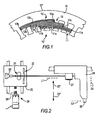
- FIG. 1 shows a component core with a plurality of wire coils placed within.
- initial lead 11a and final lead 11b have bridge portion 11c between themselves and opening 10' of the core in directions that are radial of core 10.
- Middle coil 12 may have initial lead 12a and final lead 12b positioned in the traditional manner with initial lead 12a and final lead 12b on either side of bridge portion 12c in directions that are radial of core 10, and with initial lead 12a more radially internal towards opening 10' than final lead 12b.
- initial lead 13a and final lead 13b have bridge portion 13c between themselves and the external contour 10" of the component core in directions that are radial of core 10.
- bridge portion 13c between leads 13a and 13b and the external contour 10" of the core makes leads 13a and 13b less subject to the undesirable effect of being bent outwards beyond the external contour of the core.
- FIG. 2 shows wire nozzle 20, feed device 21, and cutters 22, all of which may be mounted on support plate 23 according to the invention.
- Support plate 23 may be capable of translating in upward direction 23' and downward direction 23".
- Axis 24 may be thought of as the above-mentioned coil axis.
- Position controlled motor unit 25 may be used to rotate a screw/bush assembly 25' that drives the translation of support plate 23 in directions 23' and 23".
- the motion of support plate 23 in directions 23' and 23" may be programmable through controlled motor unit 25 to fulfill required position appointments in time and as a function of the rotational angular position of the support head about axis 24.
- forming member 26 which may be one of the forming members assembled in an annular array about axis 24 of the before-mentioned support head, may be provided with grippers 27 and 28 for holding the initial leads of the coils (e.g., leads 11a, 12a, and 13a shown in FIG. 1).
- Gripper 27 is located in upper plane L1 of the forming member, and gripper 28 is located in lower plane L2 of the forming member.
- Grippers 27 and 28 may be capable of gripping the initial lead fed from wire nozzle 20, rotating during rotation of the support head to bring the initial lead tangent to a side of the polygonal wire configuration defined by the annular array of forming members 26, and rotating during the formation of the undulated configuration.
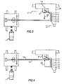
- FIGS. 3-8 show the illustrative apparatus in various operational stages for winding each of the series of coils 11, 12, and 13 shown in FIG. 1. It should be mentioned that all of these FIGS., and indeed all of the FIGS. herein that are like FIG. 2, are somewhat schematic. Thus, these FIGS. do not accurately reflect the fact that motor unit 25 is typically stationary in the vertical direction relative to forming members 26. In other words, these FIGS. do not accurately show that the vertical spacing between elements 23 and 25 changes as motor unit 25 operates. It should also be mentioned that although the following discussion tends to imply that coils 11-13 are wound in that order, the opposite order (13 first, then 12, then 11) can be used instead, if desired.
- the order in which the coils are wound can depend on the nature of the apparatus used to subsequently insert the coils in core 10. If that apparatus is capable of inserting all three coils substantially simultaneously, then the coils can be wound in the order 11, 12, 13. But if the insertion apparatus is of the type that inserts each coil as it is wound, then the coils are typically wound in the order 13, 12, 11.
- FIG. 3 shows coil 11 being started by gripping initial lead 11a with gripper 27. Wire turns 1 to 6 of coil 11 may then be progressively formed according to an order in time represented by the numbering 1 to 6 (i.e., starting from turn number 1 and gradually moving down along to coil axis to end with turn number 6).
- the formation of wire turns 1 to 6 may be obtained by rotating the support head (including forming members 26), after initial lead 11a has been gripped by gripper 27, to draw wire from nozzle 20.
- gripper 27 is shown rotated to bring initial lead 11a tangent to a side of the polygonal configuration of the wire coil formed by rotation of the support head around axis 24.
- the wire turns 1 to 6 are consecutively drawn onto forming members 26 to form the polygonal shape that is required before forming the wire coil into the undulated configuration.
- slide 23 is progressively moved in downward direction 23" along the coil axis to position turns 1 to 6 along forming members 26.
- this gradual, relative downward movement of slide 23 causes the wire to be deposited on forming members 26 in a vertically oriented helix (albeit a helix that has a polygonal annular shape).
- the successive turns of the wire in this helix are approximately in respective planes that are parallel to one another and approximately perpendicular to vertical axis 24 (the coil axis).
- the result of moving slide 23 in the manner described above is to progressively align wire nozzle 20 with predetermined positions distributed vertically along forming members 26 and consequently to achieve positioning of the wire turns in the predetermined vertically distributed positions.
- the wire turns should result according to the formation shown in FIG. 3, where the turns are positioned in a descending order vertically along forming members 26 without surmounting (i.e., radially over-lapping) each other. In this way, later insertion of the coil into the slots of the core will be achieved more smoothly and with less risk of jamming that may be caused by wire turns that surmount each other, and that do not run properly within the predefined core slots.
- slide 23 may be moved in downward direction 23" along the coil axis in increments substantially equal to the diameter of the wire used to form the turns. If multiple wires are drawn simultaneously from wire nozzle 20 to form the coils and the leads, slide 23 may be moved in downward direction 23" in increments that are a corresponding multiple of the wire diameter. The incremental movements of slide 23 may be effected as a predetermined function of the angular rotation of the support head.
- forming members 26 do not require the surface inclination traditionally used to shift the wound turns downward as new wire is drawn onto the forming members by rotation of the support head.
- FIG. 4 shows the apparatus at a time following the formation of the wire turns shown in FIG. 3.
- FIG. 4 shows the positioning of final lead 11b after turn 6 is wound onto forming members 26. Particularly, slide 23 is moved upwards in direction 23' along the coil axis to level L3, just below level L1, in order to satisfy the radial position assignment shown in FIG. 1 when the coil is placed within the core. After the instant shown in FIG. 4, final lead 11b may be cut and the undulated configuration may be formed.
- FIGS. 5 and 6 show the illustrative apparatus during operational sequences for winding coil 12 and for positioning initial lead 12a and final lead 12b into the radial positions assigned to them in FIG. 1.
- initial lead 12a is gripped by lower gripper 28 and slide 23 thereafter gradually moves in upward direction 23' along the coil axis to achieve the ascending order of turns 1 to 6 shown in FIG. 6.
- Vertical translation of slide 23 after the formation of the turns is not necessary because final lead 12b is formed at level L3 to achieve the position requirement shown in FIG. 1.
- FIGS. 7 and 8 show the illustrative apparatus during operational sequences for winding coil 13 and for positioning initial lead 13a and final lead 13b.
- initial lead 13a is gripped by lower gripper 28, and slide 23 thereafter gradually moves in upward direction 23' along the coil axis to achieve the vertically ascending order of turns 1 to 6 shown in FIG. 8.
- slide 23 is moved in downward direction 23" along the coil axis to position final lead 13b at level L4 just above level L2 of gripper 28.
- initial lead 12a and final lead 12b will be properly positioned in the position assignments shown in FIG. 1.
- the movement of slide 23 to position final lead 13b should occur as an appropriate function of the support head rotation so as to allow the descending wire to cross the previously formed turns 1 to 6 along a sufficiently ample angular distance around the coil.
- a series of coils (e.g., coils 11, 12, and 13) are formed in sequence by programmable apparatus that controls the position appointments of vertically translating slide 23 and rotating forming members 26.
- the apparatus controls the vertical positioning of the wire turns and of the wire leads for each coil being formed.
- the resulting series of coils has each initial and final lead surrounded by the bridge portions (e.g., 11c, 12c, 13c) of adjacent wire coils when placed into the core.
- the wire leads in the series of coils are exposed to neither the radially inner opening nor the radially outer contour of the core.
- Another approach to reducing the opportunity for interference from wire leads is to reduce their frequency in the core.
- One such approach uses multiple coil portions formed from a continuous wire, where the resulting continuous coil portions have only a single initial lead and a single final lead.
- a method for forming two phase-shifted, continuous half-coils is discussed in before-mentioned and incorporated Barrera U.S. patent 5,881,778.
- FIG. 9 shows a component core 10 with illustrative half coils placed therein that resulted from an exemplary method of the invention.
- the half coils of other phases that would be present in core 10 have been omitted for sake of clarity.
- half coils 90' and 90" are joined by connection loop 91 and has initial lead 90a at the beginning of half coil 90', and final lead 90b at the end of half coil 90".
- Initial lead 90a and final lead 90b are positioned so that bridging portions 90'c and 90"c act as barriers toward radially inner opening 10' for the same reasons relating to the positioning of leads 11a and 11b in FIG. 1. Note that in FIG.
- loop 91 is shown as including two wires (because in this illustrative example the windings have been made by depositing two wires simultaneously, side by side, from a single wire dispenser). If the windings had instead been made using only a single wire emanating from the wire dispenser, loop 91 would only be a single wire.
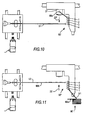
- FIGS. 10 and 11 show the illustrative apparatus during operational stages for winding half coils 90' and 90".
- half coil 90' is first wound by gripping initial lead 90a with upper gripper 27 and thereafter gradually moving slide 23 in downward directions 23" along the coil axis during rotation of the support head. This process forms successive wire turns 1 to 4 as shown in FIG. 10.
- half coil 90' is stripped from forming members 26 and placed on an insertion tool (not shown) aligned below the support head after being formed into the undulated configuration. In this situation, the final uncut lead 91 of half coil 90' would extend to the wire nozzle.
- Uncut lead 91 is intercepted by a hook from one of the forming members 26 at the start of the opposite rotation of the support head to form second half coil 90".
- the uncut lead 91 shown in FIG. 11 is then deformed to follow the undulated form of the half coils.
- slide 23 may be gradually moved in upward direction 23' along the coil axis to achieve the ascending order of turns 1 to 4 shown in FIG. 11.
- final lead 90b can be drawn and cut at level L3 corresponding to turn 4, or at another level corresponding to one of the other wire turns (e.g., turns 1-3), to achieve positioning of the final lead as shown in FIG. 9. It may be advantageous to position final lead 90b at a level corresponding to one of the other turns to avoid its exposure to the radially outer contour when placed within core 10.
- a pair of half-coils 90' and 90" can be wound using wire that emanates from wire dispenser 20.
- the wire is continuous between the half-coils.
- the respective half-coils are intended for insertion in a hollow annular dynamo-electric machine core 10 with respective different angular registrations relative to a circumference of the core.
- a first plurality of substantially planar turns of wire 1-4 are wound on forming structure 26 starting from an initial lead 90a to produce the first half-coil 90' as shown in FIG. 10.
- the planes of these wire turns are perpendicular to the paper on which FIG. 10 is drawn. These planes are also parallel to the top and bottom edges of that paper.
- a second plurality of substantially planar turns of wire 1-4 are subsequently wound on the forming structure 26 ending with a final lead 90b to produce the second half-coil as shown in FIG. 11.
- the planes of these wire turns are oriented similarly to the planes mentioned earlier in this paragraph.
- At least one of the initial and final leads 90a and 90b is displaced out of the plane of the turn of wire from which that lead extends.
- the final lead 90b is displaced out of the plane of final turn 4 in FIG. 11 (e.g., by moving wire dispenser 20 down near the end of and/or after winding final turn 4 in FIG. 11).
- initial lead 90a could be displaced more out of the plane of initial turn 1 in FIG. 10 (e.g., by moving wire dispenser 20 down farther before winding turn 1 in FIG. 10, and possibly also moving the wire dispenser to wind subsequent turns 2-4 from the bottom up rather than from the top down as shown in FIG. 10).
- the lead displacement mentioned above can be produced by causing relative movement between the wire dispenser 20 and the forming structure 26 substantially perpendicular to the planes of the turns of wire mentioned in the preceding paragraph.
- a typical purpose for the lead displacement is to place any lead that is displaced in a position that results in that lead being at a desired location radially of core 10 when the half-coils are inserted in the core.
- the desired location is more centrally located between the inner and outer circumferences 10' and 10" of the core than the displaced lead would have been if it were not displaced in accordance with this invention.
- each of the half-coils is substantially helical on the forming structure 26, except to the extent that results from the displacing of at least one of leads 90a and 90b.
- the first half-coil 90' is typically removed from the forming structure 26 (e.g., as shown in FIG. 11) prior to winding the second half-coil 90" on the forming structure.
- the first half-coil 90' may be wound in a first direction (e.g., clockwise) around the forming structure 26, and the second half-coil 90" may be wound in an opposite second direction (e.g., counter-clockwise) around the forming structure.
- a so-called reversal loop may be formed in the wire 91 extending between the first and second half-coils.
- any number of wire coils and continuous coil portions may be formed in sequence.
- all continuous coil portions to be placed within a component core may be formed in sequence from a continuous wire.
- wire coils or continuous coil portions of a sequence may be formed in parallel, or substantially simultaneously, on multiple forming platforms.
- a sequence of coils or continuous coil portions may be formed that has any combination of wire deposit directions and lead position arrangements.
- forming member 26, shown herein as having grippers 27 and 28, may have only one gripper configured to be positioned at an appropriate level along the coil axis for forming the initial lead.
- the final lead may be formed in any angular plane around axis 24.
Landscapes
- Engineering & Computer Science (AREA)
- Manufacturing & Machinery (AREA)
- Power Engineering (AREA)
- Manufacture Of Motors, Generators (AREA)
Applications Claiming Priority (6)
| Application Number | Priority Date | Filing Date | Title |
|---|---|---|---|
| US33447201P | 2001-11-16 | 2001-11-16 | |
| US334472P | 2001-11-16 | ||
| US33349801P | 2001-11-28 | 2001-11-28 | |
| US10/293,387 US6848479B2 (en) | 2001-11-16 | 2002-11-12 | Dynamo-electric machine component core winding methods and apparatus |
| US293387 | 2002-11-12 | ||
| US333498P | 2010-05-11 |
Publications (3)
| Publication Number | Publication Date |
|---|---|
| EP1313201A2 true EP1313201A2 (de) | 2003-05-21 |
| EP1313201A3 EP1313201A3 (de) | 2005-04-20 |
| EP1313201B1 EP1313201B1 (de) | 2009-06-24 |
Family
ID=27404200
Family Applications (1)
| Application Number | Title | Priority Date | Filing Date |
|---|---|---|---|
| EP02025479A Expired - Lifetime EP1313201B1 (de) | 2001-11-16 | 2002-11-15 | Methode und Vorrichtung zur Bewicklung der Kerne elektrischer Machinen |
Country Status (5)
| Country | Link |
|---|---|
| US (2) | US6848479B2 (de) |
| EP (1) | EP1313201B1 (de) |
| AT (1) | ATE434856T1 (de) |
| DE (1) | DE60232708D1 (de) |
| ES (1) | ES2329014T3 (de) |
Families Citing this family (1)
| Publication number | Priority date | Publication date | Assignee | Title |
|---|---|---|---|---|
| CA2585715A1 (en) * | 2004-11-08 | 2006-05-18 | Ashland Licensing And Intellectual Property Llc | Automated process for treating an aqueous system with chlorine dioxide |
Family Cites Families (10)
| Publication number | Priority date | Publication date | Assignee | Title |
|---|---|---|---|---|
| US3636990A (en) | 1969-12-17 | 1972-01-25 | Fort Wayne Tool & Die Inc | Method and apparatus for winding dynamoelectric machine field coils |
| FR2448803A1 (fr) * | 1979-02-08 | 1980-09-05 | Ducellier & Cie | Procede d'obtention d'un enroulement inducteur, notamment de demarreur de vehicule automobile |
| US4512376A (en) | 1983-07-08 | 1985-04-23 | Giorgio Barrera | Apparatus for forming stator coils of dynamo electric machines |
| US5076508A (en) | 1990-01-19 | 1991-12-31 | Advanced Machine And Tool Corporation | Start wire positioning method and apparatus |
| CA2140569A1 (en) | 1994-01-27 | 1995-07-28 | Giuseppe Cardini | Method and apparatus for manufacturing stators |
| IT1286132B1 (it) | 1996-06-28 | 1998-07-07 | Polytool S R L | Apparecchiatura e procedimento per la formatura e l'inserimento di bobine plurilobate costituenti l'avvolgimento dello statore di un |
| JPH10164805A (ja) * | 1996-11-26 | 1998-06-19 | Hitachi Ltd | 電機子の製造方法 |
| US5881778A (en) | 1997-03-18 | 1999-03-16 | Polytool S.R.L. | Method and apparatus for forming a multi-lobed winding for the stator of an alternator, and winding obtained thereby |
| WO1999034499A1 (de) * | 1997-12-23 | 1999-07-08 | Robert Bosch Gmbh | Verfahren und vorrichtung zum herstellen von wellenwicklungen für elektrische maschinen |
| US6386243B1 (en) | 1999-04-13 | 2002-05-14 | Axis Usa, Inc. | Lead formation in undulated coils for dynamo-electric machine stators |
-
2002
- 2002-11-12 US US10/293,387 patent/US6848479B2/en not_active Expired - Lifetime
- 2002-11-15 EP EP02025479A patent/EP1313201B1/de not_active Expired - Lifetime
- 2002-11-15 ES ES02025479T patent/ES2329014T3/es not_active Expired - Lifetime
- 2002-11-15 AT AT02025479T patent/ATE434856T1/de not_active IP Right Cessation
- 2002-11-15 DE DE60232708T patent/DE60232708D1/de not_active Expired - Lifetime
-
2004
- 2004-12-20 US US11/018,834 patent/US20050102822A1/en not_active Abandoned
Also Published As
| Publication number | Publication date |
|---|---|
| US20030136871A1 (en) | 2003-07-24 |
| DE60232708D1 (de) | 2009-08-06 |
| ES2329014T3 (es) | 2009-11-20 |
| US6848479B2 (en) | 2005-02-01 |
| ATE434856T1 (de) | 2009-07-15 |
| EP1313201A3 (de) | 2005-04-20 |
| US20050102822A1 (en) | 2005-05-19 |
| EP1313201B1 (de) | 2009-06-24 |
Similar Documents
| Publication | Publication Date | Title |
|---|---|---|
| EP0970558B2 (de) | Verfahren und vorrichtung zur herstellung einer mehrlappenständerwicklung eines wechselstromgenerators | |
| EP3868006B1 (de) | Verfahren und vorrichtung zur herstellung eines stators | |
| EP1528657B1 (de) | Spulenerzeugungsverfahren und spulenerzeugungseinrichtung | |
| WO2019097865A1 (ja) | コイル形成装置及びコイル形成方法 | |
| KR101397844B1 (ko) | 코일 삽입 방법 및 고정자 | |
| JP7674273B2 (ja) | 電気機械のステータ又はロータの半径方向に開いたスロットに挿入するためのコイル巻線を製造するための方法 | |
| KR100538368B1 (ko) | 분배된 웨이브 와인딩 제조 방법 및 장치 | |
| US8230578B2 (en) | Method for producing a winding of an electrical machine | |
| JPH1198740A (ja) | 回転電機のステータ及びコイルの製造方法 | |
| US6848479B2 (en) | Dynamo-electric machine component core winding methods and apparatus | |
| KR100563393B1 (ko) | 전기 기계용 웨이브 권선을 제조하기 위한 방법 및 장치 | |
| US6062504A (en) | Wire winding guide | |
| CA2411614A1 (en) | Dynamo-electric machine component core winding methods and apparatus | |
| CN1327598C (zh) | 电动机的定子绕线方法 | |
| US7882619B2 (en) | Method for setting stator coil | |
| EP1045508B1 (de) | Herstellung von Anschlussleitungen in Wellenförmigen Spulen für Statoren von dynamoelektrischen Maschinen | |
| JP2005110342A (ja) | ステータの製造方法、コイル巻線装置、ステータの製造装置、ステータ、及びモータ | |
| JPWO1999040667A1 (ja) | 回転機、その製造方法およびそれに用いるインサータ | |
| CA2211953A1 (en) | Wire winding guide | |
| MXPA00002381A (en) | Method and device for producing a distributed wave winding |
Legal Events
| Date | Code | Title | Description |
|---|---|---|---|
| PUAI | Public reference made under article 153(3) epc to a published international application that has entered the european phase |
Free format text: ORIGINAL CODE: 0009012 |
|
| AK | Designated contracting states |
Designated state(s): AT BE BG CH CY CZ DE DK EE ES FI FR GB GR IE IT LI LU MC NL PT SE SK TR |
|
| AX | Request for extension of the european patent |
Extension state: AL LT LV MK RO SI |
|
| PUAL | Search report despatched |
Free format text: ORIGINAL CODE: 0009013 |
|
| AK | Designated contracting states |
Kind code of ref document: A3 Designated state(s): AT BE BG CH CY CZ DE DK EE ES FI FR GB GR IE IT LI LU MC NL PT SE SK TR |
|
| AX | Request for extension of the european patent |
Extension state: AL LT LV MK RO SI |
|
| 17P | Request for examination filed |
Effective date: 20051017 |
|
| AKX | Designation fees paid |
Designated state(s): AT BE BG CH CY CZ DE DK EE ES FI FR GB GR IE IT LI LU MC NL PT SE SK TR |
|
| 17Q | First examination report despatched |
Effective date: 20060209 |
|
| RTI1 | Title (correction) |
Free format text: METHOD AND APPARATUS FOR WINDING ELECTRIC MACHINE CORES |
|
| GRAP | Despatch of communication of intention to grant a patent |
Free format text: ORIGINAL CODE: EPIDOSNIGR1 |
|
| RAP1 | Party data changed (applicant data changed or rights of an application transferred) |
Owner name: ATOP S.P.A. |
|
| GRAS | Grant fee paid |
Free format text: ORIGINAL CODE: EPIDOSNIGR3 |
|
| GRAA | (expected) grant |
Free format text: ORIGINAL CODE: 0009210 |
|
| AK | Designated contracting states |
Kind code of ref document: B1 Designated state(s): AT BE BG CH CY CZ DE DK EE ES FI FR GB GR IE IT LI LU MC NL PT SE SK TR |
|
| REG | Reference to a national code |
Ref country code: GB Ref legal event code: FG4D |
|
| REG | Reference to a national code |
Ref country code: CH Ref legal event code: EP |
|
| REG | Reference to a national code |
Ref country code: IE Ref legal event code: FG4D |
|
| REF | Corresponds to: |
Ref document number: 60232708 Country of ref document: DE Date of ref document: 20090806 Kind code of ref document: P |
|
| PG25 | Lapsed in a contracting state [announced via postgrant information from national office to epo] |
Ref country code: AT Free format text: LAPSE BECAUSE OF FAILURE TO SUBMIT A TRANSLATION OF THE DESCRIPTION OR TO PAY THE FEE WITHIN THE PRESCRIBED TIME-LIMIT Effective date: 20090624 Ref country code: FI Free format text: LAPSE BECAUSE OF FAILURE TO SUBMIT A TRANSLATION OF THE DESCRIPTION OR TO PAY THE FEE WITHIN THE PRESCRIBED TIME-LIMIT Effective date: 20090624 |
|
| REG | Reference to a national code |
Ref country code: ES Ref legal event code: FG2A Ref document number: 2329014 Country of ref document: ES Kind code of ref document: T3 |
|
| PG25 | Lapsed in a contracting state [announced via postgrant information from national office to epo] |
Ref country code: SE Free format text: LAPSE BECAUSE OF FAILURE TO SUBMIT A TRANSLATION OF THE DESCRIPTION OR TO PAY THE FEE WITHIN THE PRESCRIBED TIME-LIMIT Effective date: 20090924 |
|
| NLV1 | Nl: lapsed or annulled due to failure to fulfill the requirements of art. 29p and 29m of the patents act | ||
| PG25 | Lapsed in a contracting state [announced via postgrant information from national office to epo] |
Ref country code: EE Free format text: LAPSE BECAUSE OF FAILURE TO SUBMIT A TRANSLATION OF THE DESCRIPTION OR TO PAY THE FEE WITHIN THE PRESCRIBED TIME-LIMIT Effective date: 20090624 Ref country code: CZ Free format text: LAPSE BECAUSE OF FAILURE TO SUBMIT A TRANSLATION OF THE DESCRIPTION OR TO PAY THE FEE WITHIN THE PRESCRIBED TIME-LIMIT Effective date: 20090624 |
|
| PG25 | Lapsed in a contracting state [announced via postgrant information from national office to epo] |
Ref country code: SK Free format text: LAPSE BECAUSE OF FAILURE TO SUBMIT A TRANSLATION OF THE DESCRIPTION OR TO PAY THE FEE WITHIN THE PRESCRIBED TIME-LIMIT Effective date: 20090624 Ref country code: BE Free format text: LAPSE BECAUSE OF FAILURE TO SUBMIT A TRANSLATION OF THE DESCRIPTION OR TO PAY THE FEE WITHIN THE PRESCRIBED TIME-LIMIT Effective date: 20090624 Ref country code: NL Free format text: LAPSE BECAUSE OF FAILURE TO SUBMIT A TRANSLATION OF THE DESCRIPTION OR TO PAY THE FEE WITHIN THE PRESCRIBED TIME-LIMIT Effective date: 20090624 |
|
| PG25 | Lapsed in a contracting state [announced via postgrant information from national office to epo] |
Ref country code: PT Free format text: LAPSE BECAUSE OF FAILURE TO SUBMIT A TRANSLATION OF THE DESCRIPTION OR TO PAY THE FEE WITHIN THE PRESCRIBED TIME-LIMIT Effective date: 20091024 Ref country code: BG Free format text: LAPSE BECAUSE OF FAILURE TO SUBMIT A TRANSLATION OF THE DESCRIPTION OR TO PAY THE FEE WITHIN THE PRESCRIBED TIME-LIMIT Effective date: 20090924 |
|
| PG25 | Lapsed in a contracting state [announced via postgrant information from national office to epo] |
Ref country code: DK Free format text: LAPSE BECAUSE OF FAILURE TO SUBMIT A TRANSLATION OF THE DESCRIPTION OR TO PAY THE FEE WITHIN THE PRESCRIBED TIME-LIMIT Effective date: 20090624 |
|
| PLBE | No opposition filed within time limit |
Free format text: ORIGINAL CODE: 0009261 |
|
| STAA | Information on the status of an ep patent application or granted ep patent |
Free format text: STATUS: NO OPPOSITION FILED WITHIN TIME LIMIT |
|
| 26N | No opposition filed |
Effective date: 20100325 |
|
| PG25 | Lapsed in a contracting state [announced via postgrant information from national office to epo] |
Ref country code: MC Free format text: LAPSE BECAUSE OF NON-PAYMENT OF DUE FEES Effective date: 20091130 |
|
| REG | Reference to a national code |
Ref country code: CH Ref legal event code: PL |
|
| PG25 | Lapsed in a contracting state [announced via postgrant information from national office to epo] |
Ref country code: LI Free format text: LAPSE BECAUSE OF NON-PAYMENT OF DUE FEES Effective date: 20091130 Ref country code: CH Free format text: LAPSE BECAUSE OF NON-PAYMENT OF DUE FEES Effective date: 20091130 Ref country code: GR Free format text: LAPSE BECAUSE OF FAILURE TO SUBMIT A TRANSLATION OF THE DESCRIPTION OR TO PAY THE FEE WITHIN THE PRESCRIBED TIME-LIMIT Effective date: 20090925 Ref country code: IE Free format text: LAPSE BECAUSE OF NON-PAYMENT OF DUE FEES Effective date: 20091115 |
|
| PG25 | Lapsed in a contracting state [announced via postgrant information from national office to epo] |
Ref country code: IT Free format text: LAPSE BECAUSE OF NON-PAYMENT OF DUE FEES Effective date: 20091115 |
|
| PG25 | Lapsed in a contracting state [announced via postgrant information from national office to epo] |
Ref country code: LU Free format text: LAPSE BECAUSE OF NON-PAYMENT OF DUE FEES Effective date: 20091115 |
|
| PGRI | Patent reinstated in contracting state [announced from national office to epo] |
Ref country code: IT Effective date: 20110616 |
|
| PG25 | Lapsed in a contracting state [announced via postgrant information from national office to epo] |
Ref country code: CY Free format text: LAPSE BECAUSE OF FAILURE TO SUBMIT A TRANSLATION OF THE DESCRIPTION OR TO PAY THE FEE WITHIN THE PRESCRIBED TIME-LIMIT Effective date: 20090624 |
|
| REG | Reference to a national code |
Ref country code: FR Ref legal event code: PLFP Year of fee payment: 14 |
|
| REG | Reference to a national code |
Ref country code: FR Ref legal event code: PLFP Year of fee payment: 15 |
|
| REG | Reference to a national code |
Ref country code: FR Ref legal event code: PLFP Year of fee payment: 16 |
|
| PGFP | Annual fee paid to national office [announced via postgrant information from national office to epo] |
Ref country code: GB Payment date: 20211123 Year of fee payment: 20 Ref country code: FR Payment date: 20211119 Year of fee payment: 20 Ref country code: ES Payment date: 20211216 Year of fee payment: 20 Ref country code: TR Payment date: 20211110 Year of fee payment: 20 Ref country code: DE Payment date: 20211122 Year of fee payment: 20 |
|
| PGFP | Annual fee paid to national office [announced via postgrant information from national office to epo] |
Ref country code: IT Payment date: 20211130 Year of fee payment: 20 |
|
| REG | Reference to a national code |
Ref country code: DE Ref legal event code: R071 Ref document number: 60232708 Country of ref document: DE |
|
| REG | Reference to a national code |
Ref country code: ES Ref legal event code: FD2A Effective date: 20221125 |
|
| REG | Reference to a national code |
Ref country code: GB Ref legal event code: PE20 Expiry date: 20221114 |
|
| PG25 | Lapsed in a contracting state [announced via postgrant information from national office to epo] |
Ref country code: GB Free format text: LAPSE BECAUSE OF EXPIRATION OF PROTECTION Effective date: 20221114 Ref country code: ES Free format text: LAPSE BECAUSE OF EXPIRATION OF PROTECTION Effective date: 20221116 |
|
| P01 | Opt-out of the competence of the unified patent court (upc) registered |
Effective date: 20230508 |