EP1314493A1 - Dispositif de formage de portions de tube ou analogues successivement l'une après l'autre - Google Patents
Dispositif de formage de portions de tube ou analogues successivement l'une après l'autre Download PDFInfo
- Publication number
- EP1314493A1 EP1314493A1 EP02292802A EP02292802A EP1314493A1 EP 1314493 A1 EP1314493 A1 EP 1314493A1 EP 02292802 A EP02292802 A EP 02292802A EP 02292802 A EP02292802 A EP 02292802A EP 1314493 A1 EP1314493 A1 EP 1314493A1
- Authority
- EP
- European Patent Office
- Prior art keywords
- axis
- base
- tube
- housing
- head
- Prior art date
- Legal status (The legal status is an assumption and is not a legal conclusion. Google has not performed a legal analysis and makes no representation as to the accuracy of the status listed.)
- Granted
Links
- 230000004308 accommodation Effects 0.000 claims 1
- 230000037431 insertion Effects 0.000 claims 1
- 238000003780 insertion Methods 0.000 claims 1
- 238000007493 shaping process Methods 0.000 abstract 2
- 238000004519 manufacturing process Methods 0.000 description 6
- 238000012550 audit Methods 0.000 description 1
- 239000012530 fluid Substances 0.000 description 1
- NJPPVKZQTLUDBO-UHFFFAOYSA-N novaluron Chemical compound C1=C(Cl)C(OC(F)(F)C(OC(F)(F)F)F)=CC=C1NC(=O)NC(=O)C1=C(F)C=CC=C1F NJPPVKZQTLUDBO-UHFFFAOYSA-N 0.000 description 1
- 235000020004 porter Nutrition 0.000 description 1
Images

Classifications
-
- B—PERFORMING OPERATIONS; TRANSPORTING
- B21—MECHANICAL METAL-WORKING WITHOUT ESSENTIALLY REMOVING MATERIAL; PUNCHING METAL
- B21D—WORKING OR PROCESSING OF SHEET METAL OR METAL TUBES, RODS OR PROFILES WITHOUT ESSENTIALLY REMOVING MATERIAL; PUNCHING METAL
- B21D43/00—Feeding, positioning or storing devices combined with, or arranged in, or specially adapted for use in connection with, apparatus for working or processing sheet metal, metal tubes or metal profiles; Associations therewith of cutting devices
- B21D43/006—Feeding elongated articles, such as tubes, bars, or profiles
Definitions
- the present invention relates to devices for forming portions of tube or the like successively one after the other to make for example bellows, wavy, or any other shape given to portions of initially cylindrical tube under the action of forces, for example exerted by a fluid under pressure or the like with respect to a reference surface like the wall of a mold or the like which generates reaction forces.
- these devices include a base as a frame or the like, two forming jaws for defining a housing in which is adapted to be formed each portion of tube and means for control the movement of the two jaws relative to each other by so as to either open the housing or close it.
- It also includes means for successively positioning each portion of tube in the housing when it is open, and means for order the forming of a portion of tube when it is placed in the housing and that the latter is in its closed position.
- These means for successively positioning each portion of tube in the housing when it is open essentially have a sleeve which is suitable for carrying the portion of tube and means for moving the sleeve successively in the housing between the jaws and outside of it.
- a portion of the tube is plugged into the sleeve when it is located in outside the housing, then the sleeve carrying the tube portion is moved to be positioned in the housing. The forming of the tube portion is then then the sleeve carrying the portion of tube formed is removed from the housing. The portion of tube formed is removed from the sleeve and replaced by a new portion of tube to be formed, and so on for all portions of tube to be formed.
- the object of the present invention is therefore to produce a forming device of portions of tube or the like successively one after the other, to a single forming housing, which reduces the production time of a plurality of tube portions formed with respect to production time with the devices of the prior art.
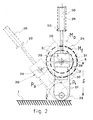
- Figures 1 and 2 show, in schematic form, respectively in front and side view, an embodiment of a device for forming tube portions or the like according to the invention.
- the object of the invention comprises "at least one" element having a given function
- the described embodiment may include several of these elements.
- FIGS. 1 and 2 represent an advantageous embodiment of a device for forming tube portions T 1 , T 2 , ..., T n , T n + 1 , ... or the like successively. one after the other.
- the device comprises a base 1 such as a chassis or the like, two forming jaws 2, 3 to define a housing 4 in which each portion of tube T 1 , T 2 , ..., T n is capable of being formed, this housing being defined along a first axis 6, and means shown diagrammatically 5 for controlling the movement of the two jaws 2, 3 relative to each other and relative to the base 1 so as to obtain either the opening of the housing 4 or its closure.
- the opening and closing of the housing can be obtained by rotation and / or translation of the two jaws.
- FIG. 2 the position of the jaws when the housing is open is represented in fine broken lines and designated by the reference M o while their position when the housing is closed is represented in thick broken lines and designated by the reference M f .
- the jaws 2 and 3 are shown diagrammatically in the closed position M f .
- the device also comprises means 20 for successively positioning each portion of tube T n in the housing 4 when it is open, and means 10 for controlling the forming of each portion of tube when it is placed in the housing and when the latter is in its closed position.
- the means 20 for positioning each portion of tube in the housing 4 when it is open comprise a base 21, means 22 for moving this base 21 in rotation around a second axis 23 relative to the base 1, by a determined angle ⁇ so that the base can take at least two first and second determined positions P 1 , P 2 respectively represented in solid lines and in broken lines in FIG. 2.
- This second axis 23 is further defined by so that it is parallel to the first axis 6 and located at a non-zero distance ⁇ from this first axis 6.
- They also include a head 24, at least two sleeves 25, 26, as illustrated in the two figures, each capable of carrying a portion of tube T n , means 27, 28, like lugs or the like, for securing these two sleeves with the head 24 so that the two sleeves 25, 26 are respectively located on two third 29 and fourth 30 axes competing at a point of competition 31 which remains constantly located at a distance from the second axis 23 equal to ⁇ and outside the housing 4 whatever the position of the base as described below.
- the device comprises two sleeves, but it could be conceivable that it has more than two, regularly angularly distributed around the head 24. However, if this realization is theoretically possible, it does not have enough advantages in practice.
- These means 20 further comprise means 32 for mounting the head 24 in rotation relative to the base 21 around a fifth axis 33 defined on the bisector of the angle ⁇ and so, firstly that this fifth axis 33 forms, with the direction of the second axis 23, an angle equal to ⁇ / 2, the second, third, fourth and fifth axes 23, 29, 30, 33 being coplanar, and on the other hand that the head 24 is driven in the same rotation as that of the base 4 when the latter passes from one of its two positions P 1 , P 2 to the other. It is further specified that the first position P 1 of the base is defined so that the point of competition 31 is located on the first axis 6.
- the means 32 for mounting the head 24 in rotation relative to the base 21 are formed, as more particularly illustrated in FIG. 1, by a motor 40 comprising a stator 41 and a rotor 42, the stator being secured to the base 21 and the head 24 secured to the rotor 42, the stator 41 being secured to the base 21 so that the axis of the rotor 42 is confused with the bisector of the angle ⁇ .
- these means 20 also include means 34 for controlling step by step the rotation of the head 24 relative to the base 21, each step having a value of 180 ° when the number of sleeves is equal to two as in the mode illustrated in Figures 1 and 2, which is in fact the preferred embodiment which gives the best results taking into account the size of the device, the cost of its manufacture and the speed of production of the portions of tube T n with this device.
- These means 34 are advantageously constituted by means electric known in themselves for controlling the motor 40 defined above. These electrical means are capable of issuing successive orders, each order applied to the motor input controlling the rotation of the rotor by an angle of 180 °.
- the device includes means for plugging a portion of tube T n onto one of the two sleeves 25, 26 when it is outside the housing 4 when the other is located in the housing and means to grasp and remove a portion of tube formed T n fitted on a sleeve 25, 26 when the latter has left the housing 4 by passing the base 21 from its first position P 1 to its second position P 2 .
- the angle ⁇ is equal to 90 degrees, as illustrated in Figures 1 and 2.
- the value of the angle ⁇ mentioned above is, in turn, determined so that, in the second position P 2 of the base 21, one of the two sleeves 25, 26 associated with the head 24, when it is located on an axis parallel to the second axis 23, can be outside the space defined between the two jaws 2, 3 when the housing 4 is open, M o .
- the first and second axes 6, 23 are horizontal and located in a vertical plane, the first axis 6 being in additionally located above the second axis 23.
- the axis of the sleeve on which a portion of tube T n to be formed is inserted is vertical and this sleeve is located above the horizontal plane containing the first axis 6.
- the device also comprises means 50 for holding a portion of tube T n on a sleeve 25, 26 after it has been inserted thereon.
- These means 50 illustrated schematically in the figures, may for example be constituted by spring pawls or the like which exert on these tube portions sufficient forces to keep them on the sleeves when the latter are in motion, while allowing to remove the tube portions under the action simply of a tensile force slightly greater than those exerted by these pawls.
- the base 21 is controlled to rotate about the axis 23 and passes from its position P 1 to its position P 2 , FIG. 2.
- the sleeve 25 carrying the portion of tube T n formed comes out of the housing 4.
- the portion of tube T n formed is removed from the sleeve 25 by means of robot tongs or the like.
- the base being always in its second position P 2
- the head 24 is rotated around the axis 33, by an angle of 180 °.
- the sleeve 26 carrying the tube portion T n + 1 to be formed takes the place of the sleeve 25 released from the tube portion T n formed and this sleeve 25 takes the place of the sleeve 26.
- the base 21 returns from its second position P 2 to its first position P 1 .
- the sleeve 26 carrying the new portion of tube T n + 1 to be formed is positioned between the jaws 2, 3, and the sleeve 25 is positioned vertically.
- the jaws 2, 3 pass from their opening position of the housing M o to their closing position M f , the forming of the tube portion T n + 1 by the forming means 10 is controlled, and on the other hand a new portion of tube T n + 2 is brought and inserted on the sleeve 25.
Landscapes
- Engineering & Computer Science (AREA)
- Mechanical Engineering (AREA)
- Bending Of Plates, Rods, And Pipes (AREA)
- Shaping Of Tube Ends By Bending Or Straightening (AREA)
- Forging (AREA)
- Heat Treatment Of Articles (AREA)
- External Artificial Organs (AREA)
- Rigid Pipes And Flexible Pipes (AREA)
- Orthopedics, Nursing, And Contraception (AREA)
Abstract
Description
- un socle,
- deux mâchoires de formage pour définir un logement dans lequel est apte à être formée chaque portion de tube, ledit logement étant défini suivant un premier axe,
- des moyens pour commander le déplacement des deux mâchoires l'une par rapport à l'autre et par rapport au socle de façon à obtenir soit l'ouverture du logement soit sa fermeture,
- des moyens pour positionner chaque portion de tube dans ledit logement quand il est ouvert, et
- des moyens pour commander le formage d'une portion de tube quand elle est placée dans ledit logement et que ce dernier est dans sa position fermée,
- une embase,
- des moyens pour déplacer ladite embase en rotation autour d'un deuxième axe par rapport audit socle, d'un angle déterminé β de façon que ladite embase puisse prendre au moins deux première et seconde positions déterminées, ce dit deuxième axe étant parallèle au premier axe et situé à une distance non nulle δ de ce premier axe,
- une tête,
- au moins deux manchons aptes chacun à porter une portion de tube,
- des moyens pour solidariser ces deux manchons avec ladite tête de façon que les deux manchons soient respectivement situés sur deux troisième et quatrième axes concourant en un point de concours situé à une distance du deuxième axe égale à δ et en dehors dudit logement, ces deux troisième et quatrième axes faisant entre eux un angle non nul α, les deux manchons étant en outre positionnés de façon symétrique par rapport à la bissectrice de l'angle α,
- des moyens pour monter ladite tête en rotation par rapport à l'embase autour d'un cinquième axe défini sur la bissectrice de l'angle α et de façon, d'une part que ce cinquième axe forme, avec la direction du deuxième axe, un angle égal à α / 2, lesdits deuxième, troisième, quatrième et cinquième axes étant coplanaires, et d'autre part que ladite tête soit entraínée dans la même rotation que celle de l'embase quand cette dernière passe de l'une de ses deux positions à l'autre, la première position étant en outre définie de façon que ledit point de concours soit situé sur le premier axe, et
- des moyens pour commander pas à pas la rotation de la tête par rapport à l'embase, chaque pas ayant une valeur de 180°.
Claims (9)
- Dispositif de formage de portions de tube (T1, T2, ..., Tn, Tn+1) ou analogues successivement l'une après l'autre, comportant :caractérisé par le fait que les moyens (20) pour positionner chaque portion de tube dans ledit logement (4) quand il est ouvert, comportentun socle (1),deux mâchoires de formage (2, 3) pour définir un logement (4) dans lequel est apte à être formée chaque portion de tube (T1, T2, ...), ledit logement étant défini suivant un premier axe (6),des moyens (5) pour commander le déplacement des deux mâchoires (2, 3) l'une par rapport à l'autre et par rapport au socle (1) de façon à obtenir soit l'ouverture du logement (4) soit sa fermeture,des moyens (20) pour positionner chaque portion de tube dans ledit logement (4) quand il est ouvert, etdes moyens (10) pour commander le formage d'une portion de tube (Tn) quand elle est placée dans ledit logement et que ce dernier est dans sa position fermée,une embase (21),des moyens (22) pour déplacer ladite embase (21) en rotation autour d'une deuxième axe (23) par rapport audit socle (1), d'un angle déterminé β de façon que ladite embase puisse prendre au moins deux première et seconde positions déterminées (P1, P2), ce dit deuxième axe (23) étant parallèle au premier axe (6) et situé à une distance non nulle δ de ce premier axe,une tête (24),au moins deux manchons (25, 26) aptes chacun à porter une portion de tube (Tn),des moyens (27, 28) pour solidariser ces deux manchons avec ladite tête (24) de façon que les deux manchons (25, 26) soient respectivement situés sur deux troisième (29) et quatrième (30) axes concourant en un point de concours (31) situé à une distance du deuxième axe (23) égale à δ et en dehors dudit logement (4), ces deux troisième (29) et quatrième (30) axes faisant entre eux un angle non nul α, les deux manchons (25, 26) étant en outre positionnés de façon symétrique par rapport à la bissectrice de l'angle α,des moyens (32) pour monter ladite tête (24) en rotation par rapport à l'embase (21) autour d'un cinquième axe (33) défini sur la bissectrice de l'angle α et de façon, d'une part que ce cinquième axe (33) forme, avec la direction du deuxième axe (23), un angle égal à α / 2, lesdits deuxième, troisième, quatrième et cinquième axes (23, 29, 30, 33) étant coplanaires, et d'autre part que ladite tête soit entraínée dans la même rotation que celle de l'embase (4) quand cette dernière passe de l'une de ses deux positions (P1, P2) à l'autre, la première position (P1) étant en outre définie de façon que ledit point de concours (31) soit situé sur le premier axe (6), etdes moyens (34) pour commander pas à pas la rotation de la tête (24) par rapport à l'embase (21), chaque pas ayant une valeur de 180°.
- Dispositif selon la revendication 1, caractérisé par le fait que la valeur de l'angle β est déterminé de façon que, dans la seconde position (P2) de l'embase, l'un des deux manchons (25, 26) qui sont associés avec ladite tête (24), quand il se situe sur un axe parallèle au deuxième axe (23), puisse être en dehors de l'espace défini entre les deux mâchoires (2, 3) lorsque ledit logement (4) est ouvert.
- Dispositif selon l'une des revendications 1 et 2, caractérisé par le fait que l'angle α est égal à 90 degrés.
- Dispositif selon la revendication 3, dans le cas de son utilisation dans un milieu où règne une force de gravitation, caractérisé par le fait que les premier (6) et deuxième (23) axes sont horizontaux et situés dans un plan vertical, le premier axe (6) étant situé au-dessus du deuxième axe (23).
- Dispositif selon la revendication 4, caractérisé par le fait qu'il comporte des moyens pour enficher une portion de tube (Tn) sur le manchon (25, 26) qui se trouve en dehors du logement (4) quand l'autre est situé dans ledit logement.
- Dispositif selon la revendication 5, caractérisé par le fait que, lors de l'enfichage d'une portion de tube sur un manchon, l'axe de ce manchon est vertical et ce manchon est situé au-dessus du plan horizontal contenant le premier axe (6).
- Dispositif selon l'une des revendications 1 à 6, caractérisé par le fait qu'il comporte des moyens pour saisir et enlever une portion de tube formée (Tn) enfichée sur un manchon (25, 26) lorsque ce dernier est sorti du logement (4) par passage de l'embase (21) de sa première position (P1) à sa seconde position (P2).
- Dispositif selon l'une des revendications 1 à 7, caractérisé par le fait qu'il comporte des moyens (50) pour maintenir une portion de tube (Tn) sur un manchon (25, 26) après qu'elle ait été enfichée sur celui-ci.
- Dispositif selon l'une des revendications 1 à 8, caractérisé par le fait que les moyens (32) pour monter la tête (24) en rotation par rapport à l'embase (21) sont constitués par un moteur (40) comportant un stator (41) et un rotor (42), le stator étant solidaire de ladite embase (21) et la tête (24) solidaire du rotor (42), ledit stator (41) étant solidarisé à l'embase (21) de façon que l'axe du rotor (42) soit confondu avec la bissectrice de l'angle α.
Applications Claiming Priority (2)
| Application Number | Priority Date | Filing Date | Title |
|---|---|---|---|
| FR0115034 | 2001-11-21 | ||
| FR0115034A FR2832333B1 (fr) | 2001-11-21 | 2001-11-21 | Dispositif de formage de portions de tube ou analogues successivement l'une apres l'autre |
Publications (2)
| Publication Number | Publication Date |
|---|---|
| EP1314493A1 true EP1314493A1 (fr) | 2003-05-28 |
| EP1314493B1 EP1314493B1 (fr) | 2007-08-01 |
Family
ID=8869612
Family Applications (1)
| Application Number | Title | Priority Date | Filing Date |
|---|---|---|---|
| EP02292802A Expired - Lifetime EP1314493B1 (fr) | 2001-11-21 | 2002-11-12 | Dispositif de formage de portions de tube ou analogues successivement l'une après l'autre |
Country Status (6)
| Country | Link |
|---|---|
| EP (1) | EP1314493B1 (fr) |
| AT (1) | ATE368539T1 (fr) |
| DE (1) | DE60221483T2 (fr) |
| ES (1) | ES2291428T3 (fr) |
| FR (1) | FR2832333B1 (fr) |
| PT (1) | PT1314493E (fr) |
Citations (4)
| Publication number | Priority date | Publication date | Assignee | Title |
|---|---|---|---|---|
| US4019410A (en) * | 1974-03-08 | 1977-04-26 | Rudolf Staszkiewicz | Rotary support for use in a machine tool |
| US4608747A (en) * | 1982-05-06 | 1986-09-02 | Index-Werke Komm.-Ges. Hahn & Tessky | Multispindle-automatic turret lathe |
| US4739642A (en) * | 1986-11-28 | 1988-04-26 | Tube Fab Of Afton Corp. | Tube forming apparatus |
| DE8912645U1 (de) * | 1989-10-25 | 1991-02-21 | Semmlinger, Werner, 8904 Friedberg | Rohrbiegemaschine für lange, dünne Rohre |
-
2001
- 2001-11-21 FR FR0115034A patent/FR2832333B1/fr not_active Expired - Fee Related
-
2002
- 2002-11-12 DE DE60221483T patent/DE60221483T2/de not_active Expired - Lifetime
- 2002-11-12 AT AT02292802T patent/ATE368539T1/de not_active IP Right Cessation
- 2002-11-12 EP EP02292802A patent/EP1314493B1/fr not_active Expired - Lifetime
- 2002-11-12 ES ES02292802T patent/ES2291428T3/es not_active Expired - Lifetime
- 2002-11-12 PT PT02292802T patent/PT1314493E/pt unknown
Patent Citations (4)
| Publication number | Priority date | Publication date | Assignee | Title |
|---|---|---|---|---|
| US4019410A (en) * | 1974-03-08 | 1977-04-26 | Rudolf Staszkiewicz | Rotary support for use in a machine tool |
| US4608747A (en) * | 1982-05-06 | 1986-09-02 | Index-Werke Komm.-Ges. Hahn & Tessky | Multispindle-automatic turret lathe |
| US4739642A (en) * | 1986-11-28 | 1988-04-26 | Tube Fab Of Afton Corp. | Tube forming apparatus |
| DE8912645U1 (de) * | 1989-10-25 | 1991-02-21 | Semmlinger, Werner, 8904 Friedberg | Rohrbiegemaschine für lange, dünne Rohre |
Also Published As
| Publication number | Publication date |
|---|---|
| ATE368539T1 (de) | 2007-08-15 |
| PT1314493E (pt) | 2007-10-02 |
| FR2832333A1 (fr) | 2003-05-23 |
| FR2832333B1 (fr) | 2004-01-16 |
| ES2291428T3 (es) | 2008-03-01 |
| DE60221483T2 (de) | 2008-04-17 |
| DE60221483D1 (de) | 2007-09-13 |
| EP1314493B1 (fr) | 2007-08-01 |
Similar Documents
| Publication | Publication Date | Title |
|---|---|---|
| EP0500405A1 (fr) | Organe de serrage et de préhension | |
| FR2588785A1 (fr) | Appareil a cintrer pour le formage automatique de tubes | |
| EP0330589A1 (fr) | Dispositif pour le transfert d'articles d'au moins un organe support à au moins un autre organe support | |
| EP0768469A1 (fr) | Dispositif de fixation rapide sur un arbre fileté d'entraînement en rotation | |
| CA2034723A1 (fr) | Machine a cintrer les tubes a deux tetes de cintrage | |
| EP0034688A2 (fr) | Machine à corder les raquettes | |
| EP0388296A1 (fr) | Dispositif d'intervention, notamment pour le contrôle, l'inspection et la maintenance des échangeurs de chaleur | |
| EP1314493B1 (fr) | Dispositif de formage de portions de tube ou analogues successivement l'une après l'autre | |
| EP0393567A1 (fr) | Procédé et dispositif pour le rivetage d'un bandage aux sommets d'ailettes montées sur un rotor | |
| FR2658587A1 (fr) | Installation pour la manutention de chapeaux de bouteilles a gaz, avant et apres le remplissage de ces bouteilles. | |
| WO2021229092A1 (fr) | Dispositif d'interface pour bras rotatif robotisé, procédé de commande, dispositif d'intervention | |
| EP0243943A1 (fr) | Outil automatique de serrage et de desserrage d'une vis d'une connexion a brides entre deux tuyaux | |
| CA2037362C (fr) | Pince de coupe, a faible encombrement, pour fibre optique | |
| EP0082159B1 (fr) | Dispositif pour positionner et inserer des rayons dans les trous d'un moyeu de roue a rayons | |
| EP0114774B1 (fr) | Chargeur-extracteur de pièces à un seul moteur de commande | |
| EP3335824B1 (fr) | Système pour extraire une électrode à souder | |
| EP3088144B1 (fr) | Solution de variation de l'espacement dans un dispositif d'ajustement | |
| FR2522294A1 (fr) | Dispositif de chargement et dechargement de pieces pour une machine-outil telle qu'une machine de tournage | |
| EP4234335B1 (fr) | Véhicule équipé de barres de toit modulables et inviolables | |
| FR2572981A1 (fr) | Dispositif de deplacement et de manipulation d'objets dans l'espace. | |
| WO1980000136A1 (fr) | Procede et dispositif de manutention en fonderie | |
| FR2543871A1 (fr) | Procede pour saisir des objets au moyen d'un bras de prehension et pince de prehension | |
| EP1097756A1 (fr) | Machine à former des extrémités de tubes, et dispositif de formage comportant deux desdites machines à former | |
| FR2713973A1 (fr) | Dispositif pour nettoyer l'intérieur d'une lingotière. | |
| FR2520709A1 (fr) | Dispositif pour le maintien, le positionnement et l'entrainement d'un support tubulaire lors de l'enroulement d'une matiere en feuille |
Legal Events
| Date | Code | Title | Description |
|---|---|---|---|
| PUAI | Public reference made under article 153(3) epc to a published international application that has entered the european phase |
Free format text: ORIGINAL CODE: 0009012 |
|
| AK | Designated contracting states |
Designated state(s): AT BE BG CH CY CZ DE DK EE ES FI FR GB GR IE IT LI LU MC NL PT SE SK TR |
|
| AX | Request for extension of the european patent |
Extension state: AL LT LV MK RO SI |
|
| 17P | Request for examination filed |
Effective date: 20031110 |
|
| AKX | Designation fees paid |
Designated state(s): AT BE BG CH CY CZ DE DK EE ES FI FR GB GR IE IT LI LU MC NL PT SE SK TR |
|
| GRAP | Despatch of communication of intention to grant a patent |
Free format text: ORIGINAL CODE: EPIDOSNIGR1 |
|
| GRAS | Grant fee paid |
Free format text: ORIGINAL CODE: EPIDOSNIGR3 |
|
| GRAA | (expected) grant |
Free format text: ORIGINAL CODE: 0009210 |
|
| AK | Designated contracting states |
Kind code of ref document: B1 Designated state(s): AT BE BG CH CY CZ DE DK EE ES FI FR GB GR IE IT LI LU MC NL PT SE SK TR |
|
| REG | Reference to a national code |
Ref country code: GB Ref legal event code: FG4D Free format text: NOT ENGLISH |
|
| REG | Reference to a national code |
Ref country code: CH Ref legal event code: EP |
|
| REG | Reference to a national code |
Ref country code: IE Ref legal event code: FG4D Free format text: LANGUAGE OF EP DOCUMENT: FRENCH |
|
| REF | Corresponds to: |
Ref document number: 60221483 Country of ref document: DE Date of ref document: 20070913 Kind code of ref document: P |
|
| REG | Reference to a national code |
Ref country code: PT Ref legal event code: SC4A Free format text: AVAILABILITY OF NATIONAL TRANSLATION Effective date: 20070919 |
|
| GBT | Gb: translation of ep patent filed (gb section 77(6)(a)/1977) |
Effective date: 20070919 |
|
| PG25 | Lapsed in a contracting state [announced via postgrant information from national office to epo] |
Ref country code: NL Free format text: LAPSE BECAUSE OF FAILURE TO SUBMIT A TRANSLATION OF THE DESCRIPTION OR TO PAY THE FEE WITHIN THE PRESCRIBED TIME-LIMIT Effective date: 20070801 Ref country code: BG Free format text: LAPSE BECAUSE OF FAILURE TO SUBMIT A TRANSLATION OF THE DESCRIPTION OR TO PAY THE FEE WITHIN THE PRESCRIBED TIME-LIMIT Effective date: 20071101 Ref country code: FI Free format text: LAPSE BECAUSE OF FAILURE TO SUBMIT A TRANSLATION OF THE DESCRIPTION OR TO PAY THE FEE WITHIN THE PRESCRIBED TIME-LIMIT Effective date: 20070801 |
|
| NLV1 | Nl: lapsed or annulled due to failure to fulfill the requirements of art. 29p and 29m of the patents act | ||
| PG25 | Lapsed in a contracting state [announced via postgrant information from national office to epo] |
Ref country code: AT Free format text: LAPSE BECAUSE OF FAILURE TO SUBMIT A TRANSLATION OF THE DESCRIPTION OR TO PAY THE FEE WITHIN THE PRESCRIBED TIME-LIMIT Effective date: 20070801 |
|
| REG | Reference to a national code |
Ref country code: ES Ref legal event code: FG2A Ref document number: 2291428 Country of ref document: ES Kind code of ref document: T3 |
|
| REG | Reference to a national code |
Ref country code: IE Ref legal event code: FD4D |
|
| PG25 | Lapsed in a contracting state [announced via postgrant information from national office to epo] |
Ref country code: DK Free format text: LAPSE BECAUSE OF FAILURE TO SUBMIT A TRANSLATION OF THE DESCRIPTION OR TO PAY THE FEE WITHIN THE PRESCRIBED TIME-LIMIT Effective date: 20070801 Ref country code: GR Free format text: LAPSE BECAUSE OF FAILURE TO SUBMIT A TRANSLATION OF THE DESCRIPTION OR TO PAY THE FEE WITHIN THE PRESCRIBED TIME-LIMIT Effective date: 20071102 |
|
| PG25 | Lapsed in a contracting state [announced via postgrant information from national office to epo] |
Ref country code: SK Free format text: LAPSE BECAUSE OF FAILURE TO SUBMIT A TRANSLATION OF THE DESCRIPTION OR TO PAY THE FEE WITHIN THE PRESCRIBED TIME-LIMIT Effective date: 20070801 Ref country code: CZ Free format text: LAPSE BECAUSE OF FAILURE TO SUBMIT A TRANSLATION OF THE DESCRIPTION OR TO PAY THE FEE WITHIN THE PRESCRIBED TIME-LIMIT Effective date: 20070801 Ref country code: IE Free format text: LAPSE BECAUSE OF FAILURE TO SUBMIT A TRANSLATION OF THE DESCRIPTION OR TO PAY THE FEE WITHIN THE PRESCRIBED TIME-LIMIT Effective date: 20070801 |
|
| BERE | Be: lapsed |
Owner name: HUMBERT, ROBERT Effective date: 20071130 |
|
| PLBE | No opposition filed within time limit |
Free format text: ORIGINAL CODE: 0009261 |
|
| STAA | Information on the status of an ep patent application or granted ep patent |
Free format text: STATUS: NO OPPOSITION FILED WITHIN TIME LIMIT |
|
| PG25 | Lapsed in a contracting state [announced via postgrant information from national office to epo] |
Ref country code: SE Free format text: LAPSE BECAUSE OF FAILURE TO SUBMIT A TRANSLATION OF THE DESCRIPTION OR TO PAY THE FEE WITHIN THE PRESCRIBED TIME-LIMIT Effective date: 20071101 Ref country code: MC Free format text: LAPSE BECAUSE OF NON-PAYMENT OF DUE FEES Effective date: 20071130 |
|
| 26N | No opposition filed |
Effective date: 20080506 |
|
| PG25 | Lapsed in a contracting state [announced via postgrant information from national office to epo] |
Ref country code: CH Free format text: LAPSE BECAUSE OF NON-PAYMENT OF DUE FEES Effective date: 20071130 Ref country code: LI Free format text: LAPSE BECAUSE OF NON-PAYMENT OF DUE FEES Effective date: 20071130 |
|
| REG | Reference to a national code |
Ref country code: CH Ref legal event code: PL |
|
| PG25 | Lapsed in a contracting state [announced via postgrant information from national office to epo] |
Ref country code: BE Free format text: LAPSE BECAUSE OF NON-PAYMENT OF DUE FEES Effective date: 20071130 |
|
| PG25 | Lapsed in a contracting state [announced via postgrant information from national office to epo] |
Ref country code: EE Free format text: LAPSE BECAUSE OF FAILURE TO SUBMIT A TRANSLATION OF THE DESCRIPTION OR TO PAY THE FEE WITHIN THE PRESCRIBED TIME-LIMIT Effective date: 20070801 |
|
| PG25 | Lapsed in a contracting state [announced via postgrant information from national office to epo] |
Ref country code: CY Free format text: LAPSE BECAUSE OF FAILURE TO SUBMIT A TRANSLATION OF THE DESCRIPTION OR TO PAY THE FEE WITHIN THE PRESCRIBED TIME-LIMIT Effective date: 20070801 |
|
| PG25 | Lapsed in a contracting state [announced via postgrant information from national office to epo] |
Ref country code: LU Free format text: LAPSE BECAUSE OF NON-PAYMENT OF DUE FEES Effective date: 20071112 |
|
| PG25 | Lapsed in a contracting state [announced via postgrant information from national office to epo] |
Ref country code: TR Free format text: LAPSE BECAUSE OF FAILURE TO SUBMIT A TRANSLATION OF THE DESCRIPTION OR TO PAY THE FEE WITHIN THE PRESCRIBED TIME-LIMIT Effective date: 20070801 |
|
| PGFP | Annual fee paid to national office [announced via postgrant information from national office to epo] |
Ref country code: GB Payment date: 20101108 Year of fee payment: 9 Ref country code: IT Payment date: 20101123 Year of fee payment: 9 |
|
| PGFP | Annual fee paid to national office [announced via postgrant information from national office to epo] |
Ref country code: PT Payment date: 20111107 Year of fee payment: 10 Ref country code: ES Payment date: 20111107 Year of fee payment: 10 Ref country code: FR Payment date: 20111208 Year of fee payment: 10 |
|
| PGFP | Annual fee paid to national office [announced via postgrant information from national office to epo] |
Ref country code: DE Payment date: 20120123 Year of fee payment: 10 |
|
| REG | Reference to a national code |
Ref country code: PT Ref legal event code: MM4A Free format text: LAPSE DUE TO NON-PAYMENT OF FEES Effective date: 20130513 |
|
| GBPC | Gb: european patent ceased through non-payment of renewal fee |
Effective date: 20121112 |
|
| REG | Reference to a national code |
Ref country code: FR Ref legal event code: ST Effective date: 20130731 |
|
| PG25 | Lapsed in a contracting state [announced via postgrant information from national office to epo] |
Ref country code: IT Free format text: LAPSE BECAUSE OF NON-PAYMENT OF DUE FEES Effective date: 20121112 Ref country code: PT Free format text: LAPSE BECAUSE OF NON-PAYMENT OF DUE FEES Effective date: 20130513 |
|
| REG | Reference to a national code |
Ref country code: DE Ref legal event code: R119 Ref document number: 60221483 Country of ref document: DE Effective date: 20130601 |
|
| PG25 | Lapsed in a contracting state [announced via postgrant information from national office to epo] |
Ref country code: DE Free format text: LAPSE BECAUSE OF NON-PAYMENT OF DUE FEES Effective date: 20130601 |
|
| PG25 | Lapsed in a contracting state [announced via postgrant information from national office to epo] |
Ref country code: GB Free format text: LAPSE BECAUSE OF NON-PAYMENT OF DUE FEES Effective date: 20121112 Ref country code: FR Free format text: LAPSE BECAUSE OF NON-PAYMENT OF DUE FEES Effective date: 20121130 |
|
| REG | Reference to a national code |
Ref country code: ES Ref legal event code: FD2A Effective date: 20140305 |
|
| PG25 | Lapsed in a contracting state [announced via postgrant information from national office to epo] |
Ref country code: ES Free format text: LAPSE BECAUSE OF NON-PAYMENT OF DUE FEES Effective date: 20121113 |