EP1314589A2 - Heiz- und/oder Klimaanlage - Google Patents
Heiz- und/oder Klimaanlage Download PDFInfo
- Publication number
- EP1314589A2 EP1314589A2 EP02024326A EP02024326A EP1314589A2 EP 1314589 A2 EP1314589 A2 EP 1314589A2 EP 02024326 A EP02024326 A EP 02024326A EP 02024326 A EP02024326 A EP 02024326A EP 1314589 A2 EP1314589 A2 EP 1314589A2
- Authority
- EP
- European Patent Office
- Prior art keywords
- air
- heating
- conditioning system
- fan
- disk
- Prior art date
- Legal status (The legal status is an assumption and is not a legal conclusion. Google has not performed a legal analysis and makes no representation as to the accuracy of the status listed.)
- Withdrawn
Links
Images


Classifications
-
- F—MECHANICAL ENGINEERING; LIGHTING; HEATING; WEAPONS; BLASTING
- F04—POSITIVE - DISPLACEMENT MACHINES FOR LIQUIDS; PUMPS FOR LIQUIDS OR ELASTIC FLUIDS
- F04D—NON-POSITIVE-DISPLACEMENT PUMPS
- F04D17/00—Radial-flow pumps, e.g. centrifugal pumps; Helico-centrifugal pumps
- F04D17/08—Centrifugal pumps
- F04D17/16—Centrifugal pumps for displacing without appreciable compression
- F04D17/161—Shear force pumps
-
- B—PERFORMING OPERATIONS; TRANSPORTING
- B60—VEHICLES IN GENERAL
- B60H—ARRANGEMENTS OF HEATING, COOLING, VENTILATING OR OTHER AIR-TREATING DEVICES SPECIALLY ADAPTED FOR PASSENGER OR GOODS SPACES OF VEHICLES
- B60H1/00—Heating, cooling or ventilating devices
- B60H1/00007—Combined heating, ventilating, or cooling devices
- B60H1/00021—Air flow details of HVAC devices
- B60H1/00028—Constructional lay-out of the devices in the vehicle
-
- B—PERFORMING OPERATIONS; TRANSPORTING
- B60—VEHICLES IN GENERAL
- B60H—ARRANGEMENTS OF HEATING, COOLING, VENTILATING OR OTHER AIR-TREATING DEVICES SPECIALLY ADAPTED FOR PASSENGER OR GOODS SPACES OF VEHICLES
- B60H1/00—Heating, cooling or ventilating devices
- B60H1/00457—Ventilation unit, e.g. combined with a radiator
-
- B—PERFORMING OPERATIONS; TRANSPORTING
- B60—VEHICLES IN GENERAL
- B60H—ARRANGEMENTS OF HEATING, COOLING, VENTILATING OR OTHER AIR-TREATING DEVICES SPECIALLY ADAPTED FOR PASSENGER OR GOODS SPACES OF VEHICLES
- B60H1/00—Heating, cooling or ventilating devices
- B60H1/00007—Combined heating, ventilating, or cooling devices
- B60H1/00207—Combined heating, ventilating, or cooling devices characterised by the position of the HVAC devices with respect to the passenger compartment
- B60H2001/00214—Devices in front of the passenger compartment
Definitions
- the invention relates to a heating and / or air conditioning system the preamble of claim 1.
- heating and / or air conditioning systems have certain Minimum requirements with regard to the amount of air to be delivered and small space.
- a radial fan properties has a small volume high air promotion support, have heating and / or air conditioning a or several radial fans on.
- the invention is based on the object, a heating and / or Air conditioning for a vehicle interior to create the low Requested space and structurally simple is.
- a heating and / or air conditioning is created be that good efficiency in particular having in the air promotion.
- the heating and / or air conditioning has an air conveyor with one or more air handling units. At least an air conveyor is as a so-called disk fan or Disc ventilator formed.
- the disc fan or disc fan has a packet consisting of a plurality of parallel ones Slices on, with a small distance next to each other on a Shaft are arranged and together by a drive motor are driven. It has surprisingly been found that the formation of an air conveyor as Disc fans no disadvantages in terms of construction volume and / or efficiency but brings several benefits.
- the disc ventilator or disc fan is very quiet during operation, so that noise reduction measures are reduced or completely can be omitted. In the normally used radial fan, On the other hand, noise reduction measures are obligatory. Such measures but require additional space and have a significant air resistance, so that Overall, the efficiency is negatively affected.
- the disc fan or disc fan either as centrally aspirating and tangentially abblasendes Air delivery unit or as tangential ansaugendes and tangential Abblasendes air delivery unit may be formed.
- additional measures for air deflection can be omitted, because the disk fan to the required Heilieren is customizable. The required length of the air ducts and the number of lossy turns can thus be reduced become.
- Another advantage is that the conveying direction of the disk fans is switchable. By changing the direction of rotation of the disc pack the direction of the disk fan can be reversed. Thus, the disk fan by simply changing the direction of rotation for venting and / or venting a vehicle interior be used.
- the Disk fan is designed to dry the evaporator.
- the disk fan at Cooling mode deposits condensate on the evaporator, so that it gets wet and after switching off the cooling Moisture with the air flow into the vehicle interior can.
- the disk fan by reversing the conveying direction for drying the evaporator use. The disk fan pulls dry air out of the Vehicle interior and leads them through the evaporator through to the outside, where it is dried.
- the Disk fan or disc fan can be downstream or be arranged upstream of the evaporator.
- the disk fan can also be designed to dry an air filter his.
- Air conditioners often have an air filter to clean up sucked in air. Is the sucked air moist, e.g. in rain or fog, the air filter becomes soaked and it can be harmful in the filter and / or form odoriferous bacteria.
- the air filter can be dried and whose moisture is discharged to the outside, so that a germination of the air filter avoided or at least is inhibited.
- the disk fan or disc fan in addition to the function of air delivery and / or air deflection at least one more function respectively. So can by the heating and / or air conditioning claimed installation space can be further reduced.
- the disk fan as a water separator is trained. Fresh air is from the heating and / or Air conditioning sucked in via a fresh air intake, the in a water box for separating entrained water droplets empties.
- the water box usually has several Air guide elements, which deflect the air and entrained Separate water.
- Such a water box has due the air deflection on a high air resistance and claimed a lot of space.
- the water box can be omitted entirely or at least be made much more compact.
- the disk fans can circulate air recirculation be formed, each disk fan circulating in the form of a closed roller in the vehicle interior circulated.
- the disk fan as a heat exchanger designed for heating and / or cooling by the Disk fan has heated and / or coolable discs.
- the Slices have intimate contact with the air, so that the Resistance of the heat flow from the rotating disks to the air is quite low. Due to the high speed of the Slices gives a good heat transfer between the Slices and the air.
- targeted heating or cooling Single discs of the disk fan can air quickly and efficiently heated or cooled.
- the disk fan is provided form as an air filter for cleaning air by the discs of the disc fans a preferably adsorbent or ionizing coating.
- the visit can e.g. Have activated carbon to adsorb odors or gases.
- FIG. 1 shows a heating and / or air conditioning system 1 for the vehicle interior 4 in a passenger vehicle.
- An air conditioning case 16 is disposed in the engine room of the passenger car and includes an air cleaner 15, an evaporator 12, a heat exchanger 13, and a disk ventilator 2 belonging to an air conveyance apparatus 11, which is also referred to as a disk fan 2.
- the disk fan 2 is disposed in the air conditioning case 16 upstream of the air filter 15, and conveys outside air into the vehicle interior 4, which is sucked into the air conditioning case 16 through a water tank 17.
- the water box 17 separates with the outside air entrained water and has at its lower end to a drainage.
- a Dashboard 41 arranged across the width of the Vehicle interior extends and a driver's footwell or a passenger footwell limited to the top.
- a driver's seat 44 and a co-located passenger seat 44 share the Vehicle interior 4 in a front section with driver and Passenger footwell 42 and a rear section with a Rear footwell 43 on.
- a disk fan 2 of the air conveyor 11 concealed and circulates circulating air in the adjacent driver or passenger footwell 42 in the form of a closed roll around.
- Another disk fan 2 is in the driver's seat or passenger seat 44 installed concealed and circulates circulating air in the rear foot space 43 in the form of a closed Roll around.
- the structure of the disk fans or disk ventilator 2 is in the further figures shown.
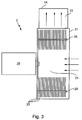
- Figure 2 is a disk fan or Disc ventilator 2 with central intake and tangential Conveying direction in a perspective view and in Figure 3 shown in section.
- the disk fan 2 has a housing 27 on, in which a package of several round slices 23 is rotatably mounted.
- the discs 23 are parallel and arranged at a distance from each other and via screws 25 with each other connected.
- the discs can be replaced by screws also connected by gluing or joining or soldering together his. Between two discs 23 each have an air gap educated.
- the Disc package of the disk fans 2 have about 20 to 100 discs. It has been shown that a slice thickness of 0.2mm to 1mm and a disc distance of 2mm to 8mm, at a disc diameter of 5cm to 30cm are ideal.
- the first disc 23 in the disc pack is a massive one Disc and rotatably connected to a drive motor 26.
- the remaining discs 23 of the package have a concentric Recess, which serves as an air intake opening 21. Tangential to the discs 23 is an air outlet opening 22 in the Housing 27 is arranged.
- the electric drive motor 26 offset the package with the Slices 23 in rotation. Due to the wall friction is the Air is set in rotation and by the centrifugal forces of the central intake opening 21 is conveyed radially outward. It flows out of the housing 27 through the outlet opening 22 out into an adjoining the housing 27 air duct 14th into it.
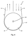
- the construction of the disk ventilator or disk fan 2 with tangential suction opening and tangential discharge opening is shown in a top view in FIG. 4 and in a sectional view in FIG .
- the disk fan 2 has, as in the construction described in Figures 2 and 3, a housing 27 in which a package of a plurality of round discs 23 is rotatably mounted.
- the discs 23 are arranged parallel and spaced from each other and connected by screws 25. Between two disks 23 an air gap is formed in each case.
- the disk pack of the disk fan 2 may have about 20 to 100 disks. It has been shown that a slice thickness of 0.2mm to 1mm and a slice distance of 2mm to 8mm, with a diameter of 5cm to 30cm are ideal.
- discs 23 are formed here solid without recess, arranged on a common shaft 28 and rotatably connected to each other.
- a drive motor 26 drives the shaft 28 and thus sets the package with the discs 23 in rotation.
- the housing 27 has two recesses on one side, which are separated by a partition.
- One of the Recesses is as suction 21 and the other recess designed as a blow-off 22.
- the suction port 21 and the blow-off opening 22 lie in a common plane. This means that the disk fan the direction of the promoted Air flow changes by up to 180 °. There are also versions conceivable in which the disk fan the direction of the promoted Air changes less than 180 °.
- the disks 23 of the disk fan have a coating 24, which is designed to purify the air and active Component contains activated carbon for adsorbing harmful gases.
- Individual discs 23 are formed as Peltier elements, so that they are electrically heated and / or cooled to the Air flow to heat or cool.
- the disk fan can thus advantageous as a water separator and / or dust filter in Vehicle be used.
- the air delivery via the rotating discs 23 of the disk fan 2 is pretty quiet.
- the disk fan 2 can be beneficial without used further measures for noise reduction in the vehicle become.
Landscapes
- Engineering & Computer Science (AREA)
- Mechanical Engineering (AREA)
- Physics & Mathematics (AREA)
- Thermal Sciences (AREA)
- General Engineering & Computer Science (AREA)
- Air-Conditioning For Vehicles (AREA)
Abstract
Description
- Figur 1:
- die Heiz- und/oder Klimaanlage in einem Innenraum eines Kraftfahrzeugs,
- Figur 2:
- die perspektivische Ansicht eines Disk-Fan mit zentraler Luftansaugöffnung und tangentialer Luftabblasöffnung,
- Figur 3:
- eine Schnittdarstellung des Disk-Fan mit zentraler Luftansaugöffnung und tangentialer Luftabblasöffnung,
- Figur 4:
- eine Seitenansicht eines Disk-Fan mit tangentialer Luftansaugöffnung und tangentialer Luftabblasöffnung,
- Figur 5:
- eine Schnittdarstellung des Disk-Fan mit tangentialer Luftansaugöffnung und tangentialer Luftabblasöffnung.
Ein Antriebsmotor 26 treibt die Welle 28 an und versetzt so das Paket mit den Scheiben 23 in Rotation.
Claims (11)
- Heiz- und/oder Klimaanlage für einen Fahrzeuginnenraum, mit einer Luftfördervorrichtung sowie einem Wärmetauscher und vorzugsweise einem Verdampfer zum Konditionieren von Luft, wobei die Luftfördervorrichtung von außen angesaugte Frischluft und/oder aus dem Fahrzeuginnenraum angesaugte Umluft über den Wärmetauscher und/oder den Verdampfer und/oder einen Luftkanal oder mehrere Luftkanäle in das Fahrzeuginnere fördert,
dadurch gekennzeichnet, dass die Luftfördervorrichtung (11) einen Disk-Fan (2) aufweist. - Heiz- und/oder Klimaanlage nach Anspruch 1,
dadurch gekennzeichnet, dass der Disk-Fan (2) als tangential ansaugendes und tangential förderndes Luftförderaggregat ausgebildet ist, so dass seine Lufteinlassöffnung (21) und seine Luftauslassöffnung (22) in einer Ebene liegen. - Heiz- und/oder Klimaanlage nach Anspruch 1,
dadurch gekennzeichnet, dass der Disk-Fan (2) als axial ansaugendes und tangential förderndes Luftförderaggregat ausgebildet ist, so dass seine Lufteinlassöffnung (21) und seine Luftauslassöffnung (22) rechtwinklig zueinander orientiert sind. - Heiz- und/oder Klimaanlage nach einem der Ansprüche 1 oder 2,
dadurch gekennzeichnet, dass der Disk-Fan (2) wahlweise zum Belüften und/oder Entlüften des Fahrzeuginnenraumes (4) einsetzbar ist, indem seine Förderrichtung umschaltbar ist. - Heiz- und/oder Klimaanlage nach einem der Ansprüche 1 bis 4, mit einem Luftfilter zum Reinigen von Luft,
dadurch gekennzeichnet, dass der Disk-Fan (2) zum Trocknen des Verdampfers (12) und/oder des Luftfilters (15) ausgebildet ist, indem der Disk-Fan (2) stromabwärts oder stromaufwärts des Verdampfers (12) und/oder des Luftfilters (15) angeordnet ist, so dass der Disk-Fan (2) bei Förderumkehr den Verdampfer bzw. Luftfilter mit aus dem Fahrzeuginnenraum (4) angesaugter Luft beaufschlagt und an dem Verdampfer (12) bzw. Luftfilter (15) vorhandene Feuchtigkeit nach außen abführt. - Heiz- und/oder Klimaanlage nach einem der Ansprüche 1 bis 5,
dadurch gekennzeichnet, dass der Disk-Fan (2) als Wasserabscheider ausgebildet ist, indem er in der Luft mitgeführte Wassertropfen durch Rotation abtrennt. - Heiz- und/oder Klimaanlage nach einem der Ansprüche 1 bis 6,
dadurch gekennzeichnet, dass der Disk-Fan (2) als Staubfilter ausgebildet ist, indem er in der Luft mitgeführte Staubpartikel durch Rotation abtrennt. - Heiz- und/oder Klimaanlage nach einem der Ansprüche 1 bis 7,
dadurch gekennzeichnet, dass der Disk-Fan (2) als separater Lüfter im Fahrzeuginnenraum (4) ausgebildet ist, der vorzugsweise Umluft in Form einer in sich geschlossenen Walze umwälzt. - Heiz- und/oder Klimaanlage nach einem der Ansprüche 1 bis 8,
dadurch gekennzeichnet, dass die Luftfördervorrichtung mehrere, vorzugsweise zusammenwirkende Disk-Fans (2) aufweist. - Heiz- und/oder Klimaanlage nach einem der Ansprüche 1 bis 9,
dadurch gekennzeichnet, dass der Disk-Fan (2) als Wärmetauscher ausgebildet ist, indem er einen in die Scheiben eingreifenden Ringwärmetauscher oder elektrische leitende Scheiben (23) oder elektrisch beheizbare Scheiben (23) mit elektrisch leitender Beschichtung (24) aufweist. - Heiz- und/oder Klimaanlage nach einem der Ansprüche 1 bis 10,
dadurch gekennzeichnet, dass der Disk-Fan (2) als Luftfilter ausgebildet ist, indem er mit einer Funktionsschicht beschichtete Scheiben (23) aufweist, wobei die Funktionsschicht vorzugsweise adsorbierende und/oder ionisierende Eigenschaften aufweist.
Applications Claiming Priority (2)
| Application Number | Priority Date | Filing Date | Title |
|---|---|---|---|
| DE10157497 | 2001-11-23 | ||
| DE10157497A DE10157497A1 (de) | 2001-11-23 | 2001-11-23 | Heiz- und/oder Klimaanlage |
Publications (2)
| Publication Number | Publication Date |
|---|---|
| EP1314589A2 true EP1314589A2 (de) | 2003-05-28 |
| EP1314589A3 EP1314589A3 (de) | 2004-05-19 |
Family
ID=7706707
Family Applications (1)
| Application Number | Title | Priority Date | Filing Date |
|---|---|---|---|
| EP02024326A Withdrawn EP1314589A3 (de) | 2001-11-23 | 2002-11-02 | Heiz- und/oder Klimaanlage |
Country Status (3)
| Country | Link |
|---|---|
| US (1) | US20030121640A1 (de) |
| EP (1) | EP1314589A3 (de) |
| DE (1) | DE10157497A1 (de) |
Cited By (2)
| Publication number | Priority date | Publication date | Assignee | Title |
|---|---|---|---|---|
| EP2660084A1 (de) * | 2012-04-30 | 2013-11-06 | Weidmann Plastics Technology AG | Wasserkasten für ein Kraftfahrzeug |
| US9139280B2 (en) | 2012-02-08 | 2015-09-22 | Messier-Bugatti-Dowty | Control box |
Families Citing this family (4)
| Publication number | Priority date | Publication date | Assignee | Title |
|---|---|---|---|---|
| DE602004007395T2 (de) * | 2004-11-12 | 2008-03-06 | C.R.F. S.C.P.A. | Klimatisierungsvorrichtung eines Kraftfahrzeuges |
| US9168810B2 (en) * | 2012-10-09 | 2015-10-27 | Delphi Technologies, Inc. | Heating and cooling system for occupants of the rear portion of a vehicle |
| JP2019127248A (ja) * | 2018-01-27 | 2019-08-01 | マツダ株式会社 | 車両用空調装置 |
| JP7346048B2 (ja) * | 2018-05-17 | 2023-09-19 | ハイリマレリジャパン株式会社 | 車両用空調装置 |
Citations (2)
| Publication number | Priority date | Publication date | Assignee | Title |
|---|---|---|---|---|
| DE3738425A1 (de) | 1987-11-12 | 1989-05-24 | Sueddeutsche Kuehler Behr | Klimatisierungseinrichtung, insbesondere fuer ein kraftfahrzeug |
| EP0529099B1 (de) | 1991-03-15 | 1996-07-03 | Toto Ltd. | Mehrschichtiger scheibenlüfter mit schaufeln |
Family Cites Families (18)
| Publication number | Priority date | Publication date | Assignee | Title |
|---|---|---|---|---|
| US2632598A (en) * | 1950-04-05 | 1953-03-24 | Theodore Backer | Centrifugal blower |
| US3473603A (en) * | 1966-01-26 | 1969-10-21 | Hitachi Ltd | Heat exchanger |
| US3722182A (en) * | 1970-05-14 | 1973-03-27 | J Gilbertson | Air purifying and deodorizing device for automobiles |
| JPS56161814U (de) * | 1980-05-06 | 1981-12-02 | ||
| US4658707A (en) * | 1985-09-27 | 1987-04-21 | Hawkins Vernon F | Automatic air purifier for vehicles |
| EP0474929A1 (de) * | 1990-09-11 | 1992-03-18 | International Business Machines Corporation | Laminarströmungsgebläse |
| DE4030144C1 (de) * | 1990-09-24 | 1992-04-23 | Mercedes-Benz Aktiengesellschaft, 7000 Stuttgart, De | |
| DE4030145C1 (de) * | 1990-09-24 | 1992-04-23 | Mercedes-Benz Aktiengesellschaft, 7000 Stuttgart, De | |
| ATE133875T1 (de) * | 1990-11-27 | 1996-02-15 | Toto Ltd | Vorrichtung zur luftbehandlung mit scheiben in mehrlagenstruktur |
| JPH0496516U (de) * | 1991-01-30 | 1992-08-20 | ||
| JPH04353294A (ja) * | 1991-05-30 | 1992-12-08 | Toto Ltd | 多層円板ファン |
| US5192182A (en) * | 1991-09-20 | 1993-03-09 | Possell Clarence R | Substantially noiseless fan |
| JPH05200232A (ja) * | 1992-01-28 | 1993-08-10 | Toto Ltd | 乾式除湿機 |
| JPH05317851A (ja) * | 1992-05-22 | 1993-12-03 | Toto Ltd | 多層円板による液体処理方法 |
| JPH115441A (ja) * | 1997-06-18 | 1999-01-12 | Kansei Corp | 車両用空気清浄器 |
| US5794687A (en) * | 1997-08-04 | 1998-08-18 | International Business Machine Corp. | Forced air cooling apparatus for semiconductor chips |
| DE19814581B4 (de) * | 1998-04-01 | 2007-05-10 | Behr Gmbh & Co. Kg | Klimaanlage für ein Kraftfahrzeug |
| US6598665B2 (en) * | 1999-03-31 | 2003-07-29 | Valeo Climate Control, Inc. | Climate control for vehicle |
-
2001
- 2001-11-23 DE DE10157497A patent/DE10157497A1/de not_active Withdrawn
-
2002
- 2002-11-02 EP EP02024326A patent/EP1314589A3/de not_active Withdrawn
- 2002-11-22 US US10/301,824 patent/US20030121640A1/en not_active Abandoned
Patent Citations (2)
| Publication number | Priority date | Publication date | Assignee | Title |
|---|---|---|---|---|
| DE3738425A1 (de) | 1987-11-12 | 1989-05-24 | Sueddeutsche Kuehler Behr | Klimatisierungseinrichtung, insbesondere fuer ein kraftfahrzeug |
| EP0529099B1 (de) | 1991-03-15 | 1996-07-03 | Toto Ltd. | Mehrschichtiger scheibenlüfter mit schaufeln |
Cited By (4)
| Publication number | Priority date | Publication date | Assignee | Title |
|---|---|---|---|---|
| US9139280B2 (en) | 2012-02-08 | 2015-09-22 | Messier-Bugatti-Dowty | Control box |
| EP2660084A1 (de) * | 2012-04-30 | 2013-11-06 | Weidmann Plastics Technology AG | Wasserkasten für ein Kraftfahrzeug |
| WO2013164260A1 (de) * | 2012-04-30 | 2013-11-07 | Weidmann Plastics Technology Ag | Wasserkasten für ein kraftfahrzeug |
| US9623718B2 (en) | 2012-04-30 | 2017-04-18 | Weidplas Gmbh | Water chamber for a motor vehicle |
Also Published As
| Publication number | Publication date |
|---|---|
| US20030121640A1 (en) | 2003-07-03 |
| EP1314589A3 (de) | 2004-05-19 |
| DE10157497A1 (de) | 2003-06-12 |
Similar Documents
| Publication | Publication Date | Title |
|---|---|---|
| DE19909507C1 (de) | Radialgebläse, insbesondere für Heizungs- und Klimaanlagen | |
| EP0672552B1 (de) | Lufttrocknungsanlage für Kraftfahrzeuge | |
| DE102012201712A1 (de) | Gebläseeinheit | |
| EP1314592A2 (de) | Heiz- und/oder Klimaanlage mit dezentraler Luftfördervorrichtung | |
| DE4002560A1 (de) | Klimageraet | |
| DE10351476B4 (de) | Gargerät zur verbesserten Frischluftzufuhr | |
| EP2418430B1 (de) | Klimatisierungseinrichtung sowie Verfahren zum Konditionieren eines Luftstroms | |
| EP1314589A2 (de) | Heiz- und/oder Klimaanlage | |
| DE60019610T2 (de) | Vorrichtung zur vorfilterung von luft und verfahren zur erzeugung eines sauberen luftstroms | |
| DE29621351U1 (de) | Geschirrspüler mit verbesserter Vorrichtung zum Kondensationstrocknen | |
| EP1589287A1 (de) | Verfahren und eine Vorrichtung zum Be- und/oder Entlüften eines Garofens | |
| DE3738425A1 (de) | Klimatisierungseinrichtung, insbesondere fuer ein kraftfahrzeug | |
| EP0499104B1 (de) | Klimaanlage | |
| DE202008017463U1 (de) | Modulares Lüftungssystem | |
| DE3915932A1 (de) | Heizkoerper zum klimatisieren von raeumen | |
| DE19638535C2 (de) | Be- und Entlüftungsanlage mit Wärmerückgewinnung | |
| DE2013455C3 (de) | Be- und Entlüftungsvorrichtung mit Wärmetauscher | |
| DE202020101127U1 (de) | Klimatisierungseinrichtung sowie Klimatisierungsmodul dafür | |
| CH654398A5 (de) | Geraet zum gleichzeitigen be- und entlueften von raeumen. | |
| DE202007008615U1 (de) | Wärmeaustauscher | |
| DE3720032C2 (de) | ||
| DE4415101A1 (de) | PKW mit einem Heiz-Klimagerät und einem Lufttrockner | |
| EP0890802B1 (de) | Be- und Entlüftungsanlage mit regenerativer Wärmerückgewinnung | |
| DE3831269C3 (de) | Klimatisierungsvorrichtung für einen Reisebus | |
| DE19834131C2 (de) | Fahrzeugkarosserie |
Legal Events
| Date | Code | Title | Description |
|---|---|---|---|
| PUAI | Public reference made under article 153(3) epc to a published international application that has entered the european phase |
Free format text: ORIGINAL CODE: 0009012 |
|
| AK | Designated contracting states |
Designated state(s): AT BE BG CH CY CZ DE DK EE ES FI FR GB GR IE IT LI LU MC NL PT SE SK TR |
|
| AX | Request for extension of the european patent |
Extension state: AL LT LV MK RO SI |
|
| PUAL | Search report despatched |
Free format text: ORIGINAL CODE: 0009013 |
|
| AK | Designated contracting states |
Kind code of ref document: A3 Designated state(s): AT BE BG CH CY CZ DE DK EE ES FI FR GB GR IE IT LI LU MC NL PT SE SK TR |
|
| AX | Request for extension of the european patent |
Extension state: AL LT LV MK RO SI |
|
| RIC1 | Information provided on ipc code assigned before grant |
Ipc: 7F 04D 17/16 B Ipc: 7B 60H 1/00 A |
|
| 17P | Request for examination filed |
Effective date: 20040522 |
|
| 17Q | First examination report despatched |
Effective date: 20040623 |
|
| AKX | Designation fees paid |
Designated state(s): DE FR GB IT |
|
| STAA | Information on the status of an ep patent application or granted ep patent |
Free format text: STATUS: THE APPLICATION HAS BEEN WITHDRAWN |
|
| 18W | Application withdrawn |
Effective date: 20050506 |