EP1495897B2 - Pompe à combustible modulaire avec un collecteur d'évacuation de vapeurs - Google Patents
Pompe à combustible modulaire avec un collecteur d'évacuation de vapeurs Download PDFInfo
- Publication number
- EP1495897B2 EP1495897B2 EP04014888A EP04014888A EP1495897B2 EP 1495897 B2 EP1495897 B2 EP 1495897B2 EP 04014888 A EP04014888 A EP 04014888A EP 04014888 A EP04014888 A EP 04014888A EP 1495897 B2 EP1495897 B2 EP 1495897B2
- Authority
- EP
- European Patent Office
- Prior art keywords
- manifold
- fuel
- vapor
- tank
- vent valve
- Prior art date
- Legal status (The legal status is an assumption and is not a legal conclusion. Google has not performed a legal analysis and makes no representation as to the accuracy of the status listed.)
- Expired - Lifetime
Links
- 239000000446 fuel Substances 0.000 title claims description 69
- 239000002828 fuel tank Substances 0.000 claims description 36
- 238000007789 sealing Methods 0.000 description 3
- 238000011084 recovery Methods 0.000 description 2
- 238000013022 venting Methods 0.000 description 2
- 238000013019 agitation Methods 0.000 description 1
- 238000003915 air pollution Methods 0.000 description 1
- 239000003610 charcoal Substances 0.000 description 1
- 230000003247 decreasing effect Effects 0.000 description 1
- 230000001419 dependent effect Effects 0.000 description 1
- 238000007599 discharging Methods 0.000 description 1
- 239000007788 liquid Substances 0.000 description 1
- 230000000717 retained effect Effects 0.000 description 1
- 238000009423 ventilation Methods 0.000 description 1
Images

Classifications
-
- B—PERFORMING OPERATIONS; TRANSPORTING
- B60—VEHICLES IN GENERAL
- B60K—ARRANGEMENT OR MOUNTING OF PROPULSION UNITS OR OF TRANSMISSIONS IN VEHICLES; ARRANGEMENT OR MOUNTING OF PLURAL DIVERSE PRIME-MOVERS IN VEHICLES; AUXILIARY DRIVES FOR VEHICLES; INSTRUMENTATION OR DASHBOARDS FOR VEHICLES; ARRANGEMENTS IN CONNECTION WITH COOLING, AIR INTAKE, GAS EXHAUST OR FUEL SUPPLY OF PROPULSION UNITS IN VEHICLES
- B60K15/00—Arrangement in connection with fuel supply of combustion engines or other fuel consuming energy converters, e.g. fuel cells; Mounting or construction of fuel tanks
- B60K15/03—Fuel tanks
- B60K15/035—Fuel tanks characterised by venting means
- B60K15/03504—Fuel tanks characterised by venting means adapted to avoid loss of fuel or fuel vapour, e.g. with vapour recovery systems
-
- B—PERFORMING OPERATIONS; TRANSPORTING
- B60—VEHICLES IN GENERAL
- B60K—ARRANGEMENT OR MOUNTING OF PROPULSION UNITS OR OF TRANSMISSIONS IN VEHICLES; ARRANGEMENT OR MOUNTING OF PLURAL DIVERSE PRIME-MOVERS IN VEHICLES; AUXILIARY DRIVES FOR VEHICLES; INSTRUMENTATION OR DASHBOARDS FOR VEHICLES; ARRANGEMENTS IN CONNECTION WITH COOLING, AIR INTAKE, GAS EXHAUST OR FUEL SUPPLY OF PROPULSION UNITS IN VEHICLES
- B60K15/00—Arrangement in connection with fuel supply of combustion engines or other fuel consuming energy converters, e.g. fuel cells; Mounting or construction of fuel tanks
- B60K15/03—Fuel tanks
- B60K2015/03328—Arrangements or special measures related to fuel tanks or fuel handling
- B60K2015/03453—Arrangements or special measures related to fuel tanks or fuel handling for fixing or mounting parts of the fuel tank together
Definitions
- the present invention relates to low-emission fuel tank venting systems. Specifically, the invention relates to a tank-mounted fuel pump module having an integrated manifold for merging multiple vapor sources through a single vapor outlet in the module flange.
- Fuel vapor in vehicle fuel tanks has long been an objective for automobile manufacturers and suppliers of fuel systems components.
- Fuel vapor can be created in the fuel tank by temperature differences between the fuel tank and liquid fuel from a fuel pump, as well as by sloshing and agitation of the fuel tank during normal vehicle operation.
- the vapor collects in various high points within the fuel tank, and is normally released from the fuel tank through one or more vent valves located within the wall of the fuel tank. This prevents pressurization of the tank or the creation of a vacuum therein as a result of fluctuations in fuel volume due especially to changes in temperature or in atmospheric pressure or to the drop in fuel level as the fuel is drawn off.
- EP 1 216 874 A1 discloses a module with integrated vapor manifold comprising a modular flange for mounting to a fuel tank, the flange having a top side, a bottom side, and a manifold for merging fuel vapor received from a plurality of sources within said tank for discharge from said manifold through a single vapor outlet on the top side of the modular flange, at least one source within said tank comprising a remotely located vent valve connected to the manifold through a concealed internal tank vent line.
- a fuel pump module having the features of the preamble of the attached claim 1 is moreover disclosed in EP 1 216 874 A1 . Due to the size restraints of the vehicle, the fuel tank may have a complex shape.
- a fuel pump module as suggested herein has an integrated vapor manifold within the mounting flange for the collection and release of fuel vapor accumulated within a fuel tank.
- the flange combines fuel vapor collected from multiple vapor inlets inside the fuel tank transported to the flange through internal vapor vent lines, and consolidate them into a single outlet through the modular flange.
- the modular flange provides for a means of attaching one or more vent valves directly to the manifold for merging vapors collected proximal to the flange with those of remote sources within the fuel tank.
- the vapors consolidate within the manifold, they are discharged through a single outlet to a remote located canister outside the fuel tank for storage.
- a remote located canister outside the fuel tank for storage.
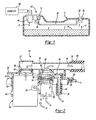
- Figure 1 is a partial-sectional side view of the fuel tank with attached fuel pump module flange and remote vent valve.
- Figure 2 is a partial-sectional side view of the fuel pump module flange and vapor-vent manifold with plural, integral vent valves.
- Figure 3 is a detailed partial-sectional side view of the fuel pump module flange illustrating the junction point of the secondary manifold of Figure 4 .
- Figure 4 is a sectional side view of the secondary manifold having a remote vapor inlet, for attachment of a secondary vent valve to the vapor vent manifold.
- the invention consists of a fuel pump module having a modular flange 20 with an integrated fuel vapor manifold 22, for attachment to an automobile fuel tank 11.
- the flange 20 of the module 10 is attached to an opening in the fuel tank wall 11, and seals the interior volume of the fuel tank from the outside atmosphere.
- the flange 20 comprises an integrated vapor manifold 22 for the collection of fuel vapor 17 from one or more vent valve inlets within the fuel tank11 and merges them into a single outlet port 26 leading to a remote vapor storage canister 60 or other desired location.
- the flange 20 is sealed to the fuel tank 11 by a sealing means 24, but the scope of invention is not intended to be limited by the means in which the flange 20 is attached to the fuel tank wall 11.
- the manifold 22 integrated into the modular flange 20, consists of a manifold chamber 27 having an aperture at one end passing through the flange 20 defining a receptacle 21, for receiving the interface portion 46 of an attached vent valve 40 on the bottom side of the modular flange 20.
- the manifold 22 further defines a secondary vapor inlet 90 wherein the vapor collected from a secondary vent valve 50 or other remote source 14 within the fuel tank 11 enters the manifold 22 and combines with the vapor from the primary vent valve 40.
- the outlet tube 26 attaches to an external vapor tube 62 which carries the fuel vapor to a remote canister 60 for storage, or holding prior to being routed to the engine and burned.
- each valve 40 is typically cylindrical in shape, and has a vapor inlet 42 wherein fuel vapor 17 travels from the interior of the fuel tank 11 into the valve 40 assembly as shown by the arrow 12.
- a check valve which allows the fuel vapor 17 to exit into the manifold 22 while preventing any fuel 19 that may splash onto the vent valve 40 from traveling up into the manifold chamber 27.
- the valve 40 further serves to protect against fuel discharge through the vapor system in the event of inadvertently overfilling the tank 11 during refueling.
- the generally cylindrical interface portion 46 of the upper end of the valve 40 is concisely received by the corresponding valve receptacle 21 located on the manifold 22.
- the interface portion comprises a vapor passage from the valve 40 to the manifold 22, allowing vapor to pass from the valve 40 into the manifold chamber 27.
- a sealing means such as an o-ring 47, is shown implemented in an annular grove on the interface portion 46 of the valve 40 further preventing fuel 19 from passing up into the manifold chamber 27. If the frictional fit between the interface portion 46 of the vent 40, the receptacle 21 on the manifold 22 and the sealing means 47 is tight enough, the valve 40 will be retained securely by the flange 20, wherein further means of attachment may not be necessary.
- a second means of attaching the valve 40 to the flange 20 as shown in Figures 2 and 3 utilizes a snap-fit design, wherein a wedge-shaped vertical tab 44 on the exterior of the vent valve 40 biases the wall 32 of the flange 20 outward upon contact as the valve 40 is inserted upwards into the receptacle 21. Once fully inserted, the tab 44 is received through an aperture 25 on the wall 32 allowing the wall 32 to snap back to its original position locking the vent valve 40 in position.
- This snap-fit means of attachment provides a more secure connection between the valve 40 and the modular flange 20, which may be preferable in fuel vent applications that expose the fuel pump module 10 to more severe jarring.
- a remotely mounted vapor vent valve 30 for the collection of vapor from a portion of a fuel tank 11 distal to the fuel pump modular flange 20 that may be vaporly compartmentalized due to the design of the tank.
- the remote vent valve 30 may be mounted to the tank 11 through a second aperture 15 in the tank wall or by some other means, but is not intended to limit the scope of the invention.
- the vent valve 30 discharges vapor to the internal vent line 34 that carries the vapor 17 from the remote valve 30 to the modular flange 20, where it connects to a manifold adapter 80 illustrated in Figure 4 , which attaches to the modular flange 20 at surface 92.
- the adaptor 80 comprises a vapor chamber 83 defined by walls 82, 84 and 86 which is open on the bottom defining a receptacle for receiving a secondary vent valve 50, attached by similar means as the primary vent valve 40 is attached to the modular flange 20, shown in Figures 2 and 3 . Additional fuel vapor 17 may enter the secondary vent valve 50 through aperture 52, as indicated by the arrow 16.
- the manifold adapter 80 comprises a remote vapor inlet tube 87 leading into the vapor chamber 83, which connects with the internal vent line 34 from the remote vent valve 30 at end 81.
- the adapter 80 in the preferred embodiment is welded to the underside of the manifold 22, in a manner so as to maintain a small gap or passage around the extended outlet tube 88 as shown in Figure 3 .
- the extension of the outlet tube 88 provides for a high point of vapor exit from the manifold adapter 80 into the manifold 22, while the gap allows fuel 19 that may inadvertently bypass the primary vent valve 40 to drain back into the tank 11 instead of undesirably entering the internal vent line 34.
- the combined vapors, now indicated by arrow 18, exit the manifold 22 through the single outlet tube 26 which attaches to the external vapor tube 62, carrying the fuel vapor to canister 60 for storage, prior to being routed to the engine and burned.
- a fuel pump module incorporating fuel vapor collected through one or more vapor vent valves both proximal and distal to the modular flange by an integrated manifold having a single outlet, which significantly reduces the potential sources for fuel vapor emissions into the atmosphere.
Landscapes
- Engineering & Computer Science (AREA)
- Life Sciences & Earth Sciences (AREA)
- Sustainable Development (AREA)
- Sustainable Energy (AREA)
- Chemical & Material Sciences (AREA)
- Combustion & Propulsion (AREA)
- Transportation (AREA)
- Mechanical Engineering (AREA)
- Cooling, Air Intake And Gas Exhaust, And Fuel Tank Arrangements In Propulsion Units (AREA)
- Supplying Secondary Fuel Or The Like To Fuel, Air Or Fuel-Air Mixtures (AREA)
Claims (4)
- Module de pompe à combustible avec collecteur d'évacuation de vapeurs intégré, comprenant:une bride modulaire (20) prévue pour être montée sur un réservoir à combustible (11), la bride comportant une face supérieure, une face inférieure, et un collecteur (22) pour regrouper les vapeurs de combustible reçues d'une pluralité de sources à l'intérieur dudit réservoir afin de les évacuer depuis ledit collecteur à travers un orifice de sortie de vapeurs unique (26) situé sur la face supérieure de la bride modulaire;une soupape de purge principale (40) prevue directement à la face inférieure de la bride modulaire empêchante combustible arrosé sur la soupape de purge principale (40) de marcher dans le collecteur (22) et servante à protéger contre fuit de combustible en cas de surchcharge non voulue de reservoir à combustible (11);au moins une source (14) à l'intérieur dudit réservoir comprenant une soupape de purge (30) distante et reliée au collecteur à travers une ligne de purge dissimulée interne du réservoir (34) ;les vapeurs de combustible collectées depuis ladite soupape de purge distante (30) se mélangeants avec des vapeurs collectées depuis une soupape de purge secondaire (50) avant de pénétrer dans le collecteur (22) ; etladite soupape de purge secondaire (50) étante fixée à proximité du collecteur (22).
- Module de pompe à combustible avec collecteur d'évacuation de vapeurs intégré selon la revendication 1, dans lequel au moins une source à l'intérieur dudit réservoir comprend la soupape de purge principale (40) fixée directement sur la face inférieure du collecteur (22).
- Module de pompe à combustible avec collecteur d'évacuation de vapeurs intégré selon la revendication 1, dans lequel le collecteur comprend des moyens pour empêcher le combustible présent à l'intérieur du collecteur de pénétrer à l'intérieur de la ligne de purge interne au réservoir.
- Module de pompe à combustible avec collecteur d'évacuation de vapeurs intégré (22) selon l'une quelconque des revendications 1 à 3, dans lequel les vapeurs évacuées depuis l'orifice de sortie de vapeurs (26) circulent à travers une conduite de vapeurs externe vers un réceptacle (60) afin d'y être emmagasinées.
Applications Claiming Priority (2)
| Application Number | Priority Date | Filing Date | Title |
|---|---|---|---|
| US616027 | 2003-07-09 | ||
| US10/616,027 US6883500B2 (en) | 2003-07-09 | 2003-07-09 | Fuel pump module with improved vapor vent manifold |
Publications (3)
| Publication Number | Publication Date |
|---|---|
| EP1495897A1 EP1495897A1 (fr) | 2005-01-12 |
| EP1495897B1 EP1495897B1 (fr) | 2006-08-23 |
| EP1495897B2 true EP1495897B2 (fr) | 2009-09-23 |
Family
ID=33452672
Family Applications (1)
| Application Number | Title | Priority Date | Filing Date |
|---|---|---|---|
| EP04014888A Expired - Lifetime EP1495897B2 (fr) | 2003-07-09 | 2004-06-24 | Pompe à combustible modulaire avec un collecteur d'évacuation de vapeurs |
Country Status (4)
| Country | Link |
|---|---|
| US (1) | US6883500B2 (fr) |
| EP (1) | EP1495897B2 (fr) |
| JP (1) | JP2005030381A (fr) |
| DE (1) | DE602004002041T3 (fr) |
Families Citing this family (11)
| Publication number | Priority date | Publication date | Assignee | Title |
|---|---|---|---|---|
| WO2008007352A2 (fr) * | 2006-07-12 | 2008-01-17 | Raval A.C.S. Ltd. | Système de tube de ventilation pour réservoir de carburant |
| EP1967404A1 (fr) * | 2007-03-09 | 2008-09-10 | Delphi Technologies, Inc. | Appareil de purge d'un réservoir de carburant et récupération de vapeur |
| JP5227214B2 (ja) * | 2009-02-19 | 2013-07-03 | 株式会社クボタ | 作業車 |
| US8820298B2 (en) * | 2009-12-07 | 2014-09-02 | Denso International America, Inc. | Passive and semi-active diesel and gasoline fuel module |
| US8469008B2 (en) * | 2009-12-17 | 2013-06-25 | Denso International America, Inc. | Return fuel diffusion device and fuel guide |
| US8485389B2 (en) * | 2011-06-17 | 2013-07-16 | Eaton Corporation | Assembly with vapor vent valve and liquid trap for static leak prevention in vapor control system |
| CN103895498A (zh) * | 2012-12-30 | 2014-07-02 | 芜湖顺荣汽车部件股份有限公司 | 一种汽车燃油箱燃油蒸汽管的布置方法 |
| US10253787B2 (en) | 2013-02-01 | 2019-04-09 | Eaton Intelligent Power Limited | Self-aligning jet pump assembly |
| BR102014010655A2 (pt) * | 2014-05-02 | 2015-12-01 | Aethra Sistemas Automotivos Sa | sistema integrado de ventilação em reservatório de combustível, metálico e com revestimento organo-metálico |
| JP6610580B2 (ja) * | 2017-02-28 | 2019-11-27 | トヨタ自動車株式会社 | 燃料タンクシステム |
| CN109895618A (zh) * | 2017-12-07 | 2019-06-18 | 宝沃汽车(中国)有限公司 | 燃油箱、燃油箱的制造方法以及车辆 |
Citations (5)
| Publication number | Priority date | Publication date | Assignee | Title |
|---|---|---|---|---|
| WO2001021991A1 (fr) † | 1999-09-22 | 2001-03-29 | Stant Manufacturing Inc. | Soupape de reservoir de carburant comprenant un tube d'event interne place dans le reservoir |
| WO2001030601A1 (fr) † | 1999-10-28 | 2001-05-03 | Bayerische Motoren Werke Aktiengesellschaft | Reservoir de carburant pour vehicule |
| EP1314604A1 (fr) † | 2001-11-19 | 2003-05-28 | Delphi Technologies, Inc. | Elément de couverture avec module d'acheminement de carburant |
| CA2415538A1 (fr) † | 2002-01-08 | 2003-07-08 | Eaton Corporation | Controle de ventilation des vapeurs d'un reservoir de carburant |
| EP1320468B1 (fr) † | 2000-09-28 | 2005-11-23 | Eaton Corporation | Montage d'une combinaison de pompe a carburant, transmetteur de niveau et soupape de retenue/mise a l'air libre dans un reservoir a carburant |
Family Cites Families (8)
| Publication number | Priority date | Publication date | Assignee | Title |
|---|---|---|---|---|
| JPH07132740A (ja) * | 1993-11-05 | 1995-05-23 | Toyoda Gosei Co Ltd | 燃料蒸気処理装置 |
| KR100250520B1 (ko) * | 1995-12-11 | 2000-05-01 | 정몽규 | 연료탱크의 가스벤트장치 |
| JP3646217B2 (ja) * | 1999-07-08 | 2005-05-11 | 愛三工業株式会社 | キャニスタモジュール |
| JP3678088B2 (ja) * | 1999-11-26 | 2005-08-03 | 日産自動車株式会社 | 蒸発燃料処理装置 |
| DE20019968U1 (de) | 2000-11-23 | 2001-02-08 | KAUTEX TEXTRON GmbH & Co. KG, 53229 Bonn | Einrichtung zur Kraftstoffversorgung eines Kfz |
| ITTO20001147A1 (it) | 2000-12-11 | 2002-06-11 | Ergom Materie Plastiche Spa | Sistema di recupero dei vapori di carburante da un serbatoio di un autoveicolo e relativo gruppo evaporatore. |
| DE10063414A1 (de) | 2000-12-19 | 2002-06-27 | Kautex Textron Gmbh & Co Kg | Kraftstoffbehälter |
| DE10120542B4 (de) * | 2001-04-26 | 2004-07-15 | Kautex Textron Gmbh & Co. Kg | Kraftstoffbehälter |
-
2003
- 2003-07-09 US US10/616,027 patent/US6883500B2/en not_active Expired - Lifetime
-
2004
- 2004-02-06 JP JP2004031181A patent/JP2005030381A/ja active Pending
- 2004-06-24 EP EP04014888A patent/EP1495897B2/fr not_active Expired - Lifetime
- 2004-06-24 DE DE602004002041T patent/DE602004002041T3/de not_active Expired - Lifetime
Patent Citations (7)
| Publication number | Priority date | Publication date | Assignee | Title |
|---|---|---|---|---|
| WO2001021991A1 (fr) † | 1999-09-22 | 2001-03-29 | Stant Manufacturing Inc. | Soupape de reservoir de carburant comprenant un tube d'event interne place dans le reservoir |
| WO2001030601A1 (fr) † | 1999-10-28 | 2001-05-03 | Bayerische Motoren Werke Aktiengesellschaft | Reservoir de carburant pour vehicule |
| EP1144216B1 (fr) † | 1999-10-28 | 2003-10-08 | Bayerische Motoren Werke Aktiengesellschaft | Reservoir de carburant pour vehicule |
| EP1320468B1 (fr) † | 2000-09-28 | 2005-11-23 | Eaton Corporation | Montage d'une combinaison de pompe a carburant, transmetteur de niveau et soupape de retenue/mise a l'air libre dans un reservoir a carburant |
| EP1314604A1 (fr) † | 2001-11-19 | 2003-05-28 | Delphi Technologies, Inc. | Elément de couverture avec module d'acheminement de carburant |
| CA2415538A1 (fr) † | 2002-01-08 | 2003-07-08 | Eaton Corporation | Controle de ventilation des vapeurs d'un reservoir de carburant |
| EP1325829A2 (fr) † | 2002-01-08 | 2003-07-09 | Eaton Corporation | Contrôle de ventilation des vapeurs de carburant d'un réservoir de carburant |
Also Published As
| Publication number | Publication date |
|---|---|
| DE602004002041D1 (de) | 2006-10-05 |
| EP1495897A1 (fr) | 2005-01-12 |
| DE602004002041T2 (de) | 2007-03-29 |
| US20050005916A1 (en) | 2005-01-13 |
| EP1495897B1 (fr) | 2006-08-23 |
| US6883500B2 (en) | 2005-04-26 |
| DE602004002041T3 (de) | 2010-05-12 |
| JP2005030381A (ja) | 2005-02-03 |
Similar Documents
| Publication | Publication Date | Title |
|---|---|---|
| US6000426A (en) | Fuel system for reducing fuel vapor | |
| ES2288163T3 (es) | Deposito de combustible. | |
| RU2412830C2 (ru) | Отделитель жидкого топлива от паров и топливная система транспортного средства | |
| EP1495897B2 (fr) | Pompe à combustible modulaire avec un collecteur d'évacuation de vapeurs | |
| CN101378930B (zh) | 用于机动车辆的燃料箱 | |
| US7383825B2 (en) | Small engine fuel tank with integrated evaporative controls | |
| US7779820B2 (en) | Liquid separator | |
| EP1810863A1 (fr) | Orifice comprenant un séparateur de membrane | |
| US8596311B2 (en) | Valve assembly for a fuel recirculation line | |
| US6609537B1 (en) | Device for ventilating and venting a fuel tank | |
| EP1600317B1 (fr) | Système de récupération des vapeurs pendant le remplissage | |
| EP1978234A1 (fr) | Structure de fixation de réservoir véhiculaire | |
| US9573461B2 (en) | Filter device and arrangement for ventilating a tank comprising a filter device | |
| US6807952B1 (en) | Fuel tank and fuel flow control device | |
| JP4935456B2 (ja) | キャニスタの吸排気装置およびキャニスタの吸排気用ドレイン容器 | |
| JP2009068350A (ja) | 大気導入部の構造 | |
| US5988145A (en) | Drain pipe of canister | |
| EP1285804A1 (fr) | Séparateur de liquide/vapeur pour réservoir de carburant | |
| US8316899B2 (en) | Fill pocket housing fresh air filter assembly | |
| US20090321444A1 (en) | Fuel container for a motor vehicle | |
| CN114320673A (zh) | 蒸发排放系统 | |
| CN209414021U (zh) | 用于燃油箱的通气阀组件及通气系统和燃油箱系统 | |
| US6755184B2 (en) | Fuel system having a vent structure for communicating with a fuel canister | |
| US20040226439A1 (en) | Integrated PZEV module | |
| CN208184856U (zh) | 碳罐进气防堵装置 |
Legal Events
| Date | Code | Title | Description |
|---|---|---|---|
| PUAI | Public reference made under article 153(3) epc to a published international application that has entered the european phase |
Free format text: ORIGINAL CODE: 0009012 |
|
| AK | Designated contracting states |
Kind code of ref document: A1 Designated state(s): AT BE BG CH CY CZ DE DK EE ES FI FR GB GR HU IE IT LI LU MC NL PL PT RO SE SI SK TR |
|
| AX | Request for extension of the european patent |
Extension state: AL HR LT LV MK |
|
| 17P | Request for examination filed |
Effective date: 20050427 |
|
| AKX | Designation fees paid |
Designated state(s): DE FR GB IT |
|
| GRAP | Despatch of communication of intention to grant a patent |
Free format text: ORIGINAL CODE: EPIDOSNIGR1 |
|
| GRAS | Grant fee paid |
Free format text: ORIGINAL CODE: EPIDOSNIGR3 |
|
| GRAA | (expected) grant |
Free format text: ORIGINAL CODE: 0009210 |
|
| AK | Designated contracting states |
Kind code of ref document: B1 Designated state(s): DE FR GB IT |
|
| PG25 | Lapsed in a contracting state [announced via postgrant information from national office to epo] |
Ref country code: IT Free format text: LAPSE BECAUSE OF FAILURE TO SUBMIT A TRANSLATION OF THE DESCRIPTION OR TO PAY THE FEE WITHIN THE PRESCRIBED TIME-LIMIT;WARNING: LAPSES OF ITALIAN PATENTS WITH EFFECTIVE DATE BEFORE 2007 MAY HAVE OCCURRED AT ANY TIME BEFORE 2007. THE CORRECT EFFECTIVE DATE MAY BE DIFFERENT FROM THE ONE RECORDED. Effective date: 20060823 |
|
| REG | Reference to a national code |
Ref country code: GB Ref legal event code: FG4D |
|
| REF | Corresponds to: |
Ref document number: 602004002041 Country of ref document: DE Date of ref document: 20061005 Kind code of ref document: P |
|
| EN | Fr: translation not filed | ||
| PLBI | Opposition filed |
Free format text: ORIGINAL CODE: 0009260 |
|
| PLAX | Notice of opposition and request to file observation + time limit sent |
Free format text: ORIGINAL CODE: EPIDOSNOBS2 |
|
| 26 | Opposition filed |
Opponent name: SIEMENS AG CT IP SV Effective date: 20070522 Opponent name: VOLKSWAGEN AG Effective date: 20070523 |
|
| PLBB | Reply of patent proprietor to notice(s) of opposition received |
Free format text: ORIGINAL CODE: EPIDOSNOBS3 |
|
| PG25 | Lapsed in a contracting state [announced via postgrant information from national office to epo] |
Ref country code: FR Free format text: LAPSE BECAUSE OF FAILURE TO SUBMIT A TRANSLATION OF THE DESCRIPTION OR TO PAY THE FEE WITHIN THE PRESCRIBED TIME-LIMIT Effective date: 20070511 |
|
| PLAB | Opposition data, opponent's data or that of the opponent's representative modified |
Free format text: ORIGINAL CODE: 0009299OPPO |
|
| PG25 | Lapsed in a contracting state [announced via postgrant information from national office to epo] |
Ref country code: FR Free format text: LAPSE BECAUSE OF FAILURE TO SUBMIT A TRANSLATION OF THE DESCRIPTION OR TO PAY THE FEE WITHIN THE PRESCRIBED TIME-LIMIT Effective date: 20060823 |
|
| PUAH | Patent maintained in amended form |
Free format text: ORIGINAL CODE: 0009272 |
|
| STAA | Information on the status of an ep patent application or granted ep patent |
Free format text: STATUS: PATENT MAINTAINED AS AMENDED |
|
| 27A | Patent maintained in amended form |
Effective date: 20090923 |
|
| AK | Designated contracting states |
Kind code of ref document: B2 Designated state(s): DE FR GB IT |
|
| PLAB | Opposition data, opponent's data or that of the opponent's representative modified |
Free format text: ORIGINAL CODE: 0009299OPPO |
|
| PGFP | Annual fee paid to national office [announced via postgrant information from national office to epo] |
Ref country code: GB Payment date: 20130619 Year of fee payment: 10 Ref country code: DE Payment date: 20130610 Year of fee payment: 10 |
|
| REG | Reference to a national code |
Ref country code: DE Ref legal event code: R119 Ref document number: 602004002041 Country of ref document: DE |
|
| GBPC | Gb: european patent ceased through non-payment of renewal fee |
Effective date: 20140624 |
|
| PG25 | Lapsed in a contracting state [announced via postgrant information from national office to epo] |
Ref country code: DE Free format text: LAPSE BECAUSE OF NON-PAYMENT OF DUE FEES Effective date: 20150101 |
|
| REG | Reference to a national code |
Ref country code: DE Ref legal event code: R119 Ref document number: 602004002041 Country of ref document: DE Effective date: 20150101 |
|
| PG25 | Lapsed in a contracting state [announced via postgrant information from national office to epo] |
Ref country code: GB Free format text: LAPSE BECAUSE OF NON-PAYMENT OF DUE FEES Effective date: 20140624 |