EP1316650A2 - Système hydraulique pour une machine de construction - Google Patents
Système hydraulique pour une machine de construction Download PDFInfo
- Publication number
- EP1316650A2 EP1316650A2 EP02255721A EP02255721A EP1316650A2 EP 1316650 A2 EP1316650 A2 EP 1316650A2 EP 02255721 A EP02255721 A EP 02255721A EP 02255721 A EP02255721 A EP 02255721A EP 1316650 A2 EP1316650 A2 EP 1316650A2
- Authority
- EP
- European Patent Office
- Prior art keywords
- valve
- traveling
- travel
- working
- control valves
- Prior art date
- Legal status (The legal status is an assumption and is not a legal conclusion. Google has not performed a legal analysis and makes no representation as to the accuracy of the status listed.)
- Withdrawn
Links
Images


Classifications
-
- E—FIXED CONSTRUCTIONS
- E02—HYDRAULIC ENGINEERING; FOUNDATIONS; SOIL SHIFTING
- E02F—DREDGING; SOIL-SHIFTING
- E02F9/00—Component parts of dredgers or soil-shifting machines, not restricted to one of the kinds covered by groups E02F3/00 - E02F7/00
- E02F9/20—Drives; Control devices
- E02F9/22—Hydraulic or pneumatic drives
- E02F9/2221—Control of flow rate; Load sensing arrangements
- E02F9/2239—Control of flow rate; Load sensing arrangements using two or more pumps with cross-assistance
-
- E—FIXED CONSTRUCTIONS
- E02—HYDRAULIC ENGINEERING; FOUNDATIONS; SOIL SHIFTING
- E02F—DREDGING; SOIL-SHIFTING
- E02F9/00—Component parts of dredgers or soil-shifting machines, not restricted to one of the kinds covered by groups E02F3/00 - E02F7/00
- E02F9/20—Drives; Control devices
- E02F9/22—Hydraulic or pneumatic drives
- E02F9/2253—Controlling the travelling speed of vehicles, e.g. adjusting travelling speed according to implement loads, control of hydrostatic transmission
-
- E—FIXED CONSTRUCTIONS
- E02—HYDRAULIC ENGINEERING; FOUNDATIONS; SOIL SHIFTING
- E02F—DREDGING; SOIL-SHIFTING
- E02F9/00—Component parts of dredgers or soil-shifting machines, not restricted to one of the kinds covered by groups E02F3/00 - E02F7/00
- E02F9/20—Drives; Control devices
- E02F9/22—Hydraulic or pneumatic drives
- E02F9/2278—Hydraulic circuits
- E02F9/2282—Systems using center bypass type changeover valves
-
- E—FIXED CONSTRUCTIONS
- E02—HYDRAULIC ENGINEERING; FOUNDATIONS; SOIL SHIFTING
- E02F—DREDGING; SOIL-SHIFTING
- E02F9/00—Component parts of dredgers or soil-shifting machines, not restricted to one of the kinds covered by groups E02F3/00 - E02F7/00
- E02F9/20—Drives; Control devices
- E02F9/22—Hydraulic or pneumatic drives
- E02F9/2278—Hydraulic circuits
- E02F9/2292—Systems with two or more pumps
-
- E—FIXED CONSTRUCTIONS
- E02—HYDRAULIC ENGINEERING; FOUNDATIONS; SOIL SHIFTING
- E02F—DREDGING; SOIL-SHIFTING
- E02F9/00—Component parts of dredgers or soil-shifting machines, not restricted to one of the kinds covered by groups E02F3/00 - E02F7/00
- E02F9/20—Drives; Control devices
- E02F9/22—Hydraulic or pneumatic drives
- E02F9/2278—Hydraulic circuits
- E02F9/2296—Systems with a variable displacement pump
Definitions
- the present invention relates to a hydraulic system for a construction machine such as a hydraulic excavator.
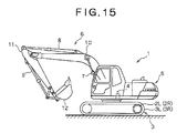
- a hydraulic excavator 1 is provided with a lower travel body 3 which comprises a pair of left and right travel devices 3L, 3R actuated respectively by independent left and right traveling motors 2L, 2R; an upper rotating body 5 mounted on the lower travel body 3 rotatably by a rotating motor 4; and a work machine (work attachments) 6 extended from the upper rotating body 5.
- the work machine 6 is made up of a boom 10, an arm 11, and a bucket 12 which are connected successively to the upper rotating body 5 and which are actuated by a boom cylinder 7, an arm cylinder 8, and a bucket cylinder 9, respectively.
- the motors 2L, 2R, 4 and the cylinders 7, 8, 9 may be termed generically as actuators in this description.
- FIG. 16 A basic configuration of a conventional hydraulic circuit used in this hydraulic excavator 1 is shown in FIG. 16.
- This hydraulic circuit is provided with two variable displacement pumps 20 and 21 serving as pressure oil supply sources and direction control valves 22L, 22R, 23, 24, 25, and 26 which control the supply of pressure oil to the actuators 2L, 2R, 4, and 7 ⁇ 9 in accordance with operations of operating levers (not shown).
- the direction control valves 22L, 22R, and 23 ⁇ 26 are spool valves each having a bleed-off passage 27. Operating positions of those direction control valves are switched with pilot pressures applied to their pilot ports in accordance with operations (direction and quantity of operation) of their respective corresponding operating levers.
- the direction control valves 22L, 22R, and 23 ⁇ 26 are classified into a group G1 consisting of 22R, 24, and 26 and a group G2 consisting of 22L, 23, and 25.
- the direction control valves 22R, 24, and 26 belonging to group G1 are disposed in a center bypass passage 28 successively from an upstream side so that their bleed-off passages 27 are communicated in series when the direction control valves 22R, 24, and 26 are in their neutral positions (their illustrated states).
- the direction control valves 22L, 23, and 25 belonging to group G2 are disposed in a center bypass passage 29 successively from an upstream side.
- the center bypass passages 28 and 29 are connected to respectively to oil tanks 32 through cut-off valves 30 and 31 which can open and close and which are disposed downstream of the direction control valves 26 and 25 located at most-downstream, positions.
- An upstream end of the center bypass passage 28 on the group G1 side is connected to pumps 20 and 21 through a straight-travel valve 33, while an upstream end of the center bypass passage 29 on the group G2 side is connected to a discharge port of the pump 21 on an upstream side of the straight-travel valve 33.
- the pumps 20 and 21 are connected to two inlet ports of the straight-travel valve 33 and the center bypass passage 28 on the group G1 side is connected to one of two outlet ports of the straight-travel valve.
- an oil passage 34 for the work machine is connected to the other outlet port of the straight-travel valve 33, which oil passage 34 is for the supply of pressure oil to the working direction control valves 23 ⁇ 26 located on the downstream side without going through the traveling direction control valves 22R and 22L.
- the straight-travel valve 33 is a two-position control valve having a neutral position X and a position Y.
- An internal passage thereof is formed so that in the neutral position X pressure oil discharged from the pump 20 is fed to only the center bypass passage 28, while pressure oil discharged from the pump 21 is fed to only the center bypass passage 29, and so that upon switching to position Y pressure oil from the pump 21 is fed to both center bypass passages 28 and 29, while pressure oil from the pump 20 is fed to the passage 34 for the working machine.
- Switching operations of the straight-travel valve 33 and the cut-off valves 30, 31 are controlled by a controller (not shown) through an electromagnetic proportional valve for example.
- the straight-travel valve 33 is held in its neutral position X.
- the supply of pressure oil to the actuators 2R, 7, and 9 on the group G1 side and the supply of pressure oil to the actuators 2L, 4, and 8 on the group G2 side are basically performed each independently from the pumps 20 and 21.
- the straight-travel valve 33 is switched from its neutral position X to its position Y.
- pressure oil from the pump 21 is fed to the traveling motors 2R and 2L through the direction control valves 22R and 22L and pressure oil from the pump 20 is fed to the actuators 4 and 7 ⁇ 9 related to works by the work machine 6 through the oil passage 34 for the work machine and further through the direction control valves 23 ⁇ 26 associated with the actuators 4 and 7 ⁇ 9 respectively.
- the pressure oils from the pumps 20 and 21 are used for travel and work respectively.
- the basic pressure oil supply source for operating the traveling motors 2R and 2L is switched from the two pumps 20 and 21 into a single pump 21.
- pressure oil is fed from only the pump 21 to both traveling motors 2R and 2R, the traveling speed of the hydraulic excavator 1 will decrease rapidly.
- a throttle passage 33a which, in the position Y of the straight-travel valve 33, provides communication between a passage for communication of the pumps 21 with the center bypass passage 28 and a passage for communication of the pump 20 with the oil passage 34 for the work machine.
- Pressure oil for work pressure oil on the pump 20 side
- pressure oil for travel pressure oil on the pump 21 side
- the cut-off valve 31 disposed in the center bypass passage 29 is closed by control of a controller (not shown) to prevent pressure relief resulting from flowing of pressure oil from the pump 21 to the oil tank 32 through the center bypass passage 29 on the group G2 side.
- the bleed-off passages 27 in the direction control valves 22R, 22L, and 23 ⁇ 26 are each formed so that the area of opening becomes smaller with an increase in the amount of operation of the associated operating lever (fully closed when the said amount of operation becomes nearly maximum). Therefore, when the amounts of operation of the operating levers associated with the direction control valves 22R, 24, and 26 in group G1 are relatively small, the bleed-off passages 27 in the direction control valves 22R, 24, and 26 are communicated with one another through the center bypass passage 28. This is also true of the direction control valves 22L, 23, and 25 in group G2.
- the pressure oil passage on the pump 20 side and the pressure oil passage on the pump 21 side are in communication with each other through the throttle passage 83a in the straight-travel valve, and this communication may accelerate the aforesaid interference.
- the pressure oil supply source for the traveling motors 2R and 2L switches from two pumps 20 and 21 into a single pump 21, whereby there occurs an inconvenience that a variation in the traveling speed is apt to occur. Such an inconvenience occurs also when travel by the traveling motors 2R and 2L is started under operation of the work machine 6.
- the present invention has been accomplished in view of the above-mentioned background and it is an object of the invention to provide a hydraulic system for a construction machine capable of preventing the occurrence of interference between pressure oil fed to traveling motors and pressure oil fed to working actuators and smoothly performing a work by operation of the working actuators under travel at a stable speed particularly in case of carrying out both travel and work by the working actuators at a time.
- a hydraulic system for a construction machine comprises a first traveling motor and a second traveling motor for actuating a pair of right and left travel devices respectively in the construction machine; a plurality of working actuators; a first pump and a second pump for supply of pressure oil to actuate the traveling motors and the working actuators; a first traveling control valve and a second traveling control valve provided correspondingly to the traveling motors respectively to control the supply of pressure oil to the traveling motors in accordance with operations of operating levers which are associated with the traveling motors respectively; a plurality of working control valves provided correspondingly to the working actuators respectively to control the supply of pressure oil to the working actuators in accordance with operations of operating levers which are associated with the working actuators respectively, the working control valves being classified into a first group including the first traveling control valve and a second group including the second traveling control valve, a first center bypass passage in which the first traveling control valve and the working control valves included in the first group axe disposed successively from an
- the hydraulic system for a construction machine further comprises a straight-travel valve which switches each flow of pressure oil discharged from the first and second pumps so as to supply the pressure oil to the first and second center bypass passages respectively at least when all of the traveling motors and the working actuators are not in operation and to supply pressure oil discharged from one of both pumps to both traveling control valves and further supply pressure oil discharged from the other pump to the working control valves at least in a simultaneous travel/work mode in which the traveling motor and the working actuator corresponding respectively to the traveling control valve and the working control valve belonging to one and same group out of both said groups are operated simultaneously.
- the hydraulic system according to the present invention further comprises a cut-off valve for cutting off the center bypass passage between the traveling control valve and the working control valve belonging to the above same group and corresponding respectively to the traveling motor and the working actuator which are in operation, and an opening valve for opening a downstream side of the bleed-off passage in the traveling control valve to the oil tank, at least in the simultaneous travel/work mode, on a downstream side of the bleed-off passage in each of the traveling control valves.
- the center bypass passage between the bleed-off passage in the traveling control valve corresponding to the traveling motor in operation and the working control valve corresponding to the working actuator in operation on a downstream side of the traveling control valve is cut off by the cut-off valve. Consequently, in the simultaneous travel/work mode, pressure oil fed from the one pump through the straight-travel valve to the traveling motor in operation and pressure oil fed from the other pump through the straight-travel valve to the working actuator in operation, do not interfere with each other through the center bypass passage in which are disposed the traveling control valve and the working control valve corresponding to those traveling motor and working actuator.
- the bleed-off passage in the traveling control valve corresponding to the traveling motor which is in operation opens to the oil tank through the opening valve, so that bleed-off for the traveling motor is effected appropriately making the most of a characteristic of an opening area of the bleed-off passage in the traveling direction control valve, which characteristic is usually a characteristic of the said opening area becoming smaller with an increase in the amount of operation of the operating lever associated with the traveling direction control valve.
- the first mode of the present invention when both travel and work by the working actuators are performed simultaneously, it is possible to prevent interference between pressure oil fed to the traveling motors and pressure oil fed to the working actuators and thereby perform stably the work by operation of the working actuators while allowing the construction machine to travel at a stable speed.
- the opening valve may be fully open in its state of opening.
- the area of its opening may be changed in accordance with the amount of operation of the operating lever corresponding to the traveling motor which is in operation (for example, the opening area may be made smaller with an increase in the amount of operation of the lever).
- the opening valve may be provided for each traveling control valve or may be provided as a common opening valve (a single opening valve) for both traveling control valves.
- the cut-off valve in the simultaneous travel/work mode of only one of both traveling motors being operated, it is preferable to control the cut-off valve so that the center bypass passage corresponding to the other traveling motor is cut off by the cut-off valve. That is, in the simultaneous travel/work mode of only one of both traveling motors being operated, pressure oil is fed from the one pump to both traveling control valves through the straight-travel valve. At this time, the traveling control valve corresponding to the other traveling motor (the traveling motor which is not in operation) is in its neutral position and its bleed-off passage is fully open, but the center bypass passage located downstream of the said traveling control valve is cut off.
- the pressure oil from the one pump is prevented from flowing to the traveling control valve corresponding to the other traveling motor and it becomes possible to supply a sufficient amount of pressure oil to the one traveling motor through the traveling control valve corresponding to the one traveling motor which is in operation.
- the cut-off valve in the center bypass passage located on the traveling control valve side corresponding to the other traveling motor may be closed, but by allowing the cut-off valve to operate as above it is possible to omit such a conventional cut-off valve.
- the cut-off valve and the opening valve may be constituted by separate valves, of course, but both may be constituted by an integrally constructed control valve as unit, whereby it is possible to reduce the number of components of the hydraulic system.
- the cut-off valve and the opening valve may be operated in the above manner only in the foregoing simultaneous travel/work mode, there preferably is provided means which, when all the working actuators are not in operation and when the first or the second traveling motor is in operation, controls the cut-off valve so as to cut off the center bypass passage between the bleed-off passage in the traveling control valve corresponding to the traveling motor which is in operation and the working control valve located on a downstream side thereof, and controls the opening valve so as to open the downstream side of the bleed-off passage in the said traveling control valve to the oil tank.
- each of the traveling control valves is a control valve constructed such that in a neutral position thereof the bleed-off passage thereof opens fully, while in a non-neutral position thereof the said bleed-off passage closes fully, and there are provided an opening valve which, at least when the first or the second traveling motor is in operation, causes an oil passage to open to the oil tank, the said oil passage being located between the traveling control valve associated with the traveling motor which is in operation and the pump for the supply of oil pressure to the said traveling control valve, and means for controlling the area of opening of the opening valve so as to become smaller with an increase in the amount of operation of an operating lever associated with the traveling motor which is in operation.
- the bleed-off passage in the traveling control valve corresponding to the traveling motor which is in operation is kept fully closed, so that the center bypass passage corresponding to the said traveling control valve is cut off by the same traveling control valve.
- the second mode of the present invention when both travel and work by the working actuators are done simultaneously, it is possible to prevent interference between the pressure oil fed to the associated traveling motor and working actuator respectively and carry out the work by operation of the working actuator smoothly while allowing the construction machine to travel at a stable speed.
- the cut-off valve in the center bypass passage having a traveling control valve corresponding to a traveling motor which is not in operation may be closed.
- a valve capable of being opened and closed is disposed in each center bypass passage on the downstream side of each traveling control valve and is allowed to operated in the same manner as the aforesaid cut-off valve.
- the straight-travel valve is a control valve having a first operating position for providing pressure oils from the first and second pumps independently and respectively to the first and second traveling control valves, a second operating position for providing pressure oil from one of both pumps to only both traveling control valves and providing pressure oil from the other pump to only the plural working control valves, and a third operating position for providing communication through a throttle valve between an oil passage communicating with both traveling control valves in the second operating position and an oil passage communicating with the working control valves in the second operating position, and there is provided means which, at least in the simultaneous travel/work mode, controls the straight-travel valve to the second operating position when the amount of operation of an operating lever associated with the traveling motor which is in operation is not larger than a predetermined amount, while when the amount of operation of the operating lever exceeds the predetermined amount, makes control to switch the position of the straight-travel valve to the third operating position from the second operating position.
- the straight-travel valve in the simultaneous travel/work mode, is controlled to the second operating position when the amount of operation of the operating lever associated with the traveling motor which is in operation is not larger than the predetermined amount, that is, when the said amount of operation is relatively small, so that the pressure oils from one and the other pumps are fed each independently to the traveling motor and the working actuator which axe in operation.
- the pressure oils from both pumps are sure to be prevented from interference. Consequently, the work by operation of working actuators can be done smoothly while allowing the construction machine to travel stably at a relatively low speed.
- the means which, when the first or the second traveling motor is in operation with all of the working actuators stopped, controls the position of the straight-travel valve to the second operating position when the amount of operation of the operating lever associated with the traveling motor which is in operation is not larger than the foregoing predetermined amount, while when the amount of operation of the operating lever exceeds the predetermined amount, makes control to switch the position of the straight-travel valve from the second to the first operating position.
- the position of the straight-travel valve is controlled to the second operating position. Therefore, even if the working actuators are started to operate in this state, the straight-travel valve is held in the second operating position. Thus, even if the working actuators are started to operate during travel at a relatively low speed, there is no fear that the flow of pressure oil may suddenly change transitionally. As a result, the operating speed of the traveling motor can be kept stable.
- the position of the straight-travel valve is switched to the first operating position, thus permitting the supply of pressure oils from both pumps independently to the traveling control valves. Consequently, each traveling motor can be operated at a sufficiently high speed. If the operation of the working actuators is started in this state, the position of the straight-travel valve is switched to the third operating position, so there is no fear of a sudden decrease in the amount of pressure oil fed to the traveling motor which is in operation, whereby a sudden decrease in the traveling speed of the construction machine is prevented.
- means which holds the straight-travel valve in the second operating position by a predetermined operation at least in the simultaneous travel/work mode.
- the straight-travel valve when the driver of the construction machine performs a predetermined operation (e.g., operates a switch or performs a voice input operation), the straight-travel valve is held in the second operating position even if the amount of operation of the operating lever associated with the traveling motor in operation becomes large in excess of the predetermined amount.
- the amount of operation of the operating lever associated with the traveling motor in operation need not be maintained at a value of not larger than the predetermined amount. That is, by a relatively rough operation of the operating lever, the operating position of the straight-travel valve can be held in the second operating position which permits positive avoidance of the aforesaid interference.
- the work by working actuators can be done while the construction machine is allowed to travel easily at a stable speed by operation of the traveling motor.
- means which, at least in the simultaneous travel/work mode, adjusts the discharge rate of the pump for the supply of pressure oil to the traveling motor in operation in accordance with the amount of operation of the operating lever associated with the traveling motor, and means which sets, for the means of adjusting the discharge rate of the pump, a characteristic of a change in the discharge rate based on a change in the amount of operation of the operating lever variably by a predetermined operation.
- the discharge rate in the pump for the supply of pressure oil to the traveling motor in operation which discharge rate is proportional to the amount of operation of the operating lever associated with the traveling motor, can be adjusted to a flow rate which the driver desires. Consequently, for example, the operating speed of the traveling motor can be limited to a low speed by keeping the discharge rate low.
- the work by operation of the working actuators can be done while maintaining the traveling speed of the construction machine by the traveling motor at a low speed stably and easily.
- the first mode of the present invention there may be provided means which, at least in the simultaneous travel/work mode, adjusts the area of opening of the opening valve in accordance with the amount of operation of the operating lever associated with the traveling motor in operation, and means which sets, for the means of adjusting the opening area of the opening valve, a characteristic of a change in the opening area in accordance with a change in the amount of operation of the said operating lever variably by a predetermined operation.
- the second mode of the present invention there may be provided means which, at least in the simultaneous travel/work mode, sets a characteristic of a change in the opening area in accordance with a change in the amount of operation of the operating lever variably by a predetermined operation for the means of controlling the opening area of the opening valve.
- the flow rate of bleed-off for the traveling motor in operation and proportional to the amount of operation of the operating lever associated with the traveling motor can be adjusted to a flow rate which the driver desires. Therefore, for example it becomes possible to adjust the flow rate of bleed-off to a rather large flow rate and thereby limit the operating speed of the traveling motor to a low speed.
- the work by the working actuators can be done while keeping the traveling speed of the construction machine by the traveling motor at a low speed stably and easily.
- the oil passage for the supply of pressure oil discharged from the other pump to the working control valves through the straight-travel valve is communicated with an inlet side of the bleed-off passage in each working control valve located on an upstream side of in each of the first and second groups and is also communicated with an inlet side of a meter-in passage in each of the working control valves in the first and second groups.
- FIGS. 1 to 7 A first embodiment of the present invention will be described below with reference to FIGS. 1 to 7.
- This embodiment is related to the hydraulic system in the hydraulic excavator 1 shown in FIG. 15 which has been referred to above.
- the same reference numerals as in FIG. 16 are used also in this embodiment. Further, this embodiment is related to the foregoing first mode of the present invention.
- the hydraulic system of this embodiment is also provided with two variable displacement pumps 20 and 21, direction control valves (traveling control valves) 22R and 22L which are for controlling the supply of pressure oil to right and left traveling motors 2R, 2L in a hydraulic excavator 1, a direction control valve 23 for controlling the supply of pressure oil to a rotating motor 4, direction control valves 24, 25, and 26 for controlling the supply of pressure oil to a boom cylinder 7, an arm cylinder 8, and a bucket cylinder 9, a center bypass passage 28 in which the direction control valves 22R, 24, and 26 belonging to a first group are disposed successively from an upstream side, and a center bypass passage 29 in which the direction control valves 22L, 23, and 25 belonging to a second group are disposed successively from the upstream side.
- the direction control valves 23 to 26 correspond to the working control valves in the present invention.
- the rotating motor 4, boom cylinder 7, arm cylinder 8, and bucket cylinder 9 will sometimes be referred to as working actuator
- Cut-off valves 30 and 31 capable of being opened and closed like those shown in FIG. 16 are disposed downstream of the direction control valves 26 and 25 which are located at most downstream positions in the center bypass passages 28 and 29 respectively.
- the numeral 35 denotes an arm confluence valve for making pressure oil from both pumps 20 and 21 join together and feeding the joined flow to the arm cylinder 8 where required for actuating an arm 11 in the hydraulic excavator 1
- numeral 86 denotes a boom confluence valve for making pressure oil from both pumps 20 and 21 join together and feeding the joined flow to the boom cylinder 7 where required for actuating a boom 10
- numerals 20a and 21a denote regulators for adjusting the discharge rates of the pumps 20 and 21 respectively.
- the hydraulic system of this embodiment is provided with a pair of traveling bypass cut-off valves 37R and 37L possessing the functions of both cut-off valve and opening valve, as well as a straight-travel valve 38 of a different construction from that illustrated in FIG. 16.
- the traveling bypass cut-off valves 37R and 37L are each a three-position change over valve (spool valve) of the same structure having a neutral position A, a position B, and a position C.
- the traveling bypass cut-off valve 37R is disposed in the center bypass passage 28 at a position between the direction control valve 22R for right-hand travel and the direction control valve 24 for boom located downstream of the valve 22R, while the traveling bypass cut-off valve 37L is disposed in the center bypass passage 29 at a position between the direction control valve 22L for left-hand travel and the direction control valve 23 for rotation located downstream of the valve 22L.
- traveling bypass cut-off valve 37R which is located on group G1 side, it causes a bleed-off port of a bleed-off passage 27 in the direction control valve 22R for right-hand travel to communicate with an inlet port of a bleed-off passage 27 in the direction control valve 24 for boom located downstream of the valve 22R.
- the traveling bypass cut-off valve 37R When the traveling bypass cut-off valve 37R is in its position B, it causes the outlet port of the bleed-off passage 27 in the direction control valve 22R for right-hand travel to open to an oil tank 32 through an oil passage 37a formed in the interior of the bypass cut-off valve 37R and at the same time cuts off the flow of pressure oil from the bleed-off passage 27 in the right-hand traveling direction control valve 22R located on the upstream side to the bleed-off passage 27 in the direction control valve 24 for boom located on the downstream side (cuts off the center bypass passage 28 between the direction control valves 22R and 24).
- traveling bypass cut-off valve 37R when the traveling bypass cut-off valve 37R is in its position C, it cuts off the flow of pressure oil from the bleed-off passage 27 in the right-hand traveling direction control valve 22R to the bleed-off passage 27 in the direction control valve 24 for boom located on the downstream side and to the oil tank 32 (closes the center bypass passage 28 extending from the valve 22R to the valve 37R).
- the oil passage 37a which comes into communication with the oil tank 32 at position B of the traveling bypass cut-off valve 37R becomes gradually smaller in the area of its opening as the bypass cut-off valve 37R switches gradually to position C from position B.
- traveling bypass cut-off valve 37R when the traveling bypass cut-off valve 37L, which is located on second group G2 side, is in its neutral position A, it causes an output port of a bleed-off passage 27 in the direction control valve 22L for left-hand travel to communicate with an inlet port of a bleed-off passage in the direction control valve 23 for rotation located downstream of the valve 22L.
- the traveling bypass cut-off valve 37L When the traveling bypass cut-off valve 37L is in its position B, it causes the output port of the bleed-off passage 27 in the direction control valve 22L for left-hand travel to open to the oil tank 32 through an oil passage 37a formed in the interior of the bypass cut-off valve 37L and at the same time cuts off the flow of pressure oil from the bleed-off passage 27 in the left-hand traveling direction control valve 22L located on the upstream side to the bleed-off passage 27 in the direction control valve 23 for rotation located on the downstream side.
- the traveling bypass cut-off valve 37L cuts off the flow of pressure oil from the bleed-off passage 27 in the right-hand traveling direction control valve 22L to the bleed-off passage 27 in the direction control valve 23 for rotation located on the downstream side and to the oil tank 32.
- Electromagnetic proportional reducing valves 39R and 39L are connected respectively to pilot ports of the traveling bypass cut-off valves 37R and 37L.
- the electromagnetic proportional reducing valves 39R and 39L when respective solenoids are energized, produce a pilot pressure of a level proportional to the energizing current from pressure oil of a constant pressure level discharged from a pilot pump (not shown) and provide it to the pilot ports of the traveling bypass cut-off valves 37R and 37L.
- the pilot pressure thus produced becomes larger as the energizing current increases.
- the electromagnetic proportional reducing valves 39R and 39L will be referred to as the right-hand traveling proportional valve 39R and the left-hand traveling proportional valve 39L, respectively.
- the straight-travel valve 38 is a three-position control valve (spool valve) having a neutral position D (first operating position), a position E (second operating position), and a position F (third operating position). Upstream ends of both center bypass passages 28 and 29 and an upstream end of a working oil passage 40 are connected respectively to three outlet ports of the straight-travel valve 38, the working oil passage 40 being for the supply of pressure oil to the direction control valves 23 ⁇ 26 associated with the working actuators 4 and 7 ⁇ 9 without going through both traveling direction control valves 22R and 22L. Further, a discharge port of the pump 21 is connected in communication with one of three inlet ports of the straight-travel valve 38 and a discharge port of the pump 20 is connected in communication with the remaining two inlet ports of the straight-travel valve 38.
- the straight-travel valve 38 in its neutral position D, causes the discharge port of the pump 21 to open to only the center bypass passage 28, causes the discharge port of the pump 20 to open to only the center bypass passage 29, and closes the upstream end of the working oil passage 40.
- the straight-travel valve 38 is in its position E, it causes the discharge port of the pump 21 to open to both center bypass passages 28 and 29 and causes the discharge port of the pump 20 to open to only the working oil passage 40.
- the discharge port of the pump 20 is opened to both center bypass passages 28 and 29 through a throttle passage 88a formed in the interior of the straight-travel valve 38, in addition to opening the discharge port of the pump 21 to both center bypass passages 28 and 29 and opening the discharge port of he pump 20 to the working oil passage 40.
- an electromagnetic proportional reducing valve 41 (hereinafter referred to as the "straight-travel proportional valve 41) of the same construction as the right- and left-hand traveling proportional valves 39R, 39L.
- the working oil passage 40 is provided with a main passage 40a connected to the straight-travel valve 38 and plural branch passages 40b ⁇ 40g branched from the main passage 40a.
- the branch passage 40b is connected to the center bypass passage 28 located between the traveling bypass cut-off valve 37R and the direction control valve 24 for boom on the first group G1 side and is also connected to an inlet port of a meter-in passage in the direction change-valve 24 for boom.
- the branch passage 40c is connected to the center bypass passage 29 located between the traveling bypass cut-off valve 37L and the direction control valve 23 for rotation on the second group G2 side and is also connected to an inlet port of a meter-in passage in the direction control valve 23.
- the branch passages 40d and 40e are connected respectively to an inlet port of a meter-in passage in the direction control valve 26 for bucket and an inlet port of a meter-in passage in the direction control valve 25 for arm. Further, the branch passages 40f and 40g are connected respectively to an inlet port of the arm confluence valve 35 and an inlet port of the boom confluence valve 36.
- an operation quantity detector 44 for detecting operation quantities of operation levers 43 which operate the direction control valves 22R, 22L, and 28 ⁇ 26 respectively through a pilot operation unit 42, a controller 45 which controls the switching operations of the traveling bypass cut-off valves 37R, 37L and the straight-travel valve 38 through the right- and left-hand traveling proportional valves 39R, 39L, and the straight-travel proportional valve 41 and which controls the discharge rates of the pumps 20 and 21 through regulators 20a and 21a, and an operating volume 46 with which the driver of the hydraulic excavator 1 specifies for the driver of the hydraulic excavator 1 a control characteristic for the straight-travel valve 38 by the controller 45 and a flow characteristic of the pumps 20 and 21.
- the controller 45 is constituted by an electronic circuit including a microcomputer, etc. (not shown).
- the pilot operation unit 42 When the operating levers 43 corresponding respectively to the direction control valves 22R, 22L, and 23 ⁇ 26 are operated from their neutral positions, the pilot operation unit 42 produces pilot pressures proportional to the amounts of the operations and outputs the pilot pressures to pilot passages 47a or 47b matching the operated directions of the operating lever 43 out of paired pilot passages 47a and 47b connected respectively to paired pilot ports of the direction control valves 22R, 22L, and 23 ⁇ 26.
- the operation quantity detector 44 detects the pilot pressures in the pilot passages 47a or 47b as pressures which represent the amounts of operation of the operating levers 43, then outputs the detected signals to the controller 45.
- the pilot pressures outputted from the pilot operation unit 42 to the pilot passages 47a and47b become higher with an increase in the amount of operation of the operating levers 43.
- the operating volume 46 is a rotary dial type for example and outputs a signal with a level matching its rotational position to the controller 45.
- the position "OFF" in the figure corresponds to a standard operating position of the operating volume 46.
- the controller 45 executes a processing for judging an operation mode of the hydraulic system with a predetermined cycle time successively in such a manner as shown in a flowchart of FIG. 3.
- the controller 46 acquires detection data on the operating levers 43 from the operation quantity detector 44, that is, acquires detection data on pilot pressures provided to the direction control valves 22R, 22L, and 23 ⁇ 26, (STEP 1). Then, the controller 45 compares the level of a pilot pressure Pi (right-hand travel) which represents the amount of operation of the operating lever 43 associated with the right-hand traveling motor 2R, with a minimum pressure Pis at which a switching operation starts from the neutral position A of the direction control valve 22R (STEP 2).
- a pilot pressure Pi right-hand travel
- the controller 45 further compares the level of a pilot pressure Pi (left-hand travel) which represents the amount of operation of the operating lever 43 associated with the left-hand traveling motor 2L, with the minimum pressure Pis (STEP 5), and if Pi (left-hand travel) ⁇ Pis (with the left-hand traveling motor 2L ON), the controller 45 sets the value of Flag Fb to "1" (STEP 6), while if Pi (left-hand travel) ⁇ Pis (the left-hand traveling motor 2L OFF), the controller sets the value of Flag Fb to "0" (STEP 7).
- a pilot pressure Pi left-hand travel
- the controller 45 compares pilot pressures Pi (work) which represent the amounts of operation of the operating levers 43 associated with the working actuators 4 and 7 ⁇ 9, with the minimum pressure Pis (STEP 8), and if any one of the pilot pressures Pi (work) is Pi (work) ⁇ Pis (when at least one of the working actuators 4 and 7 ⁇ 9 is ON), the controller 45 sets the value of Flag Fc to "1" (STEP 9), while if all the pilot pressures Pi (work) are in a relation of Pi (work) ⁇ Pis (when all the working actuators 4 and 7 ⁇ 9 are OFF), the controller 45 sets the value of Flag Fc to "0" (STEP 10).
- the controller 45 determines energizing currents for the right- and left-hand traveling proportional valves 39R, 39L associated with the traveling bypass cut-off valves 37R and 37L respectively, in the following manner.
- the controller 45 sets energizing currents for the right- and left-hand traveling proportional valves 39R, 39L temporarily.
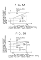
- the energizing current for the right-hand traveling proportional valve 39R becomes a current I1 which switches the position of the traveling bypass cut-off valve 37R from the neutral position held by a predetermined lower-limit current Imin to the position B in an instant when the pilot pressure Pi (right-hand travel) becomes the minimum pressure Pi or higher
- the energizing current in the right-hand traveling proportional valve 39R increases gradually from the current.
- Pie in the figure represents a pilot pressure corresponding to a nearly maximum operation quantity of an operating lever 43.
- the energizing current in the left-hand traveling proportional valve 39L increases from the lower-limit current Imin up to a current I2 (>I1) which switches the traveling bypass cut-off valve 37L to an intermediate position between the positions B and C in an instant when the pilot pressure Pi (right-hand travel rises to a level above the minimum pressure Pis.
- the pilot pressure Pi right-hand travel
- the energizing current in the left-hand traveling proportional valve 39L increases gradually from the current I2 up to the upper-limit current Imax.
- a throttle is formed in the oil passage 37a of the traveling bypass cut-off valve 37L and the opening area of the passage becomes smaller as the energizing current increases. This is also the case with the traveling bypass cut-off valve 37R.
- the controller 45 sets energizing currents for the right- and left-traveling proportional valves 39R, 39L temporarily.
- the energizing current in the left-hand traveling proportional valve 39L with respect to the pilot pressure Pi (left-hand travel) possesses the same characteristic as in the data table of FIG. 4A.
- the energizing current in the right-hand traveling proportional valve 39R with respect to the pilot pressure Pi (left-hand travel) possesses the same characteristic as in the data table of FIG. 4B.
- energizing currents for the right- and left-hand traveling proportional valves 39R, 39L are set temporarily in accordance with pilot pressure Pi (right-hand travel) and energizing currents for the left- and right-hand proportional valves 39L, 39R are set temporarily in accordance with pilot pressure Pi (left-hand travel).
- the controller 45 determines the energizing current of the larger value as the energizing current to be actually fed to the right-hand traveling proportional valve 39R out of the energizing current which has been determined temporarily with reference to the data table of FIG. 4A and in accordance with pilot pressure Pi (right-hand travel) and the energizing current which has been set temporarily with reference to the data table of FIG.
- the controller 45 then supplies the thus-determined energizing current to the right-hand traveling proportional valve 39R.
- the controller 45 determines the energizing current of the larger value as the energizing current to be actually fed to the left-hand traveling proportional valve 39L out of the energizing current which has been set temporarily with reference to the data table of FIG. 4B and in accordance with pilot pressure Pi (right-hand travel) and the energizing current which has been set temporarily with reference to the data table of FIG. 5A and in accordance with pilot pressure Pi (left-hand travel). Then, the controller 45 supplies the thus-determined energizing current to the left-hand traveling proportional valve 39L.
- the controller 45 determines an energizing current for the straight-travel proportional valve 41 in the following manner.
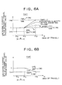
- the energizing current in the straight-travel proportional valve 41 increases gradually from the current I1 up to such a predetermined upper-limit current Imax as holds the straight-travel valve 38 in the position F as the pilot pressure Pi (travel max) increases (as the amount of operation of at least one of the right- and left-hand traveling operating levers 43 increases).
- the energizing current in the straight-travel proportional valve 41 is of a magnitude between the current I1 and the upper-limit current Imax, the straight-travel valve 38 assumes a state intermediate between the positions E and F.
- the dot-dash line graph in FIG. 6A reference will be made later.
- the controller 45 determines an energizing current for the straight-travel proportional valve 41 with reference to a predetermined data table, as shown in FIG. 6B, and in accordance with pilot pressure Pi (travel max). Then, the controller 45 supplies the thus-determined energizing current to the straight-travel proportional valve 41.
- the controller 45 controls the regulator 21a for the pump 21 so that the discharge rate of the pump 21 which serves as a pressure oil supply source for both traveling motors 2R and 2L is varied in accordance with pilot pressures Pi (right-hand travel) and Pi (left-hand travel) related to the operating levers 48 which are associated with the traveling motors 2R and 2L.
- the regulator 21a is controlled in such a manner that, for example as indicated with a solid line in FIG.
- the discharge rate of the pump 21 is increased gradually from a predetermined minimum flow rate Qmin up to a predetermined maximum flow rate Qmax as the total pilot pressure of pilot pressures Pi (right-hand travel) and Pi (left-hand travel), i.e., Pi (right-hand travel) + Pi (left-hand travel), increases above the minimum pressure Pis.
- a predetermined minimum flow rate Qmin up to a predetermined maximum flow rate Qmax as the total pilot pressure of pilot pressures Pi (right-hand travel) and Pi (left-hand travel), i.e., Pi (right-hand travel) + Pi (left-hand travel), increases above the minimum pressure Pis.
- the controller 45 controls the regulator 20a for the pump 20 so that the discharge rate of the pump 20 serving as a pressure oil supply source for the working actuators 4 and 7 ⁇ 9 is varied in accordance with pilot pressures Pi (work) related to the operating levers 43 which are associated with the working actuators 4 and 7 ⁇ 9.
- the regulator 20a for the pump 20 is controlled in accordance with the total sum of pilot pressures (work) corresponding to the working actuators 4 and 7 ⁇ 9 in such a manner that the discharge rate of the pump 20 is increased with an increase in the total sum of the said pilot pressures Pi (work).
- the controller 45 controls the discharge rate of the pump 20 in accordance with the total sum of both pilot pressures Pi (right-hand travel) and Pi (left-hand travel) for example in the same form as the pump 21 (see FIG. 7).
- the controller 45 makes control so that the cut-off valve 30 located most downstream of the center bypass passage 28 is closed through an electromagnetic proportional reducing valve (not shown).
- the controller 45 makes control so that the cut-off valve 31 located most downstream of the center bypass passage 29 is closed through an electromagnetic proportional reducing valve (not shown).
- the above energizing control for the right- and left-hand traveling proportional valves 39R, 39L and the straight-travel proportional valve 41, as well as the above control for the regulators 20a and 21a associated with the pumps 20 and 21, are executed successively by the controller 45 with a cycle time synchronized with the cycle time in the processing of FIG. 3 when the value of Flag Fa or Fb is set to "1" in the processing of FIG. 3, that is, when the traveling motor 2R or 2L is in operation.
- the hydraulic system of this embodiment operates in the following manner.
- the straight-travel valve 38 When the traveling motor 2R or 2L is in operation (including the case where both are ON simultaneously) and when the amount of operation of the operating lever 43 associated with the traveling motor 2R or 2L in operation is relatively small (when pilot pressure Pi travel max) lies in the low-operation range ⁇ ), the straight-travel valve 38 is switched from its neutral position D to its position E and is held in the position E constantly irrespective of whether the working actuators 4 and 7 ⁇ 9 are ON or OFF. In this state, it is only the pump 21 that serves as a pressure oil supply source for the traveling motors 2R and 2L, and at the same time the pump 20 serves as a source for the supply of pressure oil to only the working actuators 4 and 7 ⁇ 9 through the working oil passage 40.
- the traveling bypass cut-off valves 37R and 37L are each switched from the neutral position A to a position close to the position B or C, and the downstream sides of the bleed-off passages 27 in the direction control valves 22R and 22L for travel communicate with the oil tank 32 through the oil passages 37a in the traveling bypass cut-off valves 37R and 37L and are disconnected from the direction control valves 23 ⁇ 26 for work located downstream of the direction control valves 22R and 22L, so that the pressure oil flowing through the bleed-off passages 27 in the direction control valves 22R and 22L does not flow through the direction control valves 23 ⁇ 26 for work.
- the pressure oil fed from the pump 21 to the traveling motor 2R or 2L is not influenced by, for example, a change in pressure of the pressure oil fed from the pump 20 to any of the working actuators 4 and 7 ⁇ 9, nor are conducted switching operations of the straight-travel valve 38 and both bypass cut-off valves 37R and 37L in response to the start of operation of the working actuators 4 and 7 ⁇ 9 during travel of the hydraulic excavator 1.
- the work by the work machine 6 can be done by operation of the working actuators 4 and 7 ⁇ 9 while allowing the hydraulic excavator 1 to travel at a relatively low, stable speed under the operation of traveling motors 2R or 2L.
- the straight-travel valve 38 is switched to the position F side.
- the pump 21 serves as a main pressure oil supply source for the traveling motors 2R and 2L and the pump 20 serves as a main pressure oil supply source for the working actuators 4 and 7 ⁇ 9, but a portion of the pressure oil from the pump 20 is fed to the traveling motors 2R and 2L through the throttle passage 38a at position F of the straight-travel valve 38. Consequently, as in the prior art, it is possible to avoid a sudden deceleration of the hydraulic excavator 1.
- the traveling bypass cut-off valve 37L on the traveling motor 2L side which is OFF is switched to a position close to C rather than position B and the oil passage 37a in the traveling bypass cut-off valve 37L, which provides communication of the center bypass passage 29 located upstream of the traveling bypass cut-off valve 37L with the oil tank 32, tends to close.
- the traveling bypass cut-off valve 37L on the traveling motor 2L side which is OFF is switched to a position close to C rather than position B and the oil passage 37a in the traveling bypass cut-off valve 37L, which provides communication of the center bypass passage 29 located upstream of the traveling bypass cut-off valve 37L with the oil tank 32, tends to close.
- the controller 45 makes control, as indicated with dot-dash lines in the same figure, in such a manner that when the pilot pressure Pi (max of travel) is not lower than the predetermined value Pix (when the amount of operation of the operating level 43 associated with the traveling motor 2R or 2L is relatively large), the energizing current for the straight-travel valve 41 for the pilot pressure Pi (max of travel) is made smaller than in case of the operating volume 46 being operated to "OFF" position, and that the larger the amount of operation of the operating volume 46 to the "ON" position side, the smaller is made the said energizing current.
- the energizing current for the straight-travel proportional valve 41 is maintained at current I1 which holds the straight-travel valve 38 at position E, independently of pilot pressure Pi (travel max), when the pilot pressure Pi (travel max) is not lower than the minimum pressure Pis.
- the controller 45 controls the regulator 21a for the pump 21 so that the discharge rate of the pump 21 for the pilot pressure Pi (right-hand travel) + Pi (left-hand travel) becomes smaller than in case of the operating volume 46 being operated to "OFF" position.
- the controller 45 makes control so that the larger the amount of operation of the operating volume 46, the smaller the discharge rate of the pump 21.
- the traveling speed of the hydraulic excavator 1 is kept to a low speed because the discharge rate of the pump 21 serving as a pressure oil supply source for the traveling motors 2R and 2L is kept to a small value. Consequently, it is possible to easily effect the operation for operating the working actuators 4 and 7 ⁇ 9 while ensuring a stable traveling speed of the hydraulic excavator 1.
- the boom confluence valve 36 is controlled to an open condition by the controller 45 through an electromagnetic proportional reducing valve (not shown) and the cut-off valve 31 is controlled to a closed condition by the controller 45 through an electromagnetic proportional reducing valve (not shown), whereby the pressure oil from both pumps 20 and 21 are joined and fed to the boom cylinder 7.
- the arm confluence valve 35 is controlled to an open condition by the controller 45 through an electromagnetic proportional reducing valve (not shown) and the cut-off valve 30 is controlled to a closed condition by the controller 45 through an electromagnetic proportional reducing valve, whereby the pressure oil from both pumps 20 and 21 are joined and fed to the boom cylinder 7.
- FIGS. 8 and 9 A second embodiment of the present invention will be described below with reference to FIGS. 8 and 9. This embodiment is different only partially in construction from the previous first embodiment, so the same constructional portions as in the first embodiment are identified by the same reference numerals as in the first embodiment and explanations thereof will here be omitted. This embodiment is related to the foregoing first mode of the present invention.
- a hydraulic system of this embodiment is provided with a working oil passage 48 of a different connectional construction from that used in the first embodiment.
- the working oil passage 48 comprises a main passage 48a connected to the straight-travel valve 38 and plural branch passages 48b ⁇ 48g branched from the main passage 48a.
- branch passages 48b ⁇ 48g the branch passages 48b, 48c, 48d, and 48e are connected respectively to inlet ports of meter-in passages in the direction control valve 24 for boom, direction control valve 23 for rotation, direction control valve 26 for bucket, and direction control valve 25 for arm.
- the branch passages 48f and 48g are connected to inlet ports of the arm confluence valve 35 and boom confluence valve 36 respectively.
- An oil passage 49R branched from the center bypass passage 28 at a position between the direction control valve 22R for right-hand travel and the traveling bypass cut-off valve 37R located downstream of the valve 22R is connected into communication with upstream portions of the branch passages 48b, 48d, and 48f located on the first group G1 side, while an oil passage 49L branched from the center bypass passage 29 at a position between the direction control valve 22L for left-hand travel and the traveling bypass cut-off valve 37L located downstream of the valve 22L is connected into communication with upstream portions of the branch passages 38c, 48e, and 48g located on the second group G2 side.
- the hydraulic system of this system is further provided with an unloading valve 50 for work which can open the main passage 48 of the working oil passage 48 to the oil tank 32 and an electromagnetic proportional reducing valve 51 for actuating the unloading valve 50 for work.
- the unloading valve 50 for work is a control valve (spool valve) which can open and close and which can adjust the area of its opening.
- An inlet port of the unloading valve 50 is connected to an oil passage 52 which is branched from the main passage 48a on the upstream side of the branch passages 48b ⁇ 48g of the working oil passage 48, and an outlet port thereof is put in communication with an oil tank 32.
- the unloading valve 50 for work is closed in a neutral state thereof.
- the electromagnetic proportional reducing valve 51 ( “working proportional valve 51" hereinafter) is of the same structure as the proportional valves 39R, 39L, and 41 described in the first embodiment and is connected to a pilot port of the unloading valve 50 for work.
- the cut-off valves 30 and 31 disposed in the center bypass passages 28 and 29 respectively in the first embodiment are not used in this first embodiment.
- the other constructional portions of the hydraulic system of this embodiment are the same as in the first embodiment.
- the hydraulic system of this embodiment illustrated in Fig. 8 for controlling the operation thereof, is provided with the operation quantity detector 44, controller 46, and operating volume 46 which are illustrated in FIG. 2.
- the controller 45 can make an energizing control for the working proportional valve 51 in addition to the proportional valves 39R, 39L, 41 and the regulators 20a, 21a for the pumps 20, 21 described in the first embodiment.
- the controller 45 executes the setting of Flags Fa ⁇ Fd in a successive manner. Then, in accordance with the values of Flags Fa ⁇ Fd the controller 45 makes an energizing control for each of the right- and left-hand traveling proportional valves 39R, 39L, the straight-travel proportional valve 38, and the regulators 20a and 21a for the pumps 20 and 21 in the same way as in the first embodiment, allowing the traveling bypass cut-off valves 37R and 37L and the straight-travel valve 38 to operate and controlling the discharge rate of the pumps 20 and 21 as described in the first embodiment.
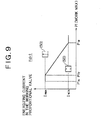
- the controller 45 determines an energizing current for the working proportional valve 51 with reference to a data table built in advance, as in FIG. 9, and in accordance with a maximum pilot pressure Pi (work max) out of pilot pressures Pi (work) which represent the amounts of operation of the operating levers 43 associated with the working actuators 4 and 7 ⁇ 9 respectively.
- the controller 45 then supplies the thus-determined energizing current to the working proportional valve 51, causing the unloading valve 50 for work to operate.
- the energizing current in the working proportional valve 51 is held at the upper-limit current Imax until the pilot pressure Pi (work max) rises to a predetermined pressure Piy which is a little higher than the minimum pressure Pis, and thereafter decreases gradually from the upper-limit current Imax to the lower-limit current Imin with an increase of the pilot pressure Pi (work max) (an increase in the amount of operation of the associated operating lever 43).
- the opening area of the unloading valve 50 for work becomes smaller with a decrease of the energizing current in the working proportional valve 51.
- the controller 45 supplies the upper-limit current Imax to the working proportional valve 51 which current holds the unloading valve 50 for work in a fully open condition,
- the controller 45 supplies the lower-limit current Imin to the working proportional valve 51 which current holds the unloading valve 50 in a closed condition.
- bleed-off for the working actuators 4 and 7 ⁇ 9 in operation is performed through the unloading valve 50 in the simultaneous operation of the traveling motor 2R or 2L and any of the working actuators 4 and 7 ⁇ 9.
- Other operations including the operation performed upon operation of the operating volume 46) and functions and effects are the same as in the first embodiment.
- the controller 45 causes the boom confluence valve 36 to open as in the first embodiment and makes an energizing control for the left-hand traveling proportional valve 39L so as to hold the traveling bypass cut-off valve 37L in position C.
- the controller 45 causes the arm confluence valve 35 to open as in the first embodiment and holds the traveling bypass cut-off valve 37R in position C.
- the cut-off valves 30 and 31 used in the first embodiment are not necessary in this second embodiment.
- FIGS. 10 and 11 A third embodiment of the present invention will now be described with reference to FIGS. 10 and 11.
- This second embodiment is different only partially in construction from the previous second embodiment, so the same constructional portions as in the second embodiment are identified by the same reference numerals as in the second embodiment and explanations thereof will here be omitted.
- This embodiment is related to the foregoing first mode of the present invention.
- traveling bypass cut-off valves 53R and 53L which can merely open and close are disposed in the center bypass passages 28 and 29 respectively.
- the traveling bypass cut-off valves correspond to the cut-off valve in the foregoing first mode of the present invention and are open in their neutral state.
- a right-hand traveling proportional valve 54R and a left-hand proportional valve 54L which are constituted by electromagnetic proportional reducing valves of the same structures as the right- and left-hand traveling proportional valves 39R and 39L, are connected respectively to pilot ports of the traveling bypass cut-off valves 53R and 53L.
- the center bypass passage 28 between the right-hand traveling direction control valve 22R and the traveling bypass cut-off valve 53R located downstream of the valve 22R and the center bypass passage 29 between the left-hand traveling direction control valve 22L and the traveling bypass cut-off valve 53L located downstream of the valve 22L are connected into communication with each other through an oil passage 55.
- the hydraulic system of this embodiment is further provided with an unloading valve 56 for travel which can open the oil passage 55 to an oil tank 32 and an electromagnetic proportional reducing valve 67 for actuating the unloading valve 56.
- the unloading valve 56 for travel is a control valve (spool valve) which can open and close and which can adjust the area of its opening.
- An inlet port of the unloading valve 56 is connected into communication with the oil passage 55 through an oil passage 58 and an outlet port thereof is put in communication with the oil tank 32.
- the unloading valve 56 for travel which is closed in its neutral state, corresponds to the opening valve in the foregoing first mode of the present invention.
- the electromagnetic proportional reducing valve 57 ( " traveling proportional valve 57" hereinafter) is of the same structure as the straight-travel proportional valve 41 and is connected to a pilot port of the unloading valve 56 for travel.
- the controller 45 executes the setting of Flags Fa ⁇ Fd in a successive manner.
- the controller 45 makes an energizing control for each of the straight-travel proportional valve 38, the working proportional valve 51, and the regulators 20a and 21a for the pumps 20 and 21 in the same manner as in the second embodiment, allowing the straight-travel valve 38 and the unloading valve 50 for work to operate and controlling the discharge rate of the pumps 20 and 21 as described in the first embodiment.
- the controller 45 makes control to supply an energizing current (upper-limit current) which holds both traveling bypass cut-off valves 53R and 53L in a closed condition to the right- and left-hand traveling proportional valves 54R, 54L independently of pilot pressures Pi (right-hand travel) (>Pis) and Pi (left-hand travel) (>Pis) which are related to the amount of operation of the operating lever 43 for travel.
- energizing current upper-limit current
- the controller 45 then supplies the thus-determined energizing current to the traveling proportional valve 57, causing the unloading valve 56 for travel to operate.
- the dot-dash line graphs in FIGS. 11A and 11B are concerned with the case where the operating volume 46 is operated to "ON" position. On this regard, a description will be given later. Here it is assumed that the operating volume 46 is operated to "OFF" position.
- the energizing current in the traveling proportional valve 57 is held in the upper-limit current Imax until the pilot pressure Pi (travel max) rises to a predetermined pressure Piz which is higher than the minimum Pis, then decreases gradually from the upper-limit current Imax to the lower-limit current Imin with an increase of the pilot pressure Pi (work max) (an increase in the amount of operation of the operating lever 43 for travel).
- the area of opening of the unloading valve 56 for travel becomes smaller as the energizing current in the traveling proportional valve 57 decreases.
- the traveling bypass cut-off valves 53R, 53L and the unloading valve 56 for travel used in this embodiment fulfill the same function as that of the traveling bypass cut-off valves 37R and 37L used in the first and second embodiments.
- the other constructions and operations than those of the traveling bypass cut-off valves 53R, 53L and the unloading valve 56 for travel are the same as in the second embodiment. Therefore, also in this embodiment there can be attained the same functions and effects as in the second embodiment.
- the controller 46 supplies the traveling proportional valve 57 with such an energizing current as keeps the opening area of the unloading valve 56 for travel at a constant opening area in a relatively high pilot pressure Pi (travel max), as indicated with dot-dash lines in FIGS. 11A and 11B.
- the larger the amount of operation of the operating volume 46 the larger the energizing current in the traveling proportional valve 57.
- the controller 45 causes the boom confluence valve 36 to open in the same manner as in the first embodiment and makes an energizing control for the left-hand traveling proportional valve 54L so as to keep the traveling bypass cut-off valve 53L closed.
- the controller 45 causes the arm confluence valve 35 to open in the same manner as in the first embodiment and holds the traveling bypass cut-off valve 53R in a closed condition.
- the cut-off valves 30 and 31 used in the first embodiment are not necessary.
- the unloading valve 56 for travel is used in common to both traveling motors 2R and 2L
- separate unloading valves for travel may be connected to the downstream sides of the bleed-off passages 27 of the traveling direction control valves 22R and 22L (upstream sides of the traveling bypass cut-off valves 53R and 53L).
- the separate unloading valves may be operated according to pilot pressures Pi (right-hand travel) and Pi (left-hand travel) corresponding respectively to the traveling motors 2R and 2L for example with such a characteristic as shown in FIG. 11A.
- the unloading valve for travel associated with the traveling motor 2R which is in operation is operated according to pilot pressure Pi (right-hand travel) with such a characteristic as shown in FIG. 11A, while the unloading valve for travel associated with the traveling motor 2L which is OFF is held in a closed condition.
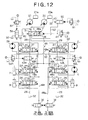
- FIGS. 12 and 13 This embodiment is different only partially in construction from the previous third embodiment, so the same constructional portions as in the third embodiment are identified by the same reference numerals as in the third embodiment and explanations thereof will here be omitted.
- This embodiment is related to the foregoing second mode of the present invention.
- the spool shape of traveling direction control valves 22RR and 22LL and an elastic force characteristic of a return spring are set beforehand so that the bleed-off passages 27 in the direction control passages 22RR and 22LL vary in the area of opening in accordance with pilot pressures Pi (right-hand travel) and Pi (Left-hand travel) which are applied to pilot ports of the valves 22RR and 22LL.
- the bleed-off passages 27 in the direction control valves 22RR and 22LL assume a fully closed state immediately from a fully open state and are thereafter held in the fully closed state independently of an increase of pilot pressures Pi (right-hand travel) and Pi (left-hand travel).
- meter-in passages in the direction control valves 22RR and 22LL become larger in their opening area with an increase of pilot pressures Pi (right-hand travel) and Pi (left-hand travel).
- an unloading valve 56 for travel which corresponds to the opening valve in the foregoing second mode of the present invention, is connected to an oil passage 59 extending from the pump 21 to the straight-travel valve 38, through an oil passage 60 branched from the oil passage 59.
- the other constructional portions than above are just the same as in the previous third embodiment.
- the controller 45 executes the setting of Flags Fa ⁇ Fd in a successive manner, then in accordance with the values of Flags Fa ⁇ Fd the controller 45 makes an energizing control for the straight-travel valve 38, the working proportional valve 51, and the regulators 20a and 21a for the pumps 20 and 21, causing the straight-travel valve 38 and the unloading valve 50 for work to operate, and controls the discharge rate of the pumps 20 and 21.
- energizing current upper-limit current
- the traveling bypass cut-off valve 53R or 53L associated with the traveling motor 2R or 2L which is OFF is closed when only one of the traveling motors 2R and 2L is ON, whereby the pressure oil from the pump 21 flows through the center bypass passage 28 or 29 associated with the traveling motor 2R or 2L which is OFF and what is called pressure relief is prevented thereby.
- the traveling bypass cut-off valves 53R and 53L may be disposed at the positions of the cut-off valves 35 and 36 used in the first embodiment and illustrated in FIG. 1, or the cut-off valves 35 and 36 illustrated in FIG. 1 may be used as the traveling bypass cut-off valves 53R and 53L in this embodiment.
- the straight-travel valve 38 of such a construction as shown in FIGS. 1, 8, 10, and 12 is used in the first to fourth embodiments
- the straight-travel valve used in the present invention is not limited thereto.
- a straight-travel valve of such a construction as shown in FIG. 14A or 14B there may be used a straight-travel valve of such a construction as shown in FIG. 14A or 14B.
- FIGS. 14A and 14B the same functional portions as in the previous embodiments are identified by the same reference numerals as in the previous embodiments.
- the straight-travel valves shown in both figures exhibit the same function as that of the straight-travel valve 38 used in the previous embodiments, and how to operate and control them may also be the same as in the previous embodiments.
- a control characteristic for the pilot pressure Pi (travel max) in the straight-travel valve 38 is changed stepwise according to the amount of operation of the operating volume 46, but there may be adapted a modification in which when the operating volume 46 lies in its "ON" position for example and during operation of the traveling motor 2R or 2L, the straight-travel valve 38 is controlled constantly with such a characteristic as indicated by a dot-dash line "a" in FIG. 6A and is thereby held in its position E.
- the operating volume 46 is used for making the control characteristic of the straight-travel valve 38, etc. variable
- the control characteristic of the straight-travel valve 38, etc. may be rendered variable by operating a two-stage control switch having only two operating positions corresponding to "OFF" and "ON" positions of the operating volume 46 or by driver' s voice indication or the like.
- the working oil passage 48 is constructed in the same manner as in the second embodiment, there may be adapted such a working oil passage 40 as in the first embodiment.
- the unloading valve 50 for work, the working proportional valve 51 and the oil passage 52 used in the fourth embodiment are removed and the unloading valve 56 and the traveling bypass cut-off valves 53R and 53L are controlled in the manner described in the fourth embodiment.
- such cut-off valves 30 and 31 as those used in the first embodiment are disposed in the most downstream portions of the center bypass passages 28 and 29 and may be operated as described in the first embodiment.
Landscapes
- Engineering & Computer Science (AREA)
- Mining & Mineral Resources (AREA)
- Civil Engineering (AREA)
- General Engineering & Computer Science (AREA)
- Structural Engineering (AREA)
- Physics & Mathematics (AREA)
- Fluid Mechanics (AREA)
- Operation Control Of Excavators (AREA)
- Fluid-Pressure Circuits (AREA)
Applications Claiming Priority (2)
| Application Number | Priority Date | Filing Date | Title |
|---|---|---|---|
| JP2001252003 | 2001-08-22 | ||
| JP2001252003A JP3614121B2 (ja) | 2001-08-22 | 2001-08-22 | 建設機械の油圧装置 |
Publications (2)
| Publication Number | Publication Date |
|---|---|
| EP1316650A2 true EP1316650A2 (fr) | 2003-06-04 |
| EP1316650A3 EP1316650A3 (fr) | 2003-07-23 |
Family
ID=19080551
Family Applications (1)
| Application Number | Title | Priority Date | Filing Date |
|---|---|---|---|
| EP02255721A Withdrawn EP1316650A3 (fr) | 2001-08-22 | 2002-08-16 | Système hydraulique pour une machine de construction |
Country Status (3)
| Country | Link |
|---|---|
| US (1) | US6708490B2 (fr) |
| EP (1) | EP1316650A3 (fr) |
| JP (1) | JP3614121B2 (fr) |
Cited By (4)
| Publication number | Priority date | Publication date | Assignee | Title |
|---|---|---|---|---|
| CN101311020B (zh) * | 2007-05-21 | 2013-01-02 | 沃尔沃建造设备控股(瑞典)有限公司 | 用于履带式重型设备的行进装置 |
| CN104220763A (zh) * | 2012-06-15 | 2014-12-17 | 住友建机株式会社 | 施工机械的液压回路及其控制装置 |
| EP2863066A4 (fr) * | 2012-06-15 | 2015-12-02 | Sumitomo Shi Constr Mach Co | Circuit hydraulique de machine de construction |
| CN109563695A (zh) * | 2016-07-29 | 2019-04-02 | 住友建机株式会社 | 挖土机、挖土机用控制阀门 |
Families Citing this family (36)
| Publication number | Priority date | Publication date | Assignee | Title |
|---|---|---|---|---|
| JP4532725B2 (ja) * | 2000-12-11 | 2010-08-25 | ヤンマー株式会社 | 掘削旋回作業車のブーム用方向切換弁 |
| US7178333B2 (en) * | 2004-03-18 | 2007-02-20 | Kobelco Construction Machinery Co., Ltd. | Hydraulic control system for hydraulic excavator |
| JP4541209B2 (ja) * | 2005-03-31 | 2010-09-08 | ナブテスコ株式会社 | 油圧回路 |
| JP2006329248A (ja) * | 2005-05-24 | 2006-12-07 | Kobelco Contstruction Machinery Ltd | 作業機械の油圧供給装置 |
| JP2006329341A (ja) * | 2005-05-26 | 2006-12-07 | Kobelco Contstruction Machinery Ltd | 作業機械の油圧制御装置 |
| JP4193830B2 (ja) * | 2005-09-02 | 2008-12-10 | コベルコ建機株式会社 | 作業機械の油圧制御装置 |
| US7316111B2 (en) * | 2006-01-13 | 2008-01-08 | Clark Equipment Company | Multi-purpose hydraulic system |
| JP4232784B2 (ja) | 2006-01-20 | 2009-03-04 | コベルコ建機株式会社 | 作業機械の油圧制御装置 |
| JP4353190B2 (ja) * | 2006-02-27 | 2009-10-28 | コベルコ建機株式会社 | 建設機械の油圧回路 |
| EP1832686A1 (fr) * | 2006-03-06 | 2007-09-12 | Qinghua He | Dispositif de verrouillage hydraulique. |
| US7614225B2 (en) * | 2006-04-18 | 2009-11-10 | Volvo Construction Equipment Holding Sweden Ab | Straight traveling hydraulic circuit |
| GB2449199B (en) * | 2006-05-15 | 2011-03-02 | Komatsu Mfg Co Ltd | Hydraulic traveling vehicle |
| KR100753990B1 (ko) * | 2006-08-29 | 2007-08-31 | 볼보 컨스트럭션 이키프먼트 홀딩 스웨덴 에이비 | 주행직진용 유압회로 |
| US8285458B2 (en) * | 2008-04-18 | 2012-10-09 | Caterpillar Inc. | Machine with automatic operating mode determination |
| US8190336B2 (en) * | 2008-07-17 | 2012-05-29 | Caterpillar Inc. | Machine with customized implement control |
| KR100974283B1 (ko) * | 2008-08-08 | 2010-08-06 | 볼보 컨스트럭션 이키프먼트 홀딩 스웨덴 에이비 | 굴삭 및 파이프 레잉 작업을 위한 유량 분배 시스템 |
| JP5356159B2 (ja) * | 2009-09-02 | 2013-12-04 | 日立建機株式会社 | 油圧作業機の油圧駆動装置 |
| US8215107B2 (en) * | 2010-10-08 | 2012-07-10 | Husco International, Inc. | Flow summation system for controlling a variable displacement hydraulic pump |
| CN102140808B (zh) * | 2011-01-11 | 2012-05-23 | 徐州徐工挖掘机械有限公司 | 一种提高挖掘机挖掘操纵特性和平整作业特性的装置 |
| WO2012121427A1 (fr) * | 2011-03-07 | 2012-09-13 | 볼보 컨스트럭션 이큅먼트 에이비 | Circuit hydraulique pour dispositif de pose de tuyau |
| KR101893611B1 (ko) * | 2011-12-28 | 2018-08-31 | 두산인프라코어 주식회사 | 굴삭기 주행 연비 절감 시스템 |
| CN105637152B (zh) * | 2013-07-24 | 2017-11-28 | 沃尔沃建造设备有限公司 | 用于工程机械的液压回路 |
| JP6282528B2 (ja) * | 2014-05-20 | 2018-02-21 | 住友建機株式会社 | 建設機械 |
| EP3201475B1 (fr) * | 2014-09-29 | 2018-12-19 | Parker Hannifin Corporation | Vanne à plusieurs voies |
| EP3216927B1 (fr) * | 2014-11-05 | 2025-01-01 | Volvo Construction Equipment AB | Dispositif d'entraînement en ligne droite pour engin de chantier, et son procédé de commande |
| KR101844170B1 (ko) * | 2014-12-16 | 2018-03-30 | 케이와이비 가부시키가이샤 | 건설 기계의 유체압 제어 장치 |
| JP6491523B2 (ja) * | 2015-04-15 | 2019-03-27 | Kyb株式会社 | 流体圧制御装置 |
| WO2016175352A1 (fr) * | 2015-04-29 | 2016-11-03 | 볼보 컨스트럭션 이큅먼트 에이비 | Appareil de régulation de débit d'engin de chantier et son procédé de commande |
| JP6575916B2 (ja) * | 2016-08-17 | 2019-09-18 | 日立建機株式会社 | 作業車両 |
| JP6936687B2 (ja) * | 2017-10-05 | 2021-09-22 | ヤンマーパワーテクノロジー株式会社 | 作業車両 |
| CN107725507A (zh) * | 2017-11-22 | 2018-02-23 | 江苏恒立液压科技有限公司 | 液压控制系统的控制方法 |
| CN107905273A (zh) * | 2017-11-28 | 2018-04-13 | 美尚生态景观股份有限公司 | 挖掘机快换装置控制系统 |
| WO2019117383A1 (fr) * | 2017-12-15 | 2019-06-20 | Volvo Construction Equipment Ab | Machine hydraulique |
| JP6992721B2 (ja) * | 2018-09-28 | 2022-01-13 | コベルコ建機株式会社 | 走行式作業機械の油圧駆動装置 |
| KR102564414B1 (ko) * | 2018-10-29 | 2023-08-08 | 에이치디현대인프라코어 주식회사 | 건설기계의 주행 제어 시스템 및 건설기계의 주행 제어 방법 |
| JP7784927B2 (ja) * | 2022-03-15 | 2025-12-12 | 川崎重工業株式会社 | 液圧駆動装置 |
Family Cites Families (12)
| Publication number | Priority date | Publication date | Assignee | Title |
|---|---|---|---|---|
| JPS6124730A (ja) * | 1984-07-12 | 1986-02-03 | Sumitomo Heavy Ind Ltd | 油圧シヨベル等建設機械の油圧回路 |
| JPS61142235A (ja) * | 1984-12-17 | 1986-06-30 | Sumitomo Heavy Ind Ltd | 油圧ショベル等の建設機械の油圧回路 |
| EP0393195B1 (fr) * | 1988-06-17 | 1994-01-12 | Kabushiki Kaisha Kobe Seiko Sho | Mecanisme de commande de fluide pour pelles mecaniques |
| JP2654484B2 (ja) * | 1988-08-04 | 1997-09-17 | 油谷重工株式会社 | 建設機械の油圧回路 |
| JPH07122276B2 (ja) * | 1989-07-07 | 1995-12-25 | 油谷重工株式会社 | 建設機械の油圧ポンプ制御回路 |
| JPH05287775A (ja) | 1992-04-08 | 1993-11-02 | Hitachi Constr Mach Co Ltd | 土木・建設機械の油圧回路 |
| JP2892939B2 (ja) * | 1994-06-28 | 1999-05-17 | 日立建機株式会社 | 油圧掘削機の油圧回路装置 |
| JP3013225B2 (ja) * | 1995-01-11 | 2000-02-28 | 新キャタピラー三菱株式会社 | 吊り作業制御装置 |
| JP3550260B2 (ja) * | 1996-09-30 | 2004-08-04 | コベルコ建機株式会社 | アクチュエータ作動特性制御装置 |
| US5940997A (en) * | 1997-09-05 | 1999-08-24 | Hitachi Construction Machinery Co., Ltd. | Hydraulic circuit system for hydraulic working machine |
| JP4111286B2 (ja) | 1998-06-30 | 2008-07-02 | コベルコ建機株式会社 | 建設機械の走行制御方法及び同装置 |
| JP3621601B2 (ja) | 1999-03-31 | 2005-02-16 | コベルコ建機株式会社 | 建設機械の油圧回路 |
-
2001
- 2001-08-22 JP JP2001252003A patent/JP3614121B2/ja not_active Expired - Fee Related
-
2002
- 2002-08-16 EP EP02255721A patent/EP1316650A3/fr not_active Withdrawn
- 2002-08-21 US US10/224,503 patent/US6708490B2/en not_active Expired - Fee Related
Cited By (9)
| Publication number | Priority date | Publication date | Assignee | Title |
|---|---|---|---|---|
| CN101311020B (zh) * | 2007-05-21 | 2013-01-02 | 沃尔沃建造设备控股(瑞典)有限公司 | 用于履带式重型设备的行进装置 |
| CN104220763A (zh) * | 2012-06-15 | 2014-12-17 | 住友建机株式会社 | 施工机械的液压回路及其控制装置 |
| EP2863066A4 (fr) * | 2012-06-15 | 2015-12-02 | Sumitomo Shi Constr Mach Co | Circuit hydraulique de machine de construction |
| EP3203086A1 (fr) * | 2012-06-15 | 2017-08-09 | Sumitomo (S.H.I.) Construction Machinery Co., Ltd. | Circuit hydraulique de machine de construction |
| US9903097B2 (en) | 2012-06-15 | 2018-02-27 | Sumitomo(S.H.I.) Construction Machinery Co., Ltd. | Hydraulic circuit for construction machine |
| US10443213B2 (en) | 2012-06-15 | 2019-10-15 | Sumitomo(S.H.I.) Construction Machinery Co., Ltd. | Hydraulic circuit for construction machine |
| CN109563695A (zh) * | 2016-07-29 | 2019-04-02 | 住友建机株式会社 | 挖土机、挖土机用控制阀门 |
| EP3492661A4 (fr) * | 2016-07-29 | 2019-08-07 | Sumitomo (S.H.I.) Construction Machinery Co., Ltd. | Excavatrice et soupape de commande pour excavatrice |
| US11078646B2 (en) | 2016-07-29 | 2021-08-03 | Sumitomo(S.H.I.) Construction Machinery Co., Ltd. | Shovel and control valve for shovel |
Also Published As
| Publication number | Publication date |
|---|---|
| US20030037465A1 (en) | 2003-02-27 |
| US6708490B2 (en) | 2004-03-23 |
| JP3614121B2 (ja) | 2005-01-26 |
| JP2003056505A (ja) | 2003-02-26 |
| EP1316650A3 (fr) | 2003-07-23 |
Similar Documents
| Publication | Publication Date | Title |
|---|---|---|
| EP1316650A2 (fr) | Système hydraulique pour une machine de construction | |
| US5996341A (en) | Hydraulic control circuit in a hydraulic excavator | |
| JPWO1997003292A1 (ja) | 油圧駆動装置 | |
| JPH06306892A (ja) | 建設機械の走行制御装置 | |
| JP2005226678A (ja) | 油圧駆動装置 | |
| JPH11230108A (ja) | アクチュエータのブリードオフ制御装置 | |
| JP3149974B2 (ja) | 油圧ショベルの油圧回路 | |
| JP2001214902A (ja) | 油圧ショベルの油圧回路装置 | |
| JP3703309B2 (ja) | 油圧制御回路 | |
| JPH07190006A (ja) | 圧力補償型油圧制御回路 | |
| WO2023074821A1 (fr) | Pelle excavatrice | |
| JPS6388303A (ja) | 油圧回路 | |
| JP3980501B2 (ja) | 建設機械の油圧駆動装置 | |
| JPH0443127B2 (fr) | ||
| JP4565759B2 (ja) | 油圧制御装置 | |
| JP2613459B2 (ja) | 建設機械の作業機用リリーフ回路 | |
| JP3137921B2 (ja) | 建設機械の走行速度制御回路 | |
| JP2001050209A (ja) | 建設車両用油圧回路 | |
| JP3760055B2 (ja) | 建設機械の油圧駆動制御装置 | |
| JPH0244612Y2 (fr) | ||
| JP3321551B2 (ja) | 建機の油圧回路 | |
| JP3523518B2 (ja) | 建設機械の油圧回路 | |
| JP2002089511A (ja) | 建設機械の油圧回路 | |
| JPH10131237A (ja) | 建設機械の制御回路 | |
| JPH06221305A (ja) | 建機の油圧回路構造 |
Legal Events
| Date | Code | Title | Description |
|---|---|---|---|
| PUAI | Public reference made under article 153(3) epc to a published international application that has entered the european phase |
Free format text: ORIGINAL CODE: 0009012 |
|
| AK | Designated contracting states |
Designated state(s): AT BE BG CH CY CZ DE DK EE ES FI FR GB GR IE IT LI LU MC NL PT SE SK TR |
|
| AX | Request for extension of the european patent |
Extension state: AL LT LV MK RO SI |
|
| PUAL | Search report despatched |
Free format text: ORIGINAL CODE: 0009013 |
|
| AK | Designated contracting states |
Designated state(s): AT BE BG CH CY CZ DE DK EE ES FI FR GB GR IE IT LI LU MC NL PT SE SK TR |
|
| AX | Request for extension of the european patent |
Extension state: AL LT LV MK RO SI |
|
| 17P | Request for examination filed |
Effective date: 20031222 |
|
| AKX | Designation fees paid |
Designated state(s): AT BE BG CH CY CZ DE DK EE ES FI FR GB GR IE IT LI LU MC NL PT SE SK TR |
|
| 17Q | First examination report despatched |
Effective date: 20060724 |
|
| STAA | Information on the status of an ep patent application or granted ep patent |
Free format text: STATUS: THE APPLICATION IS DEEMED TO BE WITHDRAWN |
|
| 18D | Application deemed to be withdrawn |
Effective date: 20090304 |