EP1316792A2 - Teilchendetektor und Teilchenanalysator mit diesem Teilchendetektor - Google Patents
Teilchendetektor und Teilchenanalysator mit diesem Teilchendetektor Download PDFInfo
- Publication number
- EP1316792A2 EP1316792A2 EP02026319A EP02026319A EP1316792A2 EP 1316792 A2 EP1316792 A2 EP 1316792A2 EP 02026319 A EP02026319 A EP 02026319A EP 02026319 A EP02026319 A EP 02026319A EP 1316792 A2 EP1316792 A2 EP 1316792A2
- Authority
- EP
- European Patent Office
- Prior art keywords
- cell
- particle detector
- cap member
- set forth
- liquid
- Prior art date
- Legal status (The legal status is an assumption and is not a legal conclusion. Google has not performed a legal analysis and makes no representation as to the accuracy of the status listed.)
- Granted
Links
Images






Classifications
-
- G—PHYSICS
- G01—MEASURING; TESTING
- G01N—INVESTIGATING OR ANALYSING MATERIALS BY DETERMINING THEIR CHEMICAL OR PHYSICAL PROPERTIES
- G01N15/00—Investigating characteristics of particles; Investigating permeability, pore-volume or surface-area of porous materials
- G01N15/10—Investigating individual particles
- G01N15/1031—Investigating individual particles by measuring electrical or magnetic effects
- G01N15/12—Investigating individual particles by measuring electrical or magnetic effects by observing changes in resistance or impedance across apertures when traversed by individual particles, e.g. by using the Coulter principle
- G01N15/131—Details
Definitions
- the present invention relates to a particle detector and, more particularly, to a particle detector employing an electrical detection zone method for measuring the number and size of particles such as of fine ceramic powder, a pigment or cosmetic powder, wherein the number and size of particles contained in a particle containing liquid are measured on the basis of a change in electric impedance detected when the particle containing liquid is caused to pass through a through-hole.
- a particle detector known in relation to the present invention comprises: a detection block having a through-hole for particle detection; a first cell which supplies a particle containing liquid enclosed in a sheath liquid into the through-hole; a second cell which receives and discharges the particle containing liquid and the sheath liquid having passed through the through-hole; electrodes respectively provided in the first and second cells; and a slidable member slidably supporting one of the first and second cells so that a distance between the first and second cells can be changed; wherein the detection block is removably held between the first and second cells to liquid-tightly connect the first and second cells to each other (see, for example, Japanese Unexamined Patent Publication No. 2001-33378).
- noise-shielding rack for electronic devices which has a double structure including an inner body, an outer body and an insulative member interposed therebetween, wherein the inner body directly houses an electronic device and the outer body is grounded (see, for example, Japanese Unexamined Patent Publication No. HEI11(1999)-87981).
- an electrical detection zone method is employed for measuring the number and size of blood cells in blood, or particles such as cement powder, latex or toner for industrial use.
- a partition having a single through-hole is provided in an electrolytic solution, and two electrodes are disposed on opposite sides of the through-hole. Particles to be subjected to the measurement are dispersed in the electrolytic solution, and the resulting particle containing liquid is caused to flow through the through-hole.
- the height ⁇ V of each of the pulses reflects on the volume Vp of a particle as expressed by the following expression: (wherein I is a constant electric current flowing between the electrodes, S is a sectional area of the through-hole, and ⁇ is the electrical resistance of the electrolytic solution). Therefore, the sphere equivalent diameter of the particle can be determined irrespective of the shape of the particle. As a result, the volume-based size of the particle can be determined. Further, the number of the particles can be determined on the basis of the number of the pulses.
- the conventional particle detector has the following drawbacks.
- a particle detector which comprises: first and second cells, the first cell supplying a liquid containing particles to the second cell; electrodes respectively provided in the first cell and the second cell; a plurality of shafts; and clamp members engaged with the respective shafts; the first cell and the second cell being arranged in alignment with each other; the shafts extending through the first cell and the second cell along the alignment of the first cell and the second cell; the clamp members clamping the first cell and the second cell along the alignment.
- a particle detector which comprises: first and second cells, the first cell supplying a liquid containing particles to the second cell; electrodes respectively provided in the first cell and the second cell; a plurality of shafts; and clamp members engaged with the respective shafts; the first cell and the second cell being arranged in alignment with each other; the shafts extending through the first cell and the second cell along the alignment of the first cell and the second cell; the clamp members clamping the first cell and the second cell along the alignment.
- the shafts extend through the first and second cells of the particle detector for positioning the first and second cells, so that the particle detector can easily and accurately be assembled with a high level of reproducibility.
- a plate member formed with a through-hole may be interposed between the first cell and the second cell.
- the plate member may comprise a flat piece formed with the through-hole.
- the first cell may comprise the flat piece formed with the through-hole.
- the second cell may comprise the flat piece formed with the through-hole.
- a disk piece, a flat oval piece or a flat polygonal piece may be used as the flat piece.
- the flat piece formed with the through-hole may be interposed between the first cell and the second cell.
- the first cell may comprise a nozzle which discharges the liquid
- the second cell may comprise a collection tube which collects the liquid discharged from the nozzle, wherein the first cell and the second cell are connected to each other so that the nozzle, the through-hole and the collection tube are arranged coaxially with each other.
- the first cell may comprise a nipple which receives a sheath liquid to be supplied to the second cell, and the second cell may comprise a collection tube which collects the supplied sheath liquid.
- the first cell may comprise a nozzle support having a nozzle which discharges the liquid containing particles, and a first cell body having a nipple which receives a sheath liquid to the first cell.
- the nozzle support and the first cell body may liquid-tightly be connected to each other via a packing.
- the second cell may comprise a collection tube support having a collection tube which collects the liquid supplied from the first cell, and a second cell body having a nipple which receives a cleaning liquid to the second cell.
- the collection tube support and the second cell body may liquid-tightly be connected to each other via a packing.
- a particle analyzer employing the aforesaid particle detector.
- a particle detector which comprises: first and second cells, the first cell supplying a liquid containing particles to the second cell; a flat piece formed with a through-hole; and electrodes respectively provided in the first cell and the second cell; the first cell and the second cell communicating with each other through the through-hole, at least one of the first cell and the second cell comprising a first nipple which receives a cleaning liquid to be sprayed toward the through-hole, and a second nipple which drains the sprayed cleaning liquid.
- the cleaning liquid is sprayed in and around the through-hole from the first nipple and, together with air bubbles, discharged from the second nipple. Therefore, the particle detection can be performed in a bubble-free state thereby to provide highly accurate detection results.
- the first cell and the second cell may each comprise the first nipple and the second nipple.
- the first nipple may be disposed so that the cleaning liquid is sprayed at an incident angle of 30 to 60 degrees with respect to an axis of the through-hole.
- a particle detector which comprises: a cylindrical first cell body having openings of its both end; a cylindrical second cell body having openings of its both end; a first cap member having a nozzle which discharges a liquid containing particles; a second cap member having a collection tube which collects the liquid having discharged from the nozzle; electrodes respectively provided in the first cell body and the second cell body; and a plurality of shafts extending through the first cap member, the first cell body, the second cell body and the second cap member; wherein one opening of the first cell body communicates with one opening of the second cell body through a through-hole, the first cap member liquid-tightly closes the other opening of the first cell body in a removable manner, the second cap member liquid-tightly closes the other opening of the second cell body in a removable manner, the nozzle and the collection tube are arranged coaxially with each other, and the first cap member and the second cap member are removable from the plurality of the shafts.
- the particle detector may further comprise clamp members provided on opposite ends of the respective shafts for clamping the first cell body and the second cell body, wherein the first cap member and the second cap member are disengageably engaged with the clamp members to close the first cell body and the second cell body, respectively.
- At least one of the electrodes may be incorporated in the first cap member or the second cap member.
- the first cap member and the second cap member may respectively have holes through which the clamp members are respectively inserted, wherein the holes are configured so that the first cap member and the second cap member are disengaged from the clamp members by rotating the first cap member and the second cap member about axes of the nozzle and the collection tube, respectively, by an angle of not greater than 180 degrees.
- the particle detector may further comprise two packings respectively provided between the first cap member and the first cell body and between the second cap member and the second cell body.
- a particle analyzer which comprises: a particle detector comprising a first electrode and a second electrode for detecting a change in impedance of a liquid containing particles; an electric current supplying circuit for causing an electric current to flow between the first electrode and the second electrode; an amplifier circuit for amplifying a voltage generated between the first electrode and the second electrode and outputting the amplified voltage when the electric current flows between the first electrode and the second electrode; a DC power supply circuit for applying a circuit driving voltage to the electric current supplying circuit and the amplifier circuit via a positive voltage application interconnection and a negative voltage application interconnection; and a conductive case which houses the particle detector; wherein the conductive case comprises an outer conductive case and an inner conductive case insulated from each other, the outer conductive case being grounded, the inner conductive case being electrically connected to the negative voltage application interconnection.
- the particle detector is housed in the conductive case having a double structure with the outer case being grounded and with the inner case being connected to the amplifier circuit via the negative voltage application interconnection. Therefore, the particle detector can effectively be shielded from external electromagnetic noises, thereby ensuring a higher level of measurement accuracy.
- the conductive case may comprise an openable cover.
- the inner conductive case may comprise an electrically conductive bottom plate provided on a metal panel in an insulative manner, and an inner conductive cover of a box shape pivotally supported on the bottom plate and covering the bottom plate in an openable manner
- the outer conductive case may comprise an outer cover of a box shape covering the inner conductive cover with the intervention of an insulative material, wherein the particle detector is disposed on the bottom plate.
- the particle analyzer may further comprise an electrically conductive elastic member fixed onto the metal panel, wherein the inner conductive cover is in contact with the bottom plate and the outer conductive cover is in contact with the electrically conductive elastic member when the inner conductive cover covers the bottom plate.
- Fig. 1 is a block diagram illustrating the construction of a particle analyzer according to the present invention
- Fig. 2 is a perspective view illustrating the appearance of the particle analyzer.
- the particle analyzer includes a particle analyzer main body 101 and a personal computer 102.
- the main body 101 includes a sampling section 51, a dilution/reaction section 52, an electrical resistance type detection section 53, a flow cytometric detection section 54, and a colorimetric detection section 55.
- the personal computer 102 includes a data processing section 56 and an output section 57.
- the sampling section 51 sucks a blood sample as a liquid containing particles to be analyzed from a sample vessel, then meters a predetermined amount of the blood sample, and supplies the metered blood sample into the dilution/reaction section 52.
- the dilution/reaction section 52 dilutes the metered blood sample at a predetermined dilution factor, then causes the diluted blood sample with a necessary reagent, and supplies the resulting blood sample to the electrical resistance type detection section 53, the flow cytometric detection section 54 and the colorimetric detection section 55.
- the electrical resistance type detection section 53 measures the number of red blood cells, the number of platelets and the like in the blood sample by an electrical detection zone method.
- the flow cytometric detection section 54 measures the number of white blood cells in the blood sample, and obtains data for classification of the white blood cells by a flow cytometric method.
- the colorimetric detection section 55 measures the concentration of hemoglobin in the blood sample by a colorimetric method.
- the data processing section 56 calculates levels of desired measurement items on the basis of measurement data obtained by the respective detection sections 53, 54, 55, and causes the output section 57 to output the calculation results in the form of a numerical list or a scattergram.
- the data processing section 56 includes a CPU, a ROM and a RAM, and the output section 57 includes a CRT and a printer.
- the main body 101 includes a metal housing 58, in which the sampling section 51, the dilution/reaction section 52 and the detection sections 53, 54, 55 are housed.
- a particle detector 1 (see, Figs. 3-5) of the electrical resistance type detection section 53 is provided on an outer side of a front panel 58a of the housing 58 and covered with an openable metal cover 59 for noise prevention, so that a maintenance operation (check and maintenance operation) can easily be performed on the particle detector 1.
- Fig. 3 is a side view of the particle detector 1 housed in the cover 59.
- Fig. 4 is a sectional diagram as viewed in an arrow direction A-A in Fig. 3
- Fig. 5 is a sectional diagram as viewed in an arrow direction B-B in Fig. 3.
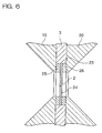
- Fig. 6 is an enlarged view of a portion C in Fig. 4.
- the particle detector 1 includes a plate member 3, a first cell 4, a second cell 5, and two through-shafts 8, 9.
- the plate member 3 has a through-hole 2 for particle detection.
- the first cell 4 includes a first cap member 15 and a cylindrical cell body 16, while the second cell 5 includes a second cap member 18 and a cylindrical second cell body 20.
- the plate member 3 may be constructed integrally with the first cell body 16 or the second cell body 20.
- the shafts 8, 9 extend through the first and second cell bodies 16, 20 provided on opposite sides of the plate member 3, and tubular stoppers 10, 11, 12, 13 are fitted around opposite end portions of the shafts 8, 9.
- Nuts 31 are threaded with male thread portions provided on opposite ends of the shafts 8, 9, so that the first and second cell bodies 16, 20 are liquid-tightly connected to the plate member 3 by clamping forces of the nuts 31.
- the first cap member 15 and the second cap member 18 include a nozzle 14 and a collection tube 17, respectively, which extend therethrough along center axes thereof.
- the first cap member 15 includes a projection 15a and a flange member 15b
- the second cap member 18 includes a projection 18a and a flange member 18b.
- the flange members 15b and 18b are respectively pressed against the first and second cell bodies 16 and 20 in engagement with annular portions 10a, 12a of the stoppers 10, 12 and the annular portions 11a, 13a of the stoppers 11, 13.
- first and second cap members 15 and 18 are liquid-tightly connected to the first and second cell bodies 16 and 20 via packings 21 and 22, respectively.
- the first and second cap members 15 and 18 are positioned by the shafts 8, 9 so that the nozzle 14, the through-hole 2 and the collection tube 17 are arranged coaxially with each other.
- the flange member 15b has insertion holes 32, 33, engagement holes 34, 35, and arcuate connection holes 36, 37 formed therein along arcs around an axis of the nozzle 14.
- the connection hole 36 connects the insertion hole 32 and the engagement hole 34
- the connection hole 37 connects the insertion hole 33 and the engagement hole 35.
- the insertion holes 32, 33 each have an inner diameter greater than the outer diameter of the annular portions 10a, 12a of the stoppers 10, 12.
- the engagement holes 34, 35 each have an inner diameter smaller than the outer diameter of the annular portions 10a, 12a.
- Band-shaped flanges 15c projecting from a surface of the flange member 15b are respectively provided along peripheral edges of the insertion hole 32, the connection hole 36 and the engagement hole 34 and along peripheral edges of the insertion hole 33, the connection hole 37 and the engagement hole 35. Portions of the flanges 15c surrounding the engagement holes 35 have a greater height than the other portions of the flanges 15c.
- the annular portions 10a, 12a overlie the portions of the flanges 15c surrounding the engagement holes 34, 35.
- the first cap member 15 is pressed against the first cell body 16 thereby to be liquid-tightly connected to the first cell body 16 via the packing 21.
- the flange member 18b has the same construction as the flange member 15b. Therefore, the second cap member 18 is liquid-tightly connected to the second cell body 20 via the packing 22 in the aforesaid manner.
- the plate member 3 includes a disk 24 provided in an opening 23 in a center portion thereof and having the through-hole 2, and two ring packings 25, 26 holding the disk 24 therebetween.
- the first and second cell bodies 16, 20 are liquid-tightly connected to the disk 24 via the packings 25, 26.
- the first cell body 16 includes a stainless steel nipple 6 inserted therein from an upper side, and a nipple 27 formed integrally therewith and extending downward.
- the nipple 6 receives and supplies a sheath liquid into the through-hole 2, so that a particle containing liquid injected from the nozzle 14 is enclosed in the sheath liquid to flow through the through-hole 2.
- a distal tip of the nipple 6 is exposed to the inside of the first cell body 16 so as to serve as an electrode (negative electrode) for measurement.
- the nipple 27 receives and sprays a cleaning liquid toward the through-hole 2 obliquely from a lower side. To this end, the nipple 27 has an angle of about 45 degrees with respect to the axis of the nozzle 14.
- the second cell body 20 includes nipples 28, 19 formed integrally therewith on its upper and lower sides, respectively.
- the nipple 19 receives and sprays the cleaning liquid toward the through-hole 2 obliquely from a lower side.
- the nipple 19 has an angle of about 45 degrees with respect to the axis of the collection tube 17.
- the nipple 28 is provided for discharging the cleaning liquid from the second cell body 20.
- the second cell body 20 includes a measurement electrode 7 (Fig. 4) exposed therein.
- the electrode 7 is a platinum electrode rod and serves as a positive electrode.
- the electrode 7 is fixed to the second cap member 18 parallel to the collection tube 17.
- the nozzle 14 includes a tube connector 29 provided at a tail end thereof.
- the collection tube 17 includes a tube connector 30 provided at a tail end thereof.
- the nozzle 14 is of stainless steel, and has an inner diameter of 0.2mm.
- the disk 24 is of artificial ruby, and has a thickness of 1mm.
- the diameter of the through-hole 2 varies depending on the size of a particle to be subjected to the measurement. In the case of red blood cells, the through-hole 2 has a diameter of 50 to 100 ⁇ m.
- the first and second cell bodies 16, 20, the first cap member 15 and the second cap member 18 are each produced by injection molding of a thermoplastic polyetherimide which is resistant to chemicals.
- the nipple 27 is formed integrally with the first cell body 16, and the nipples 19 and 28 are formed integrally with the second cell body 20.
- the nozzle 14, the electrode-doubled nipple 6 and the electrode 7 are press-fitted into the first cap member 15, the first cell body 16 and the second cap member 18, respectively, after the injection molding, and fixed by an adhesive.
- the second cap member 18 is withdrawn from the second cell body 20 by handling the flange member 18b in the same manner as described above. Then, the operator inserts a thin brush into the through-hole 2 from the openings of the first and second cell bodies 16, 20 to remove the substances deposited in and around the through-hole 2 from the opposite sides of the through-hole 2.
- the particle detector 1 is assembled to the original state in reserve order to the disassembling operation. More specifically, the operator holds the flange member 15b of the first cap member 15 to insert the annular members 10a, 12a of the stoppers 10, 12 into the insertion holes 32, 33 of the flange member 15b. At the same time, the projection 15a is inserted into the opening of the first cell body 16.
- the first cap member 15 is pressed against the first cell body 16, and liquid-tightly connected to the first cell body 16 via the packing 21.
- the second cap member 18 is liquid-tightly connected to the second cell body 20.
- Fig. 8 is a perspective view of the cover 59 for the particle detector 1.
- Fig. 9 is a perspective view illustrating a state where the cover 59 is opened
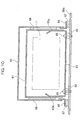
- Fig. 10 is a cross sectional view of the cover 59. As shown, the cover 59 is fixed by a screw 82. When the screw 82 is loosened and a knob 80 is pulled forward, the cover 59 is opened so that the particle detector 1 provided therein is exposed.
- the cover 59 is of a double structure including an outer cover 60 and an inner cover 61.
- the inner cover 61 includes a bottom plate 63, which is fixed on the front panel 58a via insulative bushes 62 by screws 65 of an insulative resin (see, Fig. 10).
- the bottom plate 63 includes two transverse auxiliary side plates 63a and two longitudinal auxiliary side plates 63b projecting from the periphery of the bottom plate 63.
- the auxiliary side plates 63a, 63b are brought into resilient contact with an interior surface of the inner cover 61 when the cover 59 is closed.
- a single auxiliary side plate 64 for the outer cover 60 is fixed to the front panel 58a by metal screws 81.
- the auxiliary side plate 64 is brought into resilient contact with an interior surface of the outer cover 60. Then, the outer cover 60 is fixed to the auxiliary side plate 64 by the metal screw 82.
- the outer cover 60 includes four contact plates 66 spot-welded to peripheral edges of an opening of the outer cover 60. Correspondingly to the contact plates 66, four electrically conductive elastic members 67 are fixed to the front panel 58a. When the cover 59 is closed, the four contact plates 66 are brought into resilient contact with the corresponding elastic members 67.
- the outer cover 60 is fixed to the inner cover 61 via insulative members 68.
- the inner cover 61 is supported by the two longitudinal auxiliary side plates 63b pivotally about two support pins 69, whereby the cover 59 can be opened and closed.
- the outer cover 60, the inner cover 61, the auxiliary side plates 63a, 63b, 64 and the contact plates 66 are formed from a metal plate (e.g., a stainless steel plate). Therefore, the particle detector 1 is enclosed by two conductive cases insulated from each other when the cover 59 is closed. It is noted that the electrically conductive elastic members 67 can easily be prepared by bonding electrically conductive tapes on sponge rubber pieces.
- Fig. 11 is a circuit diagram illustrating an electric circuit of the electrical resistance type detection section 53.
- the switching power supply circuit 71 transforms AC 100V into DC 5V and DC 12V, and outputs DC 5V and DC 12V with a ground line G employed as a common negative electrode.
- a booster circuit 72 boosts DC 12V to DC 56V, and inputs DC 56V to a constant electric current circuit 73 with its negative electrode connected to the ground line G.
- the constant electric current circuit 73 applies DC 56V under no load between the electrode 6 (negative electrode) and the electrode 7 (positive electrode) of the particle detector 1.
- an electrical resistance (or impedance) between the electrodes 6 and 7 changes, and the change is represented by a variation in voltage (voltage pulse) between the electrodes 6 and 7.
- the voltage between the electrodes 6 and 7 is amplified by an amplifier 74, and the amplified voltage is converted into a digital signal by an A/D converter 75.
- a computation circuit 76 calculates the size and number of particles and like data on the basis of the digital signal, and outputs the calculation results to the personal computer 102 (Fig. 1).
- the positive electrode and the negative electrode of the switching power supply circuit 71 are respectively connected to a power supply line H and the ground line G to output the 5V voltage.
- the amplifier 74, the A/D converter 75 and the computation circuit 76 are connected between the lines H and G, and driven by receiving the voltage from the lines H and G.
- the particle detector 1 is covered with the cover 59 of the double structure including the outer cover 60 and the inner cover 61.
- the outer cover 60 is grounded via the front panel 58a of the housing 58, and the inner cover 61 is connected to the ground line G of the electric circuit.
- the particle detector 1 is shielded from external noises, so that requirements of the EMC regulations related to the electromagnetic waves can be satisfied.
- the cleaning liquid is sprayed into and around the through-hole 2 from the nipples 19, 27 shown in Fig. 5 immediately before the measurement is performed on every sample, whereby air bubbles adhering or floating in and around the through-hole 2 are removed and discharged together with the cleaning liquid from the nipples 28, 6.
- the particle detector 1 ensures a higher level of detection accuracy.
- Fig. 12 is a flow circuit diagram of the electrical resistance type detection section 53 employing the particle detector 1. As shown, valves V1, V2 are opened, whereby a red blood cell measurement sample is sucked into a flow path P from a sample chamber SC by a negative pressure of a drainage chamber WC1 and retained in the flow path P. It is noted that the red blood cell measurement sample is prepared by diluting the blood sample in the dilution/reaction section 52 (Fig. 1) and preliminarily stored in the sample chamber SC.
- valves V1, V2 are closed and valves V3, V4, V5, V6 are opened, whereby a diluent is supplied as the cleaning liquid into the nipples 27, 19 from a diluent chamber DC by a positive pressure. Then, the diluent is sprayed in and around the through-hole 2 for cleaning the first and second cells 4, 5 and removing air bubbles, and discharged through the nipples 6, 28 into the drainage chamber WC1.
- valves V3, V4, V5, V6 are closed and a valve V7 is opened, whereby the diluent is supplied as the sheath liquid into the nipple 6 from the diluent chamber DC by a positive pressure and discharged into a drainage chamber WC2 through the through-hole 2 and the collection tube 17.
- a sheath liquid flow passing through the through-hole 2 is formed.
- a syringe pump CP is operated for discharge in this state, whereby the sample retained in the flow path P is pushed out to be injected into the through-hole 2 from the nozzle 14.
- the injected sample which is enclosed in the sheath liquid, passes through the through-hole 2, and is discharged into the drainage chamber WC2 through the collection tube 17.
- valves V2, V9 are opened (with the valve V8 kept open), whereby the diluent is supplied as the cleaning liquid into the syringe pump CP, a sample suction flow path and the sample chamber SC from the diluent chamber DC.
- valves V2, V8 are closed (with the valve V9 kept open) and the valve V1 is opened, whereby the diluent is supplied as the cleaning liquid into the syringe pump CP and the flow path P from the diluent chamber DC.
- valve V1 After a lapse of a predetermined period, the valve V1 is closed (with the valve V9 kept open), the diluent is supplied as the cleaning liquid into the syringe pump CP, the flow path P and the nozzle 14. After a lapse of a predetermined period, the valve V9 is closed to complete the cleaning.
Landscapes
- Chemical & Material Sciences (AREA)
- Dispersion Chemistry (AREA)
- Physics & Mathematics (AREA)
- Health & Medical Sciences (AREA)
- Life Sciences & Earth Sciences (AREA)
- Analytical Chemistry (AREA)
- Biochemistry (AREA)
- General Health & Medical Sciences (AREA)
- General Physics & Mathematics (AREA)
- Immunology (AREA)
- Pathology (AREA)
- Investigating Or Analysing Biological Materials (AREA)
- Steroid Compounds (AREA)
- Investigating Or Analyzing Materials By The Use Of Electric Means (AREA)
Applications Claiming Priority (8)
| Application Number | Priority Date | Filing Date | Title |
|---|---|---|---|
| JP2001366885 | 2001-11-30 | ||
| JP2001366885A JP3722743B2 (ja) | 2001-11-30 | 2001-11-30 | 粒子検出器およびそれを用いた粒子分析装置 |
| JP2001371513 | 2001-12-05 | ||
| JP2001371503A JP4212803B2 (ja) | 2001-12-05 | 2001-12-05 | 粒子測定装置 |
| JP2001371524 | 2001-12-05 | ||
| JP2001371503 | 2001-12-05 | ||
| JP2001371513A JP4112217B2 (ja) | 2001-12-05 | 2001-12-05 | 粒子検出器およびそれを用いた粒子分析装置 |
| JP2001371524A JP3737047B2 (ja) | 2001-12-05 | 2001-12-05 | 粒子検出器とそれを用いた粒子分析装置 |
Publications (3)
| Publication Number | Publication Date |
|---|---|
| EP1316792A2 true EP1316792A2 (de) | 2003-06-04 |
| EP1316792A3 EP1316792A3 (de) | 2004-02-04 |
| EP1316792B1 EP1316792B1 (de) | 2009-09-16 |
Family
ID=27482713
Family Applications (1)
| Application Number | Title | Priority Date | Filing Date |
|---|---|---|---|
| EP02026319A Expired - Lifetime EP1316792B1 (de) | 2001-11-30 | 2002-11-21 | Teilchenanalysator |
Country Status (4)
| Country | Link |
|---|---|
| US (1) | US6909269B2 (de) |
| EP (1) | EP1316792B1 (de) |
| AT (1) | ATE443252T1 (de) |
| DE (1) | DE60233708D1 (de) |
Cited By (7)
| Publication number | Priority date | Publication date | Assignee | Title |
|---|---|---|---|---|
| CN101236149B (zh) * | 2007-02-02 | 2011-04-20 | 深圳迈瑞生物医疗电子股份有限公司 | 一种流式细胞检测装置及其实现的流式细胞检测方法 |
| CN101246180B (zh) * | 2007-02-16 | 2012-11-21 | 深圳迈瑞生物医疗电子股份有限公司 | 一种血液细胞分析仪清洁液自动灌注方法及装置 |
| CN103091232A (zh) * | 2011-10-31 | 2013-05-08 | 深圳迈瑞生物医疗电子股份有限公司 | 粒子分析仪及其粒子测试控制方法、装置 |
| CN101451990B (zh) * | 2007-11-29 | 2013-08-28 | 深圳迈瑞生物医疗电子股份有限公司 | 一种体积计量装置及其清洗方法 |
| EP2567756A3 (de) * | 2011-09-07 | 2014-08-20 | Gottfried Wilhelm Leibniz Universität Hannover | Vorrichtung zum Aufbringen eines Mediums auf ein Objekt und Verfahren zur Detektion von Abweichungen eines Sprühfeldes |
| CN104296953B (zh) * | 2013-07-16 | 2017-03-15 | 成都深迈瑞医疗电子技术研究院有限公司 | 一种微孔堵孔检测方法和系统、血液细胞分析仪 |
| CN113640196A (zh) * | 2021-02-03 | 2021-11-12 | 深圳市帝迈生物技术有限公司 | 试剂盒、poct血细胞分析仪 |
Families Citing this family (22)
| Publication number | Priority date | Publication date | Assignee | Title |
|---|---|---|---|---|
| CN101165485B (zh) * | 2006-10-18 | 2012-09-19 | 深圳迈瑞生物医疗电子股份有限公司 | 一种血液细胞检测的装置及其微孔传感器组件 |
| CN101173887B (zh) * | 2006-11-02 | 2011-04-06 | 深圳迈瑞生物医疗电子股份有限公司 | 鞘流阻抗法粒子分析仪 |
| US7656146B2 (en) * | 2006-11-02 | 2010-02-02 | Shenzhen Mindray Bio-Medical Electronics Co., Ltd. | Particle analyzer based on sheath flow impedance method |
| JP5203889B2 (ja) * | 2008-10-28 | 2013-06-05 | シスメックス株式会社 | 検体分析装置及び検体分析方法 |
| US8717045B2 (en) * | 2010-10-20 | 2014-05-06 | Panasonic Healthcare Co., Ltd. | Microorganism number measurement device |
| JP5456653B2 (ja) * | 2010-12-13 | 2014-04-02 | 日本光電工業株式会社 | 血液測定装置 |
| CN105092454B (zh) | 2010-12-28 | 2018-05-01 | 深圳迈瑞生物医疗电子股份有限公司 | 计数器及流式细胞分析仪 |
| CN102564918B (zh) * | 2010-12-31 | 2015-12-02 | 深圳迈瑞生物医疗电子股份有限公司 | 粒子计数装置和血液细胞分析装置 |
| US9329106B2 (en) * | 2014-02-28 | 2016-05-03 | Uop Llc | Methods, apparatuses and kits for collecting chemical samples |
| CN105784571B (zh) * | 2016-02-29 | 2023-05-26 | 深圳市帝迈生物技术有限公司 | 一种特定反应蛋白crp的双池子测量方法及装置 |
| WO2019127563A1 (zh) * | 2017-12-30 | 2019-07-04 | 深圳迈瑞生物医疗电子股份有限公司 | 鞘流阻抗法粒子分析仪及其测量方法 |
| WO2019206311A1 (zh) * | 2018-04-28 | 2019-10-31 | 深圳迈瑞生物医疗电子股份有限公司 | 血液分析系统、血液分析仪、血液分析方法及存储介质 |
| US10876949B2 (en) | 2019-04-26 | 2020-12-29 | Honeywell International Inc. | Flow device and associated method and system |
| US11047787B2 (en) | 2019-04-29 | 2021-06-29 | Research Triangle Institute | And method for optical bench for detecting particles |
| US20230010400A1 (en) * | 2019-12-04 | 2023-01-12 | Ian Basil Shine | Improved methods and devices for measuring cell numbers and/or cell properties |
| US11391613B2 (en) * | 2020-02-14 | 2022-07-19 | Honeywell International Inc. | Fluid composition sensor device and method of using the same |
| US11333593B2 (en) | 2020-02-14 | 2022-05-17 | Honeywell International Inc. | Fluid composition sensor device and method of using the same |
| US12111257B2 (en) | 2020-08-26 | 2024-10-08 | Honeywell International Inc. | Fluid composition sensor device and method of using the same |
| US11835432B2 (en) | 2020-10-26 | 2023-12-05 | Honeywell International Inc. | Fluid composition sensor device and method of using the same |
| US11733144B2 (en) | 2020-12-14 | 2023-08-22 | Caterpillar Inc. | Convertible housing assembly for a particle sensor |
| WO2022165682A1 (zh) * | 2021-02-03 | 2022-08-11 | 深圳市帝迈生物技术有限公司 | 试剂盒、样本检测装置 |
| CN115248319A (zh) * | 2021-04-26 | 2022-10-28 | 深圳市帝迈生物技术有限公司 | Poct血细胞分析仪及其使用方法 |
Family Cites Families (18)
| Publication number | Priority date | Publication date | Assignee | Title |
|---|---|---|---|---|
| US3340471A (en) * | 1966-08-22 | 1967-09-05 | Coulter Electronics | Flow-through sample apparatus for use with electrical particle study device |
| US3515884A (en) * | 1967-05-17 | 1970-06-02 | Toa Electric Co Ltd | Detecting and counting apparatus for particles suspended in a liquid |
| GB1348881A (en) * | 1970-02-27 | 1974-03-27 | Smiths Industries Ltd | Particle detection apparatus |
| US3688191A (en) * | 1970-09-10 | 1972-08-29 | Coulter Electronics | Electronic particle study apparatus with fluid circulating system |
| BE793185A (fr) * | 1971-12-23 | 1973-04-16 | Atomic Energy Commission | Appareil pour analyser et trier rapidement des particules telles que des cellules biologiques |
| US3783376A (en) * | 1972-06-21 | 1974-01-01 | Becton Dickinson Co | Particle counter having removable aperture slide |
| US4070617A (en) * | 1974-05-08 | 1978-01-24 | Max-Planck-Gesellschaft Zur Forderung Der Wissenschaften E.V. | Device for controlling the particle flow in an apparatus for measuring the properties of particles suspended in liquid |
| US3958177A (en) * | 1974-12-17 | 1976-05-18 | Sherwood Medical Industries Inc. | Particle analyzing device with changeable aperture means |
| US4375615A (en) * | 1979-04-20 | 1983-03-01 | Becton Dickinson And Company | Apparatus for counting particles in a liquid suspension |
| JPS58129349A (ja) * | 1982-01-29 | 1983-08-02 | Olympus Optical Co Ltd | 微小粒子計数装置の目詰り除去装置 |
| US4564803A (en) * | 1983-08-29 | 1986-01-14 | Coulter Corporation | Method and apparatus for removing foreign matter from a flow cell of a particle study device |
| JPS61160038A (ja) * | 1985-01-08 | 1986-07-19 | Sumitomo Electric Ind Ltd | 粒子検出器 |
| CA1328679C (en) * | 1989-05-18 | 1994-04-19 | Raynald Hachey | Apparatus for particle determination in liquid metals |
| JP3499003B2 (ja) * | 1994-07-05 | 2004-02-23 | シスメックス株式会社 | 粒度分布測定装置 |
| JPH09318522A (ja) * | 1996-05-29 | 1997-12-12 | Toa Medical Electronics Co Ltd | 粒子検出器及び粒子分析装置 |
| GB9624096D0 (en) * | 1996-11-20 | 1997-01-08 | Microbial Systems Ltd | Apparatus and method of use thereof |
| JP3282071B2 (ja) | 1997-09-05 | 2002-05-13 | 株式会社ヒューマン | ノイズ遮蔽ラック |
| JP3888804B2 (ja) | 1999-07-16 | 2007-03-07 | シスメックス株式会社 | 粒子測定装置 |
-
2002
- 2002-11-21 AT AT02026319T patent/ATE443252T1/de not_active IP Right Cessation
- 2002-11-21 EP EP02026319A patent/EP1316792B1/de not_active Expired - Lifetime
- 2002-11-21 DE DE60233708T patent/DE60233708D1/de not_active Expired - Lifetime
- 2002-11-27 US US10/305,146 patent/US6909269B2/en not_active Expired - Lifetime
Cited By (10)
| Publication number | Priority date | Publication date | Assignee | Title |
|---|---|---|---|---|
| CN101236149B (zh) * | 2007-02-02 | 2011-04-20 | 深圳迈瑞生物医疗电子股份有限公司 | 一种流式细胞检测装置及其实现的流式细胞检测方法 |
| CN101246180B (zh) * | 2007-02-16 | 2012-11-21 | 深圳迈瑞生物医疗电子股份有限公司 | 一种血液细胞分析仪清洁液自动灌注方法及装置 |
| CN101451990B (zh) * | 2007-11-29 | 2013-08-28 | 深圳迈瑞生物医疗电子股份有限公司 | 一种体积计量装置及其清洗方法 |
| EP2567756A3 (de) * | 2011-09-07 | 2014-08-20 | Gottfried Wilhelm Leibniz Universität Hannover | Vorrichtung zum Aufbringen eines Mediums auf ein Objekt und Verfahren zur Detektion von Abweichungen eines Sprühfeldes |
| CN103091232A (zh) * | 2011-10-31 | 2013-05-08 | 深圳迈瑞生物医疗电子股份有限公司 | 粒子分析仪及其粒子测试控制方法、装置 |
| CN104296953B (zh) * | 2013-07-16 | 2017-03-15 | 成都深迈瑞医疗电子技术研究院有限公司 | 一种微孔堵孔检测方法和系统、血液细胞分析仪 |
| CN113640196A (zh) * | 2021-02-03 | 2021-11-12 | 深圳市帝迈生物技术有限公司 | 试剂盒、poct血细胞分析仪 |
| CN113686759A (zh) * | 2021-02-03 | 2021-11-23 | 深圳市帝迈生物技术有限公司 | 试剂盒、poct血细胞分析仪 |
| CN113686759B (zh) * | 2021-02-03 | 2023-11-24 | 深圳市帝迈生物技术有限公司 | 试剂盒、poct血细胞分析仪 |
| CN113640196B (zh) * | 2021-02-03 | 2023-12-01 | 深圳市帝迈生物技术有限公司 | 试剂盒、poct血细胞分析仪 |
Also Published As
| Publication number | Publication date |
|---|---|
| US6909269B2 (en) | 2005-06-21 |
| US20030102220A1 (en) | 2003-06-05 |
| DE60233708D1 (de) | 2009-10-29 |
| ATE443252T1 (de) | 2009-10-15 |
| EP1316792B1 (de) | 2009-09-16 |
| EP1316792A3 (de) | 2004-02-04 |
Similar Documents
| Publication | Publication Date | Title |
|---|---|---|
| EP1316792B1 (de) | Teilchenanalysator | |
| US8828212B2 (en) | Dielectric cytometric apparatus and dielectric-cytometric cell sorting method | |
| US4165484A (en) | Particle counting apparatus utilizing various fluid resistors to maintain proper pressure differentials | |
| EP0582320A2 (de) | Messgerät und Verfahren | |
| US6417658B1 (en) | Flow cell for particle analyzer using electrical sensing zone method | |
| US5296123A (en) | In-tank electrochemical sensor | |
| EP0478392A2 (de) | Teilchenanalysator und Druchflusszelle dafür | |
| US8256273B2 (en) | Device and method for measuring fine particle concentration | |
| US4130754A (en) | Particle counting | |
| EP1929273B1 (de) | Nachweis und anschliessende entfernung einer öffnungsblockade | |
| US20010032495A1 (en) | Particle signal processing apparatus and particle measurement apparatus using same | |
| US6418802B1 (en) | Particle sizing apparatus and method of use thereof | |
| JP3737047B2 (ja) | 粒子検出器とそれを用いた粒子分析装置 | |
| JP4241740B2 (ja) | 試料測定方法 | |
| JP4212803B2 (ja) | 粒子測定装置 | |
| JP4112217B2 (ja) | 粒子検出器およびそれを用いた粒子分析装置 | |
| CN205826667U (zh) | 一次性血液细胞计数及分析集成件以及新型血液分析仪 | |
| JP2006171010A5 (de) | ||
| CN205826668U (zh) | 一次性血液细胞计数及分析集成试剂传感件及血液分析仪 | |
| KR100518504B1 (ko) | 혈구 카운터 | |
| JP2005091098A (ja) | 血球計数装置 | |
| JP3722743B2 (ja) | 粒子検出器およびそれを用いた粒子分析装置 | |
| CN108535462A (zh) | 一种具有自主清洗消毒能力的血液分析仪 | |
| JPH11500217A (ja) | 体積確認装置および方法 | |
| US11567027B2 (en) | Analysis of a test sample |
Legal Events
| Date | Code | Title | Description |
|---|---|---|---|
| PUAI | Public reference made under article 153(3) epc to a published international application that has entered the european phase |
Free format text: ORIGINAL CODE: 0009012 |
|
| AK | Designated contracting states |
Designated state(s): AT BE BG CH CY CZ DE DK EE ES FI FR GB GR IE IT LI LU MC NL PT SE SK TR |
|
| AX | Request for extension of the european patent |
Extension state: AL LT LV MK RO SI |
|
| PUAL | Search report despatched |
Free format text: ORIGINAL CODE: 0009013 |
|
| RIC1 | Information provided on ipc code assigned before grant |
Ipc: 7G 01N 15/14 B Ipc: 7G 01N 15/12 A |
|
| AK | Designated contracting states |
Kind code of ref document: A3 Designated state(s): AT BE BG CH CY CZ DE DK EE ES FI FR GB GR IE IT LI LU MC NL PT SE SK TR |
|
| AX | Request for extension of the european patent |
Extension state: AL LT LV MK RO SI |
|
| 17P | Request for examination filed |
Effective date: 20040315 |
|
| AKX | Designation fees paid |
Designated state(s): AT BE BG CH CY CZ DE DK EE ES FI FR GB GR IE IT LI LU MC NL PT SE SK TR |
|
| 17Q | First examination report despatched |
Effective date: 20061109 |
|
| GRAP | Despatch of communication of intention to grant a patent |
Free format text: ORIGINAL CODE: EPIDOSNIGR1 |
|
| RTI1 | Title (correction) |
Free format text: PARTICLE ANALYZER |
|
| GRAS | Grant fee paid |
Free format text: ORIGINAL CODE: EPIDOSNIGR3 |
|
| GRAA | (expected) grant |
Free format text: ORIGINAL CODE: 0009210 |
|
| AK | Designated contracting states |
Kind code of ref document: B1 Designated state(s): AT BE BG CH CY CZ DE DK EE ES FI FR GB GR IE IT LI LU MC NL PT SE SK TR |
|
| REG | Reference to a national code |
Ref country code: GB Ref legal event code: FG4D |
|
| REG | Reference to a national code |
Ref country code: CH Ref legal event code: EP |
|
| REG | Reference to a national code |
Ref country code: IE Ref legal event code: FG4D |
|
| REF | Corresponds to: |
Ref document number: 60233708 Country of ref document: DE Date of ref document: 20091029 Kind code of ref document: P |
|
| PG25 | Lapsed in a contracting state [announced via postgrant information from national office to epo] |
Ref country code: SE Free format text: LAPSE BECAUSE OF FAILURE TO SUBMIT A TRANSLATION OF THE DESCRIPTION OR TO PAY THE FEE WITHIN THE PRESCRIBED TIME-LIMIT Effective date: 20090916 Ref country code: FI Free format text: LAPSE BECAUSE OF FAILURE TO SUBMIT A TRANSLATION OF THE DESCRIPTION OR TO PAY THE FEE WITHIN THE PRESCRIBED TIME-LIMIT Effective date: 20090916 |
|
| PG25 | Lapsed in a contracting state [announced via postgrant information from national office to epo] |
Ref country code: NL Free format text: LAPSE BECAUSE OF FAILURE TO SUBMIT A TRANSLATION OF THE DESCRIPTION OR TO PAY THE FEE WITHIN THE PRESCRIBED TIME-LIMIT Effective date: 20090916 |
|
| NLV1 | Nl: lapsed or annulled due to failure to fulfill the requirements of art. 29p and 29m of the patents act | ||
| PG25 | Lapsed in a contracting state [announced via postgrant information from national office to epo] |
Ref country code: CY Free format text: LAPSE BECAUSE OF FAILURE TO SUBMIT A TRANSLATION OF THE DESCRIPTION OR TO PAY THE FEE WITHIN THE PRESCRIBED TIME-LIMIT Effective date: 20090916 |
|
| PG25 | Lapsed in a contracting state [announced via postgrant information from national office to epo] |
Ref country code: ES Free format text: LAPSE BECAUSE OF FAILURE TO SUBMIT A TRANSLATION OF THE DESCRIPTION OR TO PAY THE FEE WITHIN THE PRESCRIBED TIME-LIMIT Effective date: 20091227 Ref country code: PT Free format text: LAPSE BECAUSE OF FAILURE TO SUBMIT A TRANSLATION OF THE DESCRIPTION OR TO PAY THE FEE WITHIN THE PRESCRIBED TIME-LIMIT Effective date: 20100118 Ref country code: CZ Free format text: LAPSE BECAUSE OF FAILURE TO SUBMIT A TRANSLATION OF THE DESCRIPTION OR TO PAY THE FEE WITHIN THE PRESCRIBED TIME-LIMIT Effective date: 20090916 Ref country code: EE Free format text: LAPSE BECAUSE OF FAILURE TO SUBMIT A TRANSLATION OF THE DESCRIPTION OR TO PAY THE FEE WITHIN THE PRESCRIBED TIME-LIMIT Effective date: 20090916 |
|
| PG25 | Lapsed in a contracting state [announced via postgrant information from national office to epo] |
Ref country code: SK Free format text: LAPSE BECAUSE OF FAILURE TO SUBMIT A TRANSLATION OF THE DESCRIPTION OR TO PAY THE FEE WITHIN THE PRESCRIBED TIME-LIMIT Effective date: 20090916 |
|
| PG25 | Lapsed in a contracting state [announced via postgrant information from national office to epo] |
Ref country code: MC Free format text: LAPSE BECAUSE OF NON-PAYMENT OF DUE FEES Effective date: 20091130 Ref country code: BE Free format text: LAPSE BECAUSE OF FAILURE TO SUBMIT A TRANSLATION OF THE DESCRIPTION OR TO PAY THE FEE WITHIN THE PRESCRIBED TIME-LIMIT Effective date: 20090916 Ref country code: AT Free format text: LAPSE BECAUSE OF FAILURE TO SUBMIT A TRANSLATION OF THE DESCRIPTION OR TO PAY THE FEE WITHIN THE PRESCRIBED TIME-LIMIT Effective date: 20090916 |
|
| REG | Reference to a national code |
Ref country code: CH Ref legal event code: PL |
|
| PLBE | No opposition filed within time limit |
Free format text: ORIGINAL CODE: 0009261 |
|
| STAA | Information on the status of an ep patent application or granted ep patent |
Free format text: STATUS: NO OPPOSITION FILED WITHIN TIME LIMIT |
|
| PG25 | Lapsed in a contracting state [announced via postgrant information from national office to epo] |
Ref country code: DK Free format text: LAPSE BECAUSE OF FAILURE TO SUBMIT A TRANSLATION OF THE DESCRIPTION OR TO PAY THE FEE WITHIN THE PRESCRIBED TIME-LIMIT Effective date: 20090916 |
|
| 26N | No opposition filed |
Effective date: 20100617 |
|
| PG25 | Lapsed in a contracting state [announced via postgrant information from national office to epo] |
Ref country code: LI Free format text: LAPSE BECAUSE OF NON-PAYMENT OF DUE FEES Effective date: 20091130 Ref country code: IE Free format text: LAPSE BECAUSE OF NON-PAYMENT OF DUE FEES Effective date: 20091121 Ref country code: GR Free format text: LAPSE BECAUSE OF FAILURE TO SUBMIT A TRANSLATION OF THE DESCRIPTION OR TO PAY THE FEE WITHIN THE PRESCRIBED TIME-LIMIT Effective date: 20091217 Ref country code: CH Free format text: LAPSE BECAUSE OF NON-PAYMENT OF DUE FEES Effective date: 20091130 |
|
| PG25 | Lapsed in a contracting state [announced via postgrant information from national office to epo] |
Ref country code: IT Free format text: LAPSE BECAUSE OF FAILURE TO SUBMIT A TRANSLATION OF THE DESCRIPTION OR TO PAY THE FEE WITHIN THE PRESCRIBED TIME-LIMIT Effective date: 20090916 Ref country code: BG Free format text: LAPSE BECAUSE OF FAILURE TO SUBMIT A TRANSLATION OF THE DESCRIPTION OR TO PAY THE FEE WITHIN THE PRESCRIBED TIME-LIMIT Effective date: 20091130 |
|
| PG25 | Lapsed in a contracting state [announced via postgrant information from national office to epo] |
Ref country code: LU Free format text: LAPSE BECAUSE OF NON-PAYMENT OF DUE FEES Effective date: 20091121 |
|
| PG25 | Lapsed in a contracting state [announced via postgrant information from national office to epo] |
Ref country code: TR Free format text: LAPSE BECAUSE OF FAILURE TO SUBMIT A TRANSLATION OF THE DESCRIPTION OR TO PAY THE FEE WITHIN THE PRESCRIBED TIME-LIMIT Effective date: 20090916 |
|
| REG | Reference to a national code |
Ref country code: FR Ref legal event code: PLFP Year of fee payment: 14 |
|
| REG | Reference to a national code |
Ref country code: FR Ref legal event code: PLFP Year of fee payment: 15 |
|
| REG | Reference to a national code |
Ref country code: FR Ref legal event code: PLFP Year of fee payment: 16 |
|
| REG | Reference to a national code |
Ref country code: FR Ref legal event code: PLFP Year of fee payment: 17 |
|
| PGFP | Annual fee paid to national office [announced via postgrant information from national office to epo] |
Ref country code: GB Payment date: 20210930 Year of fee payment: 20 |
|
| PGFP | Annual fee paid to national office [announced via postgrant information from national office to epo] |
Ref country code: DE Payment date: 20210929 Year of fee payment: 20 Ref country code: FR Payment date: 20211109 Year of fee payment: 20 |
|
| REG | Reference to a national code |
Ref country code: DE Ref legal event code: R071 Ref document number: 60233708 Country of ref document: DE |
|
| REG | Reference to a national code |
Ref country code: GB Ref legal event code: PE20 Expiry date: 20221120 |
|
| PG25 | Lapsed in a contracting state [announced via postgrant information from national office to epo] |
Ref country code: GB Free format text: LAPSE BECAUSE OF EXPIRATION OF PROTECTION Effective date: 20221120 |