EP1317018A2 - Raumfüllendes Anti-Radar und/oder Mehrebenen-Radarstörverteiler - Google Patents
Raumfüllendes Anti-Radar und/oder Mehrebenen-Radarstörverteiler Download PDFInfo
- Publication number
- EP1317018A2 EP1317018A2 EP02380242A EP02380242A EP1317018A2 EP 1317018 A2 EP1317018 A2 EP 1317018A2 EP 02380242 A EP02380242 A EP 02380242A EP 02380242 A EP02380242 A EP 02380242A EP 1317018 A2 EP1317018 A2 EP 1317018A2
- Authority
- EP
- European Patent Office
- Prior art keywords
- disperser
- chaff
- radar
- space
- dispersers
- Prior art date
- Legal status (The legal status is an assumption and is not a legal conclusion. Google has not performed a legal analysis and makes no representation as to the accuracy of the status listed.)
- Withdrawn
Links
- 239000000725 suspension Substances 0.000 claims abstract description 11
- 239000000463 material Substances 0.000 claims description 10
- 239000000758 substrate Substances 0.000 claims description 6
- 239000003989 dielectric material Substances 0.000 claims description 5
- 239000000203 mixture Substances 0.000 claims description 5
- 239000004020 conductor Substances 0.000 claims description 4
- 239000011152 fibreglass Substances 0.000 claims description 3
- 229920002972 Acrylic fiber Polymers 0.000 claims description 2
- 229920002799 BoPET Polymers 0.000 claims description 2
- 229920004934 Dacron® Polymers 0.000 claims description 2
- 239000005041 Mylar™ Substances 0.000 claims description 2
- 239000004677 Nylon Substances 0.000 claims description 2
- 239000004952 Polyamide Substances 0.000 claims description 2
- 229920000297 Rayon Polymers 0.000 claims description 2
- 239000004809 Teflon Substances 0.000 claims description 2
- 229920006362 Teflon® Polymers 0.000 claims description 2
- 230000008878 coupling Effects 0.000 claims description 2
- 238000010168 coupling process Methods 0.000 claims description 2
- 238000005859 coupling reaction Methods 0.000 claims description 2
- 229920001778 nylon Polymers 0.000 claims description 2
- 239000000123 paper Substances 0.000 claims description 2
- 229920003223 poly(pyromellitimide-1,4-diphenyl ether) Polymers 0.000 claims description 2
- 229920002647 polyamide Polymers 0.000 claims description 2
- 229920000728 polyester Polymers 0.000 claims description 2
- 239000005020 polyethylene terephthalate Substances 0.000 claims description 2
- 239000002964 rayon Substances 0.000 claims description 2
- 230000002459 sustained effect Effects 0.000 claims 1
- 230000004044 response Effects 0.000 description 17
- 238000000034 method Methods 0.000 description 15
- 230000006835 compression Effects 0.000 description 10
- 238000007906 compression Methods 0.000 description 10
- 230000000694 effects Effects 0.000 description 7
- 230000008901 benefit Effects 0.000 description 6
- 238000004519 manufacturing process Methods 0.000 description 6
- 238000005538 encapsulation Methods 0.000 description 5
- 238000004806 packaging method and process Methods 0.000 description 5
- 230000009467 reduction Effects 0.000 description 5
- 239000011888 foil Substances 0.000 description 4
- 235000015842 Hesperis Nutrition 0.000 description 2
- 235000012633 Iberis amara Nutrition 0.000 description 2
- 230000000295 complement effect Effects 0.000 description 2
- 239000006185 dispersion Substances 0.000 description 2
- 230000005484 gravity Effects 0.000 description 2
- 230000006872 improvement Effects 0.000 description 2
- 230000001788 irregular Effects 0.000 description 2
- 238000005304 joining Methods 0.000 description 2
- 239000002184 metal Substances 0.000 description 2
- 229910052751 metal Inorganic materials 0.000 description 2
- 239000004033 plastic Substances 0.000 description 2
- 229920003023 plastic Polymers 0.000 description 2
- 230000010287 polarization Effects 0.000 description 2
- 150000003839 salts Chemical class 0.000 description 2
- 230000003595 spectral effect Effects 0.000 description 2
- 229910001369 Brass Inorganic materials 0.000 description 1
- RYGMFSIKBFXOCR-UHFFFAOYSA-N Copper Chemical compound [Cu] RYGMFSIKBFXOCR-UHFFFAOYSA-N 0.000 description 1
- 229920000742 Cotton Polymers 0.000 description 1
- 239000004698 Polyethylene Substances 0.000 description 1
- 239000004115 Sodium Silicate Substances 0.000 description 1
- FRVYHNOKNOMTQH-UHFFFAOYSA-N [N]N(F)F Chemical compound [N]N(F)F FRVYHNOKNOMTQH-UHFFFAOYSA-N 0.000 description 1
- 239000005030 aluminium foil Substances 0.000 description 1
- 230000003466 anti-cipated effect Effects 0.000 description 1
- 230000005540 biological transmission Effects 0.000 description 1
- 238000009954 braiding Methods 0.000 description 1
- 239000010951 brass Substances 0.000 description 1
- 238000005253 cladding Methods 0.000 description 1
- 239000010949 copper Substances 0.000 description 1
- 229910052802 copper Inorganic materials 0.000 description 1
- 238000000354 decomposition reaction Methods 0.000 description 1
- 238000009826 distribution Methods 0.000 description 1
- 239000004744 fabric Substances 0.000 description 1
- 210000003746 feather Anatomy 0.000 description 1
- 239000006193 liquid solution Substances 0.000 description 1
- 230000007774 longterm Effects 0.000 description 1
- 239000011859 microparticle Substances 0.000 description 1
- 239000002245 particle Substances 0.000 description 1
- -1 polyethylene Polymers 0.000 description 1
- 229920000573 polyethylene Polymers 0.000 description 1
- 230000008569 process Effects 0.000 description 1
- 230000002035 prolonged effect Effects 0.000 description 1
- 230000005855 radiation Effects 0.000 description 1
- 239000004065 semiconductor Substances 0.000 description 1
- 238000005549 size reduction Methods 0.000 description 1
- NTHWMYGWWRZVTN-UHFFFAOYSA-N sodium silicate Chemical compound [Na+].[Na+].[O-][Si]([O-])=O NTHWMYGWWRZVTN-UHFFFAOYSA-N 0.000 description 1
- 229910052911 sodium silicate Inorganic materials 0.000 description 1
- 239000007787 solid Substances 0.000 description 1
- 239000007921 spray Substances 0.000 description 1
- 239000000126 substance Substances 0.000 description 1
- 210000002268 wool Anatomy 0.000 description 1
Images











Classifications
-
- H—ELECTRICITY
- H01—ELECTRIC ELEMENTS
- H01Q—ANTENNAS, i.e. RADIO AERIALS
- H01Q15/00—Devices for reflection, refraction, diffraction or polarisation of waves radiated from an antenna, e.g. quasi-optical devices
- H01Q15/14—Reflecting surfaces; Equivalent structures
- H01Q15/145—Reflecting surfaces; Equivalent structures comprising a plurality of reflecting particles, e.g. radar chaff
Definitions
- Chaff was one in the first forms of countermeasure employed against radar. It usually consists of a large number of electromagnetic dispersers and reflectors, normally arranged in form of strips of metal foil packed in a bundle. When they are released by an aircraft or distributed by rockets launched by a ship, most of the strips of foil which constitute the chaff bale are dispersed by the effect of the wind and become highly reflective clouds.
- Chaff is a relatively slow target. Its vertical descent is determined by the force of gravity and for the properties to resist advance presented by the strips of individual leaves. Chaff was a very effective countermeasure when using slow bomber aircraft during the Second World War. Chaff is usually employed to foil or to confuse surveillance and tracking radar. Miscellaneous reference information on radar chaff can be found in M.I. Skolnik's "Introduction to Radar Systems", McGraw-Hill, London, 1981.
- the heart of the present invention lies in the geometry of the dispersers or reflectors which improve the properties of radar chaff.
- Multilevel and space-filling antennas are distinguished in being of reduced size and having a multiband behaviour, as has been expounded already in patent publications WO0154225 and WO0122528 respectively.
- dispersers used in the present invention are not antennas, and that the features required of antennas are different with regard to those required by radar chaff.
- Antennas are used to transmit and receive associated signals to or from a transceiver by means of a transmission line or a radiofrequency network.
- the main electrical characteristic of a radar chaff disperser is its radar cross-section (RCS) which is related with the reflective capability of the disperser, and which cannot be anticipated by the characteristic parameters of the antennas.
- the chaff dispersers expounded in the present invention are mainly electromagnetic reflectors constituted of a conducting, semiconducting or superconducting material with a new geometry which improves the properties of the chaff.
- the new geometry facilitates a large RCS compared with dispersers presented in previous inventions having the same size; surprisingly the RCS is equivalent to that of conventional dispersers of greater size.
- the essence of the invention consists of the particular geometry of the reflectors or dispersers which constitute the cloud of radar chaff. Instead of using conventional rectilinear forms, in the present invention multilevel and space-filling forms are introduced. Due to this geometric design, the properties of the clouds of radar chaff are improved mainly in two aspects: radar cross-section (RCS) and mean time of suspension.
- RCS radar cross-section
- a space-filling curve for a chaff disperser is defined as: a curve comprising at least ten segments which are connected so that each element forms an angle with its neighbours, no pair of these segments defines a longer straight segment, these segments being smaller than a tenth part of the resonant wavelength in free space of the entire structure of the disperser.
- the size of the entire disperser is smaller than a quarter of the lowest operating wavelength.
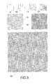
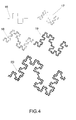
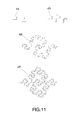
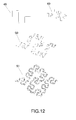
- Figures 1 to 12 show several examples of space-filling curves which can be used according to the present invention.
- the space-filling curves are long in terms of physical length but small in terms of area in which the curve can be included.
- the dispersers with space-filling form are long electrically but can be included in a very small surface area. This means it is possible to obtain a smaller packaging and a denser chaff cloud using this technique.
- Another characteristic of the space-filling dispersers is their frequency response.
- Their complex geometry provides a spectrally richer signature when compared with rectilinear dispersers known in the state of the art.
- Non-harmonic frequency responses are obtained with pass-bands and stop-bands distributed unequally, which is of great utility when the intention is to improve the clutter effect of the chaff cloud over a wider margin of radar frequencies.
- SFC space-filling curves
- a curve is a one-dimensional object; nevertheless, when the curve is highly complex and its physical length is very large, the curve tends to fill part of the surface which comprises it; in this case the Hausdorff dimension can be calculated on the curve (or at least an approximation to this by means of the mathematical algorithm known as box-counting) giving a number larger than unity as a result.
- box-counting the mathematical algorithm known as box-counting
- the space-filling properties of SFC dispersers hot only introduce an advantage in terms of reflected radar signal response, but also in terms of the aerodynamic profile of said dispersers. It is known that a surface offers greater resistance to air than a line or a one-dimensional form. Therefore, giving form to the dispersers with SFC with a dimension greater than unity (D> 1), increases resistance to the air and improves the time of suspension. In the case of SFC with D approaching 2 (like for example the designs in Fig. 1 and Fig.3), the surface-like behaviour is maximized, and for this reason a disperser is obtained which has a reflection response similar to a linear form, but which is smaller and at the same time is characterised in that it has a resistance to air proper to that of a surface. Although the improvement in time of suspension and resistance to advance are directly related with the geometry presented in the present invention, this effect is totally different to the electromagnetic one and it cannot be deduced or predicted from the electromagnetic properties of the dispersers.
- Multilevel structures are a geometry related with space-filling curves.
- a multilevel structure for radar chaff is defined as: a structure which includes a set of polygons, which are characterised in having the same number of sides, wherein these polygons are electromagnetically coupled either by means of capacitive coupling, or by means of an ohmic contact, where the region of contact between the directly connected polygons is smaller than 50% of the perimeter of the polygons mentioned in at least 75% of the polygons that constitute the defined multilevel structure.
- the global geometry of the whole structure is different to the geometry of the polygons which form it.
- multilevel structures provide both a reduction in the sizes of dispersers and an enhancement of their frequency response.
- the dispersers which are at least partially formed by multilevel structures will be smaller than those described in the state of the art, and they provided a better multiband response.
- Multilevel structures can resonate in a non-harmonic way, and can even cover simultaneously and with the same relative bandwidth at least a portion of numerous bands: HF, VHF, UHF, L, S, C, X, Ku, K, Ka and mm.
- multilevel structures for radar chaff also provide a better aerodynamic profile with respect to chaff of the state of the art.
- Multilevel structures are characterised in having multiple holes between polygons, an irregular perimeter (for example an SFC perimeter) or a combination of both characteristics.
- the dispersers are constructed with only one conducting material, this conducting material being constructed in multilevel structure form, said holes and the perimeter of both characteristics introduce turbulence in the air which changes the resistance to the advance of the disperser when compared with conventional dispersers used in non-multilevel structures.
- the multiple holes on the interior of the multilevel structure introduce a reduction in the total of the conducting surface of the disperser, which means the disperser is lighter than conventional dispersers of the same sizes and enclosing the same solid area. Again this effect is related with the particular geometry expounded in the present invention, but it has no relation and cannot be predicted from the electromagnetic response or the behaviour of said structures.
- space-filling and multilevel structures for radar dispersers offering a similar electromagnetic response in terms of size reduction and multiband behaviour, space-filling structures are preferred when a reduction in size is required, while multilevel structures are preferred when it is required that the most important considerations be given to the spectral response of radar chaff.
- space-filling and multilevel structures for radar dispersers are not only given by their electromagnetic response but also by their geometry.
- Many of the multilevel structures are characterised in having a space-filling perimeter, at least on one side of said perimeter, while in some cases the interior holes of said multilevel structures have the form of space-filling curves.
- space-filling and multilevel structures for chaff dispersers can be chosen depending on the necessary degree of miniaturization and frequency response.
- the space-filling curves have a Hausdorff (box-counting) dimension D larger than one.
- box-counting dimension D can be used like those which wind or coil (see for example (5) and (6) in Figure 2), smaller dispersers can be obtained for the same radar frequency when said space-filling curves have a dimension D larger than one.
- the larger the box-counting dimension the smaller will be the disperser for the same resonant frequency.
- space-filling curves having dimension D of 2 provide the best compression ratio.
- Figures 1, 2, 3, 6 and 9 drawings (2), (3), (4), (7), (8), (10), (11), (12), (15), (26), (27), (28), (36), (37), (38), (39)) examples of space-filling curves are shown (like that of Hilbert, SZ, Peano and that of HilbertZZ), the dimension D of which is close to 2.
- the box-counting algorithm is a very well-known mathematical procedure for calculating an approximation to the Hausdorff dimension. It consists basically of overlapping several meshes with different sizes on a design or pattern, and counting the number of boxes of the mesh which includes at least a part of the design or pattern. When the scale of the boxes of the mesh and the number of boxes counted included in the pattern is represented in a log-log graph, the resulting gradient of the curve gives the aforementioned box-counting dimension for said design or pattern.
- some preferred configurations of space-filling curves show a box-counting dimension larger than unity, at least over a portion of the curve (an octave on the horizontal axis) used in the log-log graph.
- FIGS 13 and 14 show several examples of multilevel structures which can be used to model radar chaff dispersers in accordance with the present invention.
- multilevel structures are also characterised by a reduction in size with respect to conventional geometries.
- the main benefit of said structures is their good frequency response which allows the dispersers to provide a larger RCS simultaneously in several radar frequency bands. This also means that a reduction in packaging is obtained since the individual dispersers can replace many single-band dispersers, each disperser operating at a particular radar frequency.
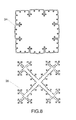
- FIG 18 An example of radar chaff cloud which uses this type of disperser is shown in Figure 18, while a cloud of radar chaff which contains a mix of space-filling and multilevel geometries of different sizes and geometries is described, in no way limiting the proposal in Figure 19.
- many of these techniques are employed.
- the space-filling and multilevel geometries could be cut and stamped in fine aluminium foil, copper or brass sheets.
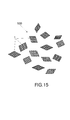
- An example of chaff cloud constructed with this technique is shown in Figure 15.
- use can also be made of any of the techniques available relating to printed circuits, be they rigid or flexible, printing and shielding a conductor pattern on a thin dielectric substrate.
- Said substrate can be made from a material offering low losses at a particular radar frequency, for example polyester, polyamide, paper, Mylar, fibreglass, Teflon, nylon, Dacron, orlon, rayon, Kapton ® , Cuclad ®, Rogers ®, or Aarlon ®.
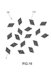
- chaff cloud (101) wherein the space-filling forms are supported on dielectric material (110) is shown in Figure 16.
- a substrate to support the conducting disperser can be convenient in many cases for diverse reasons: it provides additional air friction whereby the chaff remains in suspension a longer time, it prevents many dispersers from becoming intertwined and it can even be used to provide the disperser with a certain resistance to advance.
- An example of this can be seen in Figure 20.
- An arrow is shown as dielectric support so that the disperser adopts the desired orientation when descending. This can be used to improve the polarization state for the signal of the disperser since once the orientation is known with respect to the ground, the form of the disperser can be chosen to provide a greater response for a vertical, horizontal, circular polarization of the particular incident field).
- Fig.22 Another technique to improve air friction and so increase the time of suspension consists in making holes (124) in dielectric substrate (110) so that turbulence is created when the air flows through said holes.
- the dielectric support can be moulded in a mould material in the shape of a feather with several cuts (125) around the perimeter of said support.
- This technique is specially convenient when the disperser is supported by a dielectric leaf. Since the leaf covers the whole structure of the disperser, the holes can be made in the spaces that are present between the conducting parts of the space-filling and multilevel dispersers and also the aerodynamic behaviour of the original space-filling or multilevel geometry is recovered.
- Another encapsulation for the present invention consists in printing said space-filling and multilevel patterns by means of conducting ink on a fine and light dielectric support like for example paper.
- a fine and light dielectric support like for example paper.
- use can be made of a recyclable, bio-degradable or soluble paper, as well as plastic or a dielectric support.
- the benefits which could be obtained from this particular configuration could be the extremely cheap procedures for manufacturing said chaff, together with a minimum weight, a maximum packaging ratio and maximum respect for the environment.
- the decomposition properties of the material in the short and long term would provide convenient evanescent characteristics which can be of interest in multiple environments.
- a possible procedure for the production of the dispersers in accordance with the present invention would consist in braiding conducting fibres, or meshed conducting fibres in the form of a space-filling or multilevel curve in a light fabric (like for example wool, cotton, silk or linen) paper or another low-loss dielectric material.
- a chaff which appears and disappears can be obtained using any of the methods described in the literature like for example by applying on fibreglass or plastic like polyethylene terephalate separate meshes or coats of reducible metallic salt and an oxidizable metal; and by applying afterwards a liquid solution or a spray which contains a chemical which first oxidizes the metallic mesh and thereafter reduces the mesh which contains the reduced metallic salt.
- trihedral forms improve the backward reflection of incident waves and rays.
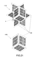
- Any of the preceding encapsulations can be used to arrange the dispersers spatially in the form of multilevel or space-filling trihedrons or compositions of trihedrons. Two particular examples of said encapsulations are shown (with no intention of limitation), in drawings (118) and (119) in Figure 21.
- a trihedron is formed with three space-filling dispersers on each of the three sides.
- eight trihedrons are joined to cover each of the eight semi-spaces in a system of Cartesian coordinates.
- an inhibited radar chaff can be implemented applying a diazo fluoride mesh consisting of a filament coated with sodium silicate, so that said chaff is more sensitive to ultraviolet light.
- chaff would become non-conducting and unable to transmit reflections toward the radar set. In this sense, radar chaff would become disabled as a reflector device for long exposure to sunlight or to an artificial ultraviolet light source.
Landscapes
- Engineering & Computer Science (AREA)
- Radar, Positioning & Navigation (AREA)
- Remote Sensing (AREA)
- Physics & Mathematics (AREA)
- Electromagnetism (AREA)
- Radar Systems Or Details Thereof (AREA)
Applications Claiming Priority (2)
| Application Number | Priority Date | Filing Date | Title |
|---|---|---|---|
| ES200102675 | 2001-11-30 | ||
| ES200102675A ES2190749B1 (es) | 2001-11-30 | 2001-11-30 | Dispersores "chaff" multinivel y/o "space-filling", contra radar. |
Publications (2)
| Publication Number | Publication Date |
|---|---|
| EP1317018A2 true EP1317018A2 (de) | 2003-06-04 |
| EP1317018A3 EP1317018A3 (de) | 2004-02-04 |
Family
ID=8499627
Family Applications (1)
| Application Number | Title | Priority Date | Filing Date |
|---|---|---|---|
| EP02380242A Withdrawn EP1317018A3 (de) | 2001-11-30 | 2002-11-27 | Raumfüllendes Anti-Radar und/oder Mehrebenen-Radarstörverteiler |
Country Status (3)
| Country | Link |
|---|---|
| US (1) | US6876320B2 (de) |
| EP (1) | EP1317018A3 (de) |
| ES (1) | ES2190749B1 (de) |
Cited By (8)
| Publication number | Priority date | Publication date | Assignee | Title |
|---|---|---|---|---|
| US7015868B2 (en) | 1999-09-20 | 2006-03-21 | Fractus, S.A. | Multilevel Antennae |
| US7148850B2 (en) | 2000-01-19 | 2006-12-12 | Fractus, S.A. | Space-filling miniature antennas |
| CN104900998A (zh) * | 2015-05-05 | 2015-09-09 | 西安电子科技大学 | 低剖面双极化基站天线 |
| US9899727B2 (en) | 2006-07-18 | 2018-02-20 | Fractus, S.A. | Multiple-body-configuration multimedia and smartphone multifunction wireless devices |
| CN112578352A (zh) * | 2020-12-08 | 2021-03-30 | 西安电子科技大学 | 基于fpga的箔条云雷达回波实时模拟方法 |
| CN114114195A (zh) * | 2021-12-16 | 2022-03-01 | 上海无线电设备研究所 | 一种箔条云回波仿真建模方法 |
| CN115856784A (zh) * | 2022-12-09 | 2023-03-28 | 中国人民解放军91550部队 | 一种机动化箔条幕协同布放方法 |
| CN119558158A (zh) * | 2024-11-15 | 2025-03-04 | 上海无线电设备研究所 | 一种基于三维粒子特效的机载箔条弹仿真方法 |
Families Citing this family (24)
| Publication number | Priority date | Publication date | Assignee | Title |
|---|---|---|---|---|
| AU2003215572A1 (en) | 2003-02-19 | 2004-09-09 | Fractus S.A. | Miniature antenna having a volumetric structure |
| DE102004049148A1 (de) | 2004-10-07 | 2006-04-13 | Rehau Ag + Co | Heizungselement auf einer polymeren Innenoberfläche eines Frontmoduls/Stoßfängers eines Kraftfahrzeuges in Wirkverbindung mit einer Radarsende- und - empfangseinheit |
| GB0606890D0 (en) * | 2006-04-05 | 2006-05-17 | Imp College Innovations Ltd | Fluid flow modification apparatus |
| DE102006017107A1 (de) * | 2006-04-10 | 2007-10-11 | Oerlikon Contraves Ag | Schutzeinrichtung und Schutzmaßnahme für eine Radaranlage |
| CN101060193A (zh) * | 2006-04-19 | 2007-10-24 | 旭硝子株式会社 | 汽车用高频玻璃天线及汽车用后窗玻璃板 |
| JP4832549B2 (ja) * | 2009-04-30 | 2011-12-07 | 原田工業株式会社 | 空間充填曲線を用いる車両用アンテナ装置 |
| US8648306B1 (en) | 2009-10-29 | 2014-02-11 | Capco, Inc. | Metamaterial dispersion |
| US9228785B2 (en) | 2010-05-04 | 2016-01-05 | Alexander Poltorak | Fractal heat transfer device |
| DE102010032458A1 (de) | 2010-06-11 | 2011-12-15 | Rheinmetall Waffe Munition Gmbh | Aktive Täuschkörper gegen Radarquellen sowie Verfahren zum Schutz von Objekten mit Hilfe derartiger Täuschkörper |
| DE102010047860A1 (de) | 2010-10-07 | 2012-04-12 | Rheinmetall Waffe Munition Gmbh | Täuschkörper zum Schutz von Objekten |
| US10014587B1 (en) * | 2011-12-08 | 2018-07-03 | The United States Of America As Represented By The Secretary Of The Navy | Retroreflecting chaff for laser defense |
| US9599441B2 (en) * | 2012-09-07 | 2017-03-21 | The United States Of America As Represented By The Secretary Of The Navy | Off-board influence system |
| EP3435751A1 (de) | 2012-10-01 | 2019-01-30 | Fractal Antenna Systems, Inc. | Strahlungsübertragung und leistungsregelung mit fraktalem metamaterial und plasmonik |
| US11268771B2 (en) | 2012-10-01 | 2022-03-08 | Fractal Antenna Systems, Inc. | Enhanced gain antenna systems employing fractal metamaterials |
| US9134465B1 (en) | 2012-11-03 | 2015-09-15 | Fractal Antenna Systems, Inc. | Deflective electromagnetic shielding |
| US11322850B1 (en) | 2012-10-01 | 2022-05-03 | Fractal Antenna Systems, Inc. | Deflective electromagnetic shielding |
| US10914534B2 (en) | 2012-10-01 | 2021-02-09 | Fractal Antenna Systems, Inc. | Directional antennas from fractal plasmonic surfaces |
| US10866034B2 (en) | 2012-10-01 | 2020-12-15 | Fractal Antenna Systems, Inc. | Superconducting wire and waveguides with enhanced critical temperature, incorporating fractal plasmonic surfaces |
| US20150048572A1 (en) * | 2013-03-29 | 2015-02-19 | American Pacific Plastic Fabricators, Inc. | Buoyant target with laser reflectivity |
| KR102175750B1 (ko) * | 2014-10-29 | 2020-11-06 | 삼성전자주식회사 | 안테나 장치 및 이를 구비하는 전자 장치 |
| US10830545B2 (en) | 2016-07-12 | 2020-11-10 | Fractal Heatsink Technologies, LLC | System and method for maintaining efficiency of a heat sink |
| US10731959B1 (en) * | 2018-01-12 | 2020-08-04 | Rockwell Collins, Inc. | Deployable active radar countermeasures |
| CN114167810B (zh) * | 2021-10-23 | 2022-11-25 | 西安电子科技大学 | 基于四轴插丝机的可控箔条云模型制作方法及控制系统 |
| CN114218798A (zh) * | 2021-12-16 | 2022-03-22 | 上海无线电设备研究所 | 一种箔条云模型反演方法 |
Citations (8)
| Publication number | Priority date | Publication date | Assignee | Title |
|---|---|---|---|---|
| EP0036239A2 (de) | 1980-03-17 | 1981-09-23 | Philips Norden AB | Vorrichtung zum Verteilen von Radardüppeln |
| US4471358A (en) | 1963-04-01 | 1984-09-11 | Raytheon Company | Re-entry chaff dart |
| US4597332A (en) | 1964-12-03 | 1986-07-01 | The United States Of America As Represented By The Secretary Of The Navy | Chaff dispenser for atmospheric re-entry |
| EP0246368A1 (de) | 1986-03-27 | 1987-11-25 | Chemring Limited | Düppelabwurfvorrichtung |
| US4763127A (en) | 1986-01-24 | 1988-08-09 | Tracor Aerospace Austin, Inc. | Fiber under foil chaff coil |
| US4976828A (en) | 1982-03-16 | 1990-12-11 | American Cyanamid Company | Chaff comprising metal coated fibers |
| US5087515A (en) | 1989-12-11 | 1992-02-11 | Advanced Technology Materials, Inc. | Chaff fiber comprising insulative coating thereon, and having an evanescent radar reflectance characteristic, and method of making the same |
| US5835682A (en) | 1991-03-22 | 1998-11-10 | The Secretary Of State For Defence In Her Britannic Majesty's Government Of The United Kingdom Of Great Britain And Northern Ireland | Dynamical system analyzer |
Family Cites Families (121)
| Publication number | Priority date | Publication date | Assignee | Title |
|---|---|---|---|---|
| US4167009A (en) * | 1963-08-08 | 1979-09-04 | Mcdonnell Douglas Corporation | Re-entry chaff |
| DE977840C (de) | 1963-10-30 | 1971-09-02 | Messerschmitt Boelkow Blohm | Dueppel aus Folie |
| US3521284A (en) | 1968-01-12 | 1970-07-21 | John Paul Shelton Jr | Antenna with pattern directivity control |
| US3622890A (en) | 1968-01-31 | 1971-11-23 | Matsushita Electric Industrial Co Ltd | Folded integrated antenna and amplifier |
| US3599214A (en) | 1969-03-10 | 1971-08-10 | New Tronics Corp | Automobile windshield antenna |
| US3683376A (en) | 1970-10-12 | 1972-08-08 | Joseph J O Pronovost | Radar antenna mount |
| US4638316A (en) * | 1973-10-30 | 1987-01-20 | The United States Of America As Represented By The Secretary Of The Navy | Radar reflecting electrolytes |
| US3910189A (en) * | 1974-03-25 | 1975-10-07 | Us Air Force | Deployment of conductors into the atmosphere |
| ES443806A1 (es) | 1974-12-25 | 1977-08-16 | Matsushita Electric Industrial Co Ltd | Perfeccionamientos introducidos en un aparato de antena paraun receptor de television o similar. |
| US3967276A (en) | 1975-01-09 | 1976-06-29 | Beam Guidance Inc. | Antenna structures having reactance at free end |
| US3969730A (en) | 1975-02-12 | 1976-07-13 | The United States Of America As Represented By The Secretary Of Transportation | Cross slot omnidirectional antenna |
| US4131893A (en) | 1977-04-01 | 1978-12-26 | Ball Corporation | Microstrip radiator with folded resonant cavity |
| JPS55147806A (en) | 1979-05-07 | 1980-11-18 | Matsushita Electric Ind Co Ltd | Rod antenna |
| HU182355B (en) | 1981-07-10 | 1983-12-28 | Budapesti Radiotechnikai Gyar | Aerial array for handy radio transceiver |
| DE3222584A1 (de) * | 1982-06-16 | 1983-12-22 | Diehl GmbH & Co, 8500 Nürnberg | Dipol-anordnung in einer huelse |
| US4471493A (en) | 1982-12-16 | 1984-09-11 | Gte Automatic Electric Inc. | Wireless telephone extension unit with self-contained dipole antenna |
| US4504834A (en) | 1982-12-22 | 1985-03-12 | Motorola, Inc. | Coaxial dipole antenna with extended effective aperture |
| DE3302876A1 (de) | 1983-01-28 | 1984-08-02 | Robert Bosch Gmbh, 7000 Stuttgart | Dipolantenne fuer tragbare funkgeraete |
| US4584709A (en) | 1983-07-06 | 1986-04-22 | Motorola, Inc. | Homotropic antenna system for portable radio |
| US4839660A (en) | 1983-09-23 | 1989-06-13 | Orion Industries, Inc. | Cellular mobile communication antenna |
| DE3337941A1 (de) * | 1983-10-19 | 1985-05-09 | Bayer Ag, 5090 Leverkusen | Passive radarreflektoren |
| US4571595A (en) | 1983-12-05 | 1986-02-18 | Motorola, Inc. | Dual band transceiver antenna |
| US4730195A (en) | 1985-07-01 | 1988-03-08 | Motorola, Inc. | Shortened wideband decoupled sleeve dipole antenna |
| US5619205A (en) * | 1985-09-25 | 1997-04-08 | The United States Of America As Represented By The Secretary Of The Army | Microarc chaff |
| JPS63173934U (de) | 1987-04-30 | 1988-11-11 | ||
| US4894663A (en) | 1987-11-16 | 1990-01-16 | Motorola, Inc. | Ultra thin radio housing with integral antenna |
| GB2215136A (en) * | 1988-02-10 | 1989-09-13 | Ronald Cecil Hutchins | Broadsword anti-radar foil |
| US4857939A (en) | 1988-06-03 | 1989-08-15 | Alliance Research Corporation | Mobile communications antenna |
| US5227804A (en) | 1988-07-05 | 1993-07-13 | Nec Corporation | Antenna structure used in portable radio device |
| US4847629A (en) | 1988-08-03 | 1989-07-11 | Alliance Research Corporation | Retractable cellular antenna |
| JP2737942B2 (ja) | 1988-08-22 | 1998-04-08 | ソニー株式会社 | 受信機 |
| KR920002439B1 (ko) | 1988-08-31 | 1992-03-24 | 삼성전자 주식회사 | 휴대용 무선전화기의 슬로트 안테나 장치 |
| US5218370A (en) | 1990-12-10 | 1993-06-08 | Blaese Herbert R | Knuckle swivel antenna for portable telephone |
| AU1346592A (en) | 1991-01-24 | 1992-08-27 | Rdi Electronics, Inc. | Broadband antenna |
| US5200756A (en) | 1991-05-03 | 1993-04-06 | Novatel Communications Ltd. | Three dimensional microstrip patch antenna |
| US5227808A (en) | 1991-05-31 | 1993-07-13 | The United States Of America As Represented By The Secretary Of The Air Force | Wide-band L-band corporate fed antenna for space based radars |
| JP2653277B2 (ja) | 1991-06-27 | 1997-09-17 | 三菱電機株式会社 | 携帯無線通信装置 |
| GB2257838B (en) | 1991-07-13 | 1995-06-14 | Technophone Ltd | Retractable antenna |
| US5138328A (en) | 1991-08-22 | 1992-08-11 | Motorola, Inc. | Integral diversity antenna for a laptop computer |
| JP3168219B2 (ja) | 1991-10-31 | 2001-05-21 | 原田工業株式会社 | 無線電話機用の極超短波アンテナ |
| JPH05335826A (ja) | 1991-11-18 | 1993-12-17 | Motorola Inc | 通信装置用の内蔵アンテナ |
| US5347291A (en) | 1991-12-05 | 1994-09-13 | Moore Richard L | Capacitive-type, electrically short, broadband antenna and coupling systems |
| US5212488A (en) * | 1992-01-21 | 1993-05-18 | Konotchick John A | Ellipsoidal chaff |
| JP2558571B2 (ja) | 1992-03-23 | 1996-11-27 | 株式会社ヨコオ | ロッドアンテナ |
| US5373300A (en) | 1992-05-21 | 1994-12-13 | International Business Machines Corporation | Mobile data terminal with external antenna |
| US5214434A (en) | 1992-05-15 | 1993-05-25 | Hsu Wan C | Mobile phone antenna with improved impedance-matching circuit |
| JPH05347507A (ja) | 1992-06-12 | 1993-12-27 | Junkosha Co Ltd | アンテナ |
| JPH0697713A (ja) | 1992-07-28 | 1994-04-08 | Mitsubishi Electric Corp | アンテナ |
| US5451968A (en) | 1992-11-19 | 1995-09-19 | Solar Conversion Corp. | Capacitively coupled high frequency, broad-band antenna |
| JPH06204908A (ja) | 1993-01-07 | 1994-07-22 | Nippon Motorola Ltd | 無線機用アンテナ |
| US5493702A (en) | 1993-04-05 | 1996-02-20 | Crowley; Robert J. | Antenna transmission coupling arrangement |
| GB9309368D0 (en) | 1993-05-06 | 1993-06-16 | Ncr Int Inc | Antenna apparatus |
| US5422651A (en) | 1993-10-13 | 1995-06-06 | Chang; Chin-Kang | Pivotal structure for cordless telephone antenna |
| US5841403A (en) | 1995-04-25 | 1998-11-24 | Norand Corporation | Antenna means for hand-held radio devices |
| ES2112163B1 (es) * | 1995-05-19 | 1998-11-16 | Univ Catalunya Politecnica | Antenas fractales o multifractales. |
| JPH11506282A (ja) | 1995-06-02 | 1999-06-02 | エリクソン インコーポレイテッド | 多バンド印刷モノポールアンテナ |
| US6476766B1 (en) | 1997-11-07 | 2002-11-05 | Nathan Cohen | Fractal antenna ground counterpoise, ground planes, and loading elements and microstrip patch antennas with fractal structure |
| US6127977A (en) | 1996-11-08 | 2000-10-03 | Cohen; Nathan | Microstrip patch antenna with fractal structure |
| ES2236745T3 (es) | 1995-08-09 | 2005-07-16 | Fractal Antenna Systems Inc. | Antenas resonadores y elementos de carga fractales. |
| US6104349A (en) | 1995-08-09 | 2000-08-15 | Cohen; Nathan | Tuning fractal antennas and fractal resonators |
| US6452553B1 (en) | 1995-08-09 | 2002-09-17 | Fractal Antenna Systems, Inc. | Fractal antennas and fractal resonators |
| JP3289572B2 (ja) | 1995-09-19 | 2002-06-10 | 株式会社村田製作所 | チップアンテナ |
| US5872546A (en) | 1995-09-27 | 1999-02-16 | Ntt Mobile Communications Network Inc. | Broadband antenna using a semicircular radiator |
| USH1631H (en) | 1995-10-27 | 1997-02-04 | United States Of America | Method of fabricating radar chaff |
| JP3166589B2 (ja) | 1995-12-06 | 2001-05-14 | 株式会社村田製作所 | チップアンテナ |
| US5898404A (en) | 1995-12-22 | 1999-04-27 | Industrial Technology Research Institute | Non-coplanar resonant element printed circuit board antenna |
| JP3319268B2 (ja) | 1996-02-13 | 2002-08-26 | 株式会社村田製作所 | 表面実装型アンテナおよびこれを用いた通信機 |
| US5684672A (en) | 1996-02-20 | 1997-11-04 | International Business Machines Corporation | Laptop computer with an integrated multi-mode antenna |
| US5821907A (en) | 1996-03-05 | 1998-10-13 | Research In Motion Limited | Antenna for a radio telecommunications device |
| DE59708915D1 (de) | 1996-03-13 | 2003-01-23 | Ascom Systec Ag Maegenwil | Flache dreidimensionale Antenne |
| SE507077C2 (sv) | 1996-05-17 | 1998-03-23 | Allgon Ab | Antennanordning för en portabel radiokommunikationsanordning |
| AU2748797A (en) | 1996-06-05 | 1998-01-05 | Intercell Wireless Corporation | Dual resonance antenna for portable telephone |
| US5990838A (en) | 1996-06-12 | 1999-11-23 | 3Com Corporation | Dual orthogonal monopole antenna system |
| EP1345283A1 (de) | 1996-06-20 | 2003-09-17 | Kabushiki Kaisha Yokowo (also trading as Yokowo Co., Ltd.) | Antenne |
| US5966098A (en) | 1996-09-18 | 1999-10-12 | Research In Motion Limited | Antenna system for an RF data communications device |
| JPH1098322A (ja) | 1996-09-20 | 1998-04-14 | Murata Mfg Co Ltd | チップアンテナ及びアンテナ装置 |
| FI113212B (fi) | 1997-07-08 | 2004-03-15 | Nokia Corp | Usean taajuusalueen kaksoisresonanssiantennirakenne |
| SE511501C2 (sv) | 1997-07-09 | 1999-10-11 | Allgon Ab | Kompakt antennanordning |
| SE509232C2 (sv) | 1997-07-09 | 1998-12-21 | Allgon Ab | Handportabel telefon med strålningsabsorberande anordning |
| GB2330951B (en) | 1997-11-04 | 2002-09-18 | Nokia Mobile Phones Ltd | Antenna |
| SE511131C2 (sv) | 1997-11-06 | 1999-08-09 | Ericsson Telefon Ab L M | Portabel elektronisk kommunikationsanordning med flerbandigt antennsystem |
| WO1999027608A1 (en) | 1997-11-22 | 1999-06-03 | Nathan Cohen | Cylindrical conformable antenna on a planar substrate |
| JP3296276B2 (ja) | 1997-12-11 | 2002-06-24 | 株式会社村田製作所 | チップアンテナ |
| WO2001033665A1 (en) | 1999-11-04 | 2001-05-10 | Rangestar Wireless, Inc. | Single or dual band parasitic antenna assembly |
| FI113213B (fi) | 1998-01-21 | 2004-03-15 | Filtronic Lk Oy | Tasoantenni |
| SE513055C2 (sv) | 1998-04-24 | 2000-06-26 | Intenna Technology Ab | Flerbandsantennanordning |
| US6031505A (en) | 1998-06-26 | 2000-02-29 | Research In Motion Limited | Dual embedded antenna for an RF data communications device |
| US6353443B1 (en) | 1998-07-09 | 2002-03-05 | Telefonaktiebolaget Lm Ericsson (Publ) | Miniature printed spiral antenna for mobile terminals |
| FR2784506A1 (fr) | 1998-10-12 | 2000-04-14 | Socapex Amphenol | Antenne a plaque |
| FI105061B (fi) | 1998-10-30 | 2000-05-31 | Lk Products Oy | Kahden resonanssitaajuuden tasoantenni |
| DE69934965T2 (de) | 1998-12-22 | 2007-12-20 | Nokia Corp. | Zwei-Frequenzbereich-Antennensystem für einen tragbaren Telefonhandapparat sowie ein solcher tragbarer Telefonhandapparat |
| FI105421B (fi) | 1999-01-05 | 2000-08-15 | Filtronic Lk Oy | Tasomainen kahden taajuuden antenni ja tasoantennilla varustettu radiolaite |
| NL1011421C2 (nl) | 1999-03-02 | 2000-09-05 | Tno | Volumetrisch phased array antenne systeem. |
| DE19929689A1 (de) | 1999-06-29 | 2001-01-11 | Siemens Ag | Integrierbare Dualband-Antenne |
| AU6331600A (en) | 1999-07-23 | 2001-02-13 | Avantego Ab | Antenna arrangement |
| AU6210700A (en) | 1999-08-18 | 2001-03-13 | Ericsson Inc. | A dual band bowtie/meander antenna |
| FI112982B (fi) | 1999-08-25 | 2004-02-13 | Filtronic Lk Oy | Tasoantennirakenne |
| US6218991B1 (en) | 1999-08-27 | 2001-04-17 | Mohamed Sanad | Compact planar inverted F antenna |
| FI114587B (fi) | 1999-09-10 | 2004-11-15 | Filtronic Lk Oy | Tasoantennirakenne |
| EP1223637B1 (de) * | 1999-09-20 | 2005-03-30 | Fractus, S.A. | Mehrebenenantenne |
| GB2355114B (en) | 1999-09-30 | 2004-03-24 | Harada Ind | Dual-band microstrip antenna |
| SE522522C2 (sv) | 1999-10-04 | 2004-02-10 | Smarteq Wireless Ab | Antennorgan |
| WO2001031739A1 (en) | 1999-10-08 | 2001-05-03 | Antennas America, Inc. | Compact microstrip antenna for gps applications |
| GB2355116B (en) | 1999-10-08 | 2003-10-08 | Nokia Mobile Phones Ltd | An antenna assembly and method of construction |
| WO2001028035A1 (en) | 1999-10-12 | 2001-04-19 | Arc Wireless Solutions, Inc. | Compact dual narrow band microstrip antenna |
| FI112984B (fi) | 1999-10-20 | 2004-02-13 | Filtronic Lk Oy | Laitteen sisäinen antenni |
| FI114586B (fi) | 1999-11-01 | 2004-11-15 | Filtronic Lk Oy | Tasoantenni |
| FR2801139B1 (fr) | 1999-11-12 | 2001-12-21 | France Telecom | Antenne imprimee bi-bande |
| SE517564C2 (sv) | 1999-11-17 | 2002-06-18 | Allgon Ab | Antennanordning för en bärbar radiokommunikationsanordning, bärbar radiokommunikationsanordning med sådan antennanordning och metod för att driva nämnda radiokommunikationsanordning |
| SE516474C2 (sv) | 1999-11-19 | 2002-01-22 | Allgon Ab | Antennanordning och kommunikationsanordning innefattande en sådan antennanordning |
| DE19958119A1 (de) | 1999-12-02 | 2001-06-07 | Siemens Ag | Mobiles Kommunikationsendgerät |
| EP1592083B1 (de) * | 2000-01-19 | 2013-04-03 | Fractus, S.A. | raumfüllende miniaturantennen |
| US6218992B1 (en) | 2000-02-24 | 2001-04-17 | Ericsson Inc. | Compact, broadband inverted-F antennas with conductive elements and wireless communicators incorporating same |
| WO2001069710A1 (en) | 2000-03-15 | 2001-09-20 | Matsushita Electric Industrial Co., Ltd. | Multilayer electronic part, multilayer antenna duplexer, and communication apparatus |
| US6329951B1 (en) | 2000-04-05 | 2001-12-11 | Research In Motion Limited | Electrically connected multi-feed antenna system |
| US6329954B1 (en) | 2000-04-14 | 2001-12-11 | Receptec L.L.C. | Dual-antenna system for single-frequency band |
| WO2001080354A1 (en) | 2000-04-14 | 2001-10-25 | Rangestar Wireless, Inc. | Compact dual frequency antenna with multiple polarization |
| US6452549B1 (en) | 2000-05-02 | 2002-09-17 | Bae Systems Information And Electronic Systems Integration Inc | Stacked, multi-band look-through antenna |
| US20020109633A1 (en) | 2001-02-14 | 2002-08-15 | Steven Ow | Low cost microstrip antenna |
| US6429816B1 (en) | 2001-05-04 | 2002-08-06 | Harris Corporation | Spatially orthogonal signal distribution and support architecture for multi-beam phased array antenna |
| WO2002096166A1 (en) | 2001-05-18 | 2002-11-28 | Corporation For National Research Initiatives | Radio frequency microelectromechanical systems (mems) devices on low-temperature co-fired ceramic (ltcc) substrates |
-
2001
- 2001-11-30 ES ES200102675A patent/ES2190749B1/es not_active Expired - Fee Related
-
2002
- 2002-11-26 US US10/305,788 patent/US6876320B2/en not_active Expired - Fee Related
- 2002-11-27 EP EP02380242A patent/EP1317018A3/de not_active Withdrawn
Patent Citations (8)
| Publication number | Priority date | Publication date | Assignee | Title |
|---|---|---|---|---|
| US4471358A (en) | 1963-04-01 | 1984-09-11 | Raytheon Company | Re-entry chaff dart |
| US4597332A (en) | 1964-12-03 | 1986-07-01 | The United States Of America As Represented By The Secretary Of The Navy | Chaff dispenser for atmospheric re-entry |
| EP0036239A2 (de) | 1980-03-17 | 1981-09-23 | Philips Norden AB | Vorrichtung zum Verteilen von Radardüppeln |
| US4976828A (en) | 1982-03-16 | 1990-12-11 | American Cyanamid Company | Chaff comprising metal coated fibers |
| US4763127A (en) | 1986-01-24 | 1988-08-09 | Tracor Aerospace Austin, Inc. | Fiber under foil chaff coil |
| EP0246368A1 (de) | 1986-03-27 | 1987-11-25 | Chemring Limited | Düppelabwurfvorrichtung |
| US5087515A (en) | 1989-12-11 | 1992-02-11 | Advanced Technology Materials, Inc. | Chaff fiber comprising insulative coating thereon, and having an evanescent radar reflectance characteristic, and method of making the same |
| US5835682A (en) | 1991-03-22 | 1998-11-10 | The Secretary Of State For Defence In Her Britannic Majesty's Government Of The United Kingdom Of Great Britain And Northern Ireland | Dynamical system analyzer |
Cited By (24)
| Publication number | Priority date | Publication date | Assignee | Title |
|---|---|---|---|---|
| US10056682B2 (en) | 1999-09-20 | 2018-08-21 | Fractus, S.A. | Multilevel antennae |
| US7015868B2 (en) | 1999-09-20 | 2006-03-21 | Fractus, S.A. | Multilevel Antennae |
| US7397431B2 (en) | 1999-09-20 | 2008-07-08 | Fractus, S.A. | Multilevel antennae |
| US7123208B2 (en) | 1999-09-20 | 2006-10-17 | Fractus, S.A. | Multilevel antennae |
| US9761934B2 (en) | 1999-09-20 | 2017-09-12 | Fractus, S.A. | Multilevel antennae |
| US7394432B2 (en) | 1999-09-20 | 2008-07-01 | Fractus, S.A. | Multilevel antenna |
| US7505007B2 (en) | 1999-09-20 | 2009-03-17 | Fractus, S.A. | Multi-level antennae |
| US7148850B2 (en) | 2000-01-19 | 2006-12-12 | Fractus, S.A. | Space-filling miniature antennas |
| US10355346B2 (en) | 2000-01-19 | 2019-07-16 | Fractus, S.A. | Space-filling miniature antennas |
| US7202822B2 (en) | 2000-01-19 | 2007-04-10 | Fractus, S.A. | Space-filling miniature antennas |
| US7164386B2 (en) | 2000-01-19 | 2007-01-16 | Fractus, S.A. | Space-filling miniature antennas |
| US9899727B2 (en) | 2006-07-18 | 2018-02-20 | Fractus, S.A. | Multiple-body-configuration multimedia and smartphone multifunction wireless devices |
| US11031677B2 (en) | 2006-07-18 | 2021-06-08 | Fractus, S.A. | Multiple-body-configuration multimedia and smartphone multifunction wireless devices |
| US10644380B2 (en) | 2006-07-18 | 2020-05-05 | Fractus, S.A. | Multiple-body-configuration multimedia and smartphone multifunction wireless devices |
| US11349200B2 (en) | 2006-07-18 | 2022-05-31 | Fractus, S.A. | Multiple-body-configuration multimedia and smartphone multifunction wireless devices |
| US11735810B2 (en) | 2006-07-18 | 2023-08-22 | Fractus, S.A. | Multiple-body-configuration multimedia and smartphone multifunction wireless devices |
| US12095149B2 (en) | 2006-07-18 | 2024-09-17 | Fractus, S.A. | Multiple-body-configuration multimedia and smartphone multifunction wireless devices |
| CN104900998A (zh) * | 2015-05-05 | 2015-09-09 | 西安电子科技大学 | 低剖面双极化基站天线 |
| CN104900998B (zh) * | 2015-05-05 | 2018-05-15 | 西安电子科技大学 | 低剖面双极化基站天线 |
| CN112578352A (zh) * | 2020-12-08 | 2021-03-30 | 西安电子科技大学 | 基于fpga的箔条云雷达回波实时模拟方法 |
| CN112578352B (zh) * | 2020-12-08 | 2023-06-30 | 西安电子科技大学 | 基于fpga的箔条云雷达回波实时模拟方法 |
| CN114114195A (zh) * | 2021-12-16 | 2022-03-01 | 上海无线电设备研究所 | 一种箔条云回波仿真建模方法 |
| CN115856784A (zh) * | 2022-12-09 | 2023-03-28 | 中国人民解放军91550部队 | 一种机动化箔条幕协同布放方法 |
| CN119558158A (zh) * | 2024-11-15 | 2025-03-04 | 上海无线电设备研究所 | 一种基于三维粒子特效的机载箔条弹仿真方法 |
Also Published As
| Publication number | Publication date |
|---|---|
| EP1317018A3 (de) | 2004-02-04 |
| ES2190749A1 (es) | 2003-08-01 |
| US6876320B2 (en) | 2005-04-05 |
| ES2190749B1 (es) | 2004-06-16 |
| US20030137442A1 (en) | 2003-07-24 |
Similar Documents
| Publication | Publication Date | Title |
|---|---|---|
| US6876320B2 (en) | Anti-radar space-filling and/or multilevel chaff dispersers | |
| US5208603A (en) | Frequency selective surface (FSS) | |
| Dewan et al. | Artificial magnetic conductor for various antenna applications: An overview | |
| Anwar et al. | Frequency selective surfaces: A review | |
| EP2198480B1 (de) | Polyeder-antenne und zugehörige verfahren | |
| US6300914B1 (en) | Fractal loop antenna | |
| Huang et al. | Tri-band frequency selective surface with circular ring elements | |
| EP2573864B1 (de) | Künstliche mikrostruktur und künstliches elektromagnetisches material damit | |
| US8593349B2 (en) | Miniature antenna having a volumetric structure | |
| WO2007148097A2 (en) | Compact antenna | |
| WO2003038946A1 (en) | Broadband starfish antenna and array thereof | |
| WO2002095874A1 (en) | Fractal cross slot antenna | |
| EP2629367B1 (de) | Flache wellenförmige Ultrabreitband-Schlitzantennengruppe | |
| CN119171084B (zh) | 基于c波段卫星通信的rcs带内缩减圆极化超表面天线 | |
| US7236139B2 (en) | Low backscatter polymer antenna with graded conductivity | |
| Hossain et al. | A compact low-cost and lightweight 3-D printed horn antenna for UWB systems | |
| Ahmed et al. | Analysis and design of 3-D printed fractal triangular antenna for wireless communications applications | |
| Machado et al. | Comparison of FSS topologies for maximising the bandwidth of ultra-thin microwave absorbers | |
| Chomtong et al. | Miniaturized multiband EBG reflector using DICPW structure for wireless communication systems | |
| EP0527714B1 (de) | Hohlraumantenne | |
| Kaur et al. | Radar cross section reduction techniques using metamaterials | |
| Joshi et al. | Introduction to 3d printing of sensors, actuators, and antennas for low-cost product manufacturing | |
| Joy et al. | Radar Cross-Section (RCS) Estimation and Reduction | |
| Haddad et al. | Design of high gain novel dielectric resonator antenna array for 24 GHz short range radar systems | |
| Sabban | Wearable Compact Fractal Antennas for 5G and Medical Systems |
Legal Events
| Date | Code | Title | Description |
|---|---|---|---|
| PUAI | Public reference made under article 153(3) epc to a published international application that has entered the european phase |
Free format text: ORIGINAL CODE: 0009012 |
|
| AK | Designated contracting states |
Designated state(s): AT BE BG CH CY CZ DE DK EE ES FI FR GB GR IE IT LI LU MC NL PT SE SK TR |
|
| AX | Request for extension of the european patent |
Extension state: AL LT LV MK RO SI |
|
| PUAL | Search report despatched |
Free format text: ORIGINAL CODE: 0009013 |
|
| AK | Designated contracting states |
Kind code of ref document: A3 Designated state(s): AT BE BG CH CY CZ DE DK EE ES FI FR GB GR IE IT LI LU MC NL PT SE SK TR |
|
| AX | Request for extension of the european patent |
Extension state: AL LT LV MK RO SI |
|
| RIC1 | Information provided on ipc code assigned before grant |
Ipc: 7H 01Q 15/18 B Ipc: 7H 01Q 15/14 A |
|
| AKX | Designation fees paid | ||
| REG | Reference to a national code |
Ref country code: DE Ref legal event code: 8566 |
|
| STAA | Information on the status of an ep patent application or granted ep patent |
Free format text: STATUS: THE APPLICATION IS DEEMED TO BE WITHDRAWN |
|
| 18D | Application deemed to be withdrawn |
Effective date: 20040805 |