EP1318533A1 - Procédé pour établir l'état d'usure des contacts d'un disjonctreur - Google Patents
Procédé pour établir l'état d'usure des contacts d'un disjonctreur Download PDFInfo
- Publication number
- EP1318533A1 EP1318533A1 EP01811191A EP01811191A EP1318533A1 EP 1318533 A1 EP1318533 A1 EP 1318533A1 EP 01811191 A EP01811191 A EP 01811191A EP 01811191 A EP01811191 A EP 01811191A EP 1318533 A1 EP1318533 A1 EP 1318533A1
- Authority
- EP
- European Patent Office
- Prior art keywords
- current
- switching
- calculated
- arc
- chamber element
- Prior art date
- Legal status (The legal status is an assumption and is not a legal conclusion. Google has not performed a legal analysis and makes no representation as to the accuracy of the status listed.)
- Withdrawn
Links
Images



Classifications
-
- H—ELECTRICITY
- H01—ELECTRIC ELEMENTS
- H01H—ELECTRIC SWITCHES; RELAYS; SELECTORS; EMERGENCY PROTECTIVE DEVICES
- H01H1/00—Contacts
- H01H1/0015—Means for testing or for inspecting contacts, e.g. wear indicator
-
- H—ELECTRICITY
- H01—ELECTRIC ELEMENTS
- H01H—ELECTRIC SWITCHES; RELAYS; SELECTORS; EMERGENCY PROTECTIVE DEVICES
- H01H71/00—Details of the protective switches or relays covered by groups H01H73/00 - H01H83/00
- H01H71/04—Means for indicating condition of the switching device
- H01H2071/044—Monitoring, detection or measuring systems to establish the end of life of the switching device, can also contain other on-line monitoring systems, e.g. for detecting mechanical failures
Definitions
- the invention is based on a method for determining the through Arcing caused by a circuit breaker after the Preamble of claim 1.
- the temporal Dependency of an arc current flowing during a switching operation is the current one State of the switch calculated in a monitoring system.
- the invention solves the problem Specify the method of the type mentioned, which the state of a Circuit breaker detected with high accuracy, and so a very precise statement about whose remaining life enables.
- a monitoring system initially at least the following data is supplied: geometry parameters of one of the combustion effects of the Arc exposed part of an element of a switch chamber of the switch, the Values determine the remaining life of the switch and from which the volume of the arc exposed part is calculated, the density of the interrupter element Time from which the switching chamber element is exposed to the action of the arc a the erosion of the switching chamber element as a function of the arc current density representing burnup characteristics and a determined during the switching process Current-time diagram (i (t) diagram).
- the monitoring system determines from the i (t) diagram and the time the size and duration of that Switching chamber element loading arc current, determined from this and from the Burn-up characteristic is the mass burn-up caused by the switching process Switch chamber element, by summing this and that in all the previous ones Switching operations determine the total mass burnup of the Switch chamber element fixed and determined with the help of the density of the Switching chamber element the volume of the part exposed to arcing and from it the current value of at least one of the geometry parameters after the switching process.
- the inventive method is characterized by high accuracy and great Redundancy off if several are exposed to the burning effects of the arc Switching chamber elements are each assigned a geometry parameter.
- Geometric parameters are advantageously the inner radius of a contact tulip, the height of a when the contact tulip burns down on its inner surface, the length of the truncated cone of a contact pin interacting with the tulip, the inner radius of one Auxiliary nozzle or the inner radius of a main nozzle.
- the burn is already far an alarm message is issued as soon as the current value of the Geometry parameters or the value of one of several of the geometry parameters derived state parameters of the contact arrangement exceeds a limit value.
- the most important for an exact remaining life prediction and each of them Switching chamber elements own combustion characteristic is advantageously by a polynomial approximated.
- the corresponding polynomial coefficients can be empirically derived from the Mass burn and the load on the interrupter element can be determined.
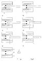
- the in Fig.1 Switch chamber of a circuit breaker is shown in a highly simplified manner in the area of their Extinguishing zone is formed axially symmetrical and has a current-carrying contact arrangement with a fixed tulip contact f and a movable one Contact pin s and an insulating material - such as polytetrafluoroethylene - consisting of one Auxiliary nozzle h and a main nozzle d.
- an insulating material - such as polytetrafluoroethylene - consisting of one Auxiliary nozzle h and a main nozzle d.
- Contact tulip f in addition to Contact tulip f also has a fixed design for the auxiliary nozzle h and the main nozzle d.
- the contact tulip f and the two nozzles h and d are designed to be movable and the contact pin s is fixed or, if appropriate is also designed to be movable.
- the contact tulip can also have a pin shape.
- the auxiliary nozzle h or the main nozzle d or both nozzles omitted. It is particularly important that there is a shift between the two Contacts f and s form an arc, which at least on one of these two Switching chamber elements or on one of the further provided, if applicable Switching chamber elements h and d erosion and thus the service life of the switch determining wear.
- the position of the tip of the contact pin f in the position a) is defined as the reference point z 0 of the stroke coordinate.
- the position g) defines the position z 6 of the tip of the contact pin s at the time the current is extinguished.
- the tip of the contact pin s is defined by position coordinates z 1 , z 2 , z 3 , z 4 and z 5 .
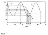
- FIG. 2 shows the assigned z (t) diagram with the path or stroke coordinate z of the switching pin s and the time coordinate t as well as the assigned i (t) diagram with the arc current i flowing during the switching-off process as one and the time t shown as another coordinate.
- the position g) (position coordinate z 6 ) happens to be identical to the switch-off position of the switch (contact pin s can no longer be moved downward along the path coordinate z).
- position z 6 shifts upwards.
- FIG. 3 shows analog positions a) to g) of the contact pin s of the same switch shortly before a necessary revision, that is to say if the switching arcs have caused the switching chamber elements f, s, h, d to burn up after switching operations under power.
- 4 shows the associated z (t) diagram of the tip of the contact pin s and a possible i (t) diagram.
- the same current curve was chosen. It should be noted that even when burned out, the position of the pen tip in the switched-on position is defined as the zero point of the stroke coordinate.
- the coordinates z 1 , z 2 , z 3 , z 4 and z 5 have shifted due to the erosion.
- position coordinate time a) z 0 t 0 Fully switched on position, time of triggering the pen movement ( coil signal) b) z 1 t 1
- the following definitions apply, whereby the indices f, s, h, d, refer in turn to the switching chamber elements designated with them:
- the powers p f , p s , p h and p d are usually in the interval between 1 and 2.
- ⁇ f , ⁇ s , ⁇ h and ⁇ d in turn mean the densities of the material of the contact tulip f, the contact pin s, the auxiliary nozzle h and the main nozzle d.
- tulip contacts burn both internally in a cylindrical manner and on the side facing the arc zone at an angle ⁇ f .
- the end of the service life is reached when the inside diameter of the tulip becomes larger than the outside diameter of the pin, or when the contact overlap, which is also influenced by the angle a f in addition to the pin burn-off, becomes smaller than a predetermined limit value when switched on.
- this limit is 0.
- the limit must be selected so that there is still enough time to commutate the current.
- a f, k can be calculated from this.
- the auxiliary nozzle burns cylindrically inside and that for the Burning effective length remains constant.
- switches that are operated at low voltages have the Switch on usually a comparatively short arc duration.
- the caused by it Burning phenomena are minor and can be neglected.
- the parameters I eff , I DC , f, t e and ⁇ can be determined from the measurement of time and current of individual points (eg current peaks or current zero crossings), which significantly reduces the amount of data.
- the burn-up characteristics are determined separately and in advance of the end of life. Precise measurements of the masses of the interrupter elements must be carried out before and after switching operations. Such measurements are typically taken during laboratory tests, but can also be carried out on site. Due to weighing uncertainties, the data from several switching operations can often be summarized. If the current densities between the individual switching processes do not differ significantly, S f , S s , S h and S d as the sum of all individual loads, ⁇ m f , ⁇ m s , ⁇ m h and ⁇ m d as the total mass burn-up of all switching processes and J f , J s , J h and J d are interpreted as the mean of the individual current densities.
Landscapes
- Circuit Breakers (AREA)
Priority Applications (1)
| Application Number | Priority Date | Filing Date | Title |
|---|---|---|---|
| EP01811191A EP1318533A1 (fr) | 2001-12-07 | 2001-12-07 | Procédé pour établir l'état d'usure des contacts d'un disjonctreur |
Applications Claiming Priority (1)
| Application Number | Priority Date | Filing Date | Title |
|---|---|---|---|
| EP01811191A EP1318533A1 (fr) | 2001-12-07 | 2001-12-07 | Procédé pour établir l'état d'usure des contacts d'un disjonctreur |
Publications (1)
| Publication Number | Publication Date |
|---|---|
| EP1318533A1 true EP1318533A1 (fr) | 2003-06-11 |
Family
ID=8184294
Family Applications (1)
| Application Number | Title | Priority Date | Filing Date |
|---|---|---|---|
| EP01811191A Withdrawn EP1318533A1 (fr) | 2001-12-07 | 2001-12-07 | Procédé pour établir l'état d'usure des contacts d'un disjonctreur |
Country Status (1)
| Country | Link |
|---|---|
| EP (1) | EP1318533A1 (fr) |
Cited By (8)
| Publication number | Priority date | Publication date | Assignee | Title |
|---|---|---|---|---|
| WO2008000105A1 (fr) * | 2006-06-26 | 2008-01-03 | Abb Technology Ag | Procédé pour déterminer l'érosion des contacts sur un disjoncteur à haut pouvoir de coupure |
| EP2328159A1 (fr) * | 2009-11-25 | 2011-06-01 | ABB Research Ltd. | Procédé et dispositif de détermination d'une usure d'un élément de contact |
| DE102011080826A1 (de) * | 2011-08-11 | 2013-02-14 | Siemens Aktiengesellschaft | Verfahren zum Ermitteln der Lichtbogenleistung eines Schalters, Verfahren zum Auslösen eines Schalters anhand der Lichtbogenleistung und Verfahren zur Ermittlung der Belastung der Kontakte eines Schalters anhand der Lichtbogenenergie |
| CN111933459A (zh) * | 2020-07-20 | 2020-11-13 | 西安热工研究院有限公司 | 一种利用电弧功率检测断路器触头电气磨损状态的方法 |
| US20220004181A1 (en) * | 2018-10-10 | 2022-01-06 | Siemens Aktiengesellschaft | Remaining service life prediction for switches |
| CN114757068A (zh) * | 2022-03-28 | 2022-07-15 | 清华大学 | 用于单相接地故障的定子铁心电弧烧损的建模分析方法 |
| CN116413589A (zh) * | 2021-12-31 | 2023-07-11 | 西安交通大学 | 断路器的电寿命预测方法和设备 |
| CN119419107A (zh) * | 2025-01-03 | 2025-02-11 | 浙江西屋电气股份有限公司 | 一种塑壳断路器及其塑壳断路器电寿命预测方法、介质、设备 |
Citations (2)
| Publication number | Priority date | Publication date | Assignee | Title |
|---|---|---|---|---|
| DE19923362A1 (de) * | 1999-05-21 | 2000-11-23 | Abb Patent Gmbh | Verfahren zur Bewertung des Kontaktzustandes eines Leistungsschalters |
| EP1120801A2 (fr) * | 2000-01-29 | 2001-08-01 | MASCHINENFABRIK REINHAUSEN GmbH | Méthode pour surveiller l' usure des contacts d' un interrupteur à gradins |
-
2001
- 2001-12-07 EP EP01811191A patent/EP1318533A1/fr not_active Withdrawn
Patent Citations (2)
| Publication number | Priority date | Publication date | Assignee | Title |
|---|---|---|---|---|
| DE19923362A1 (de) * | 1999-05-21 | 2000-11-23 | Abb Patent Gmbh | Verfahren zur Bewertung des Kontaktzustandes eines Leistungsschalters |
| EP1120801A2 (fr) * | 2000-01-29 | 2001-08-01 | MASCHINENFABRIK REINHAUSEN GmbH | Méthode pour surveiller l' usure des contacts d' un interrupteur à gradins |
Cited By (16)
| Publication number | Priority date | Publication date | Assignee | Title |
|---|---|---|---|---|
| WO2008000105A1 (fr) * | 2006-06-26 | 2008-01-03 | Abb Technology Ag | Procédé pour déterminer l'érosion des contacts sur un disjoncteur à haut pouvoir de coupure |
| DE202007018709U1 (de) | 2006-06-26 | 2009-03-26 | Abb Technology Ag | Bestimmung und Anzeige des Kontaktabrandes an einem Hochleistungsschalter |
| EP2328159A1 (fr) * | 2009-11-25 | 2011-06-01 | ABB Research Ltd. | Procédé et dispositif de détermination d'une usure d'un élément de contact |
| WO2011064064A1 (fr) * | 2009-11-25 | 2011-06-03 | Abb Research Ltd | Procédé et dispositif de détermination de l'usure d'un élément de contact |
| CN102714101A (zh) * | 2009-11-25 | 2012-10-03 | Abb研究有限公司 | 用于确定接触元件的耗损的方法和装置 |
| US9406451B2 (en) | 2009-11-25 | 2016-08-02 | Abb Research Ltd | Method and apparatus for determining the wear on a contact element |
| CN102714101B (zh) * | 2009-11-25 | 2015-04-08 | Abb研究有限公司 | 用于确定接触元件的耗损的方法和装置 |
| RU2551645C2 (ru) * | 2009-11-25 | 2015-05-27 | Абб Рисерч Лтд | Способ и устройство для определения износа контактных элементов |
| DE102011080826B4 (de) * | 2011-08-11 | 2016-01-21 | Siemens Aktiengesellschaft | Verfahren zum Ermitteln der Lichtbogenleistung eines Schalters, Verfahren zum Auslösen eines Schalters anhand der Lichtbogenleistung und Verfahren zur Ermittlung der Belastung der Kontakte eines Schalters anhand der Lichtbogenenergie |
| DE102011080826A1 (de) * | 2011-08-11 | 2013-02-14 | Siemens Aktiengesellschaft | Verfahren zum Ermitteln der Lichtbogenleistung eines Schalters, Verfahren zum Auslösen eines Schalters anhand der Lichtbogenleistung und Verfahren zur Ermittlung der Belastung der Kontakte eines Schalters anhand der Lichtbogenenergie |
| US20220004181A1 (en) * | 2018-10-10 | 2022-01-06 | Siemens Aktiengesellschaft | Remaining service life prediction for switches |
| US11899441B2 (en) * | 2018-10-10 | 2024-02-13 | Siemens Aktiengesellschaft | Remaining service life prediction for switches |
| CN111933459A (zh) * | 2020-07-20 | 2020-11-13 | 西安热工研究院有限公司 | 一种利用电弧功率检测断路器触头电气磨损状态的方法 |
| CN116413589A (zh) * | 2021-12-31 | 2023-07-11 | 西安交通大学 | 断路器的电寿命预测方法和设备 |
| CN114757068A (zh) * | 2022-03-28 | 2022-07-15 | 清华大学 | 用于单相接地故障的定子铁心电弧烧损的建模分析方法 |
| CN119419107A (zh) * | 2025-01-03 | 2025-02-11 | 浙江西屋电气股份有限公司 | 一种塑壳断路器及其塑壳断路器电寿命预测方法、介质、设备 |
Similar Documents
| Publication | Publication Date | Title |
|---|---|---|
| DE69019167T2 (de) | Überspannungsschutz für reihenkondensatorvorrichtung. | |
| EP2051275B1 (fr) | Dispositif de disjonction à utiliser dans des installations de basse et moyenne tension en vue de la protection de biens et de personnes | |
| EP1192697B1 (fr) | Procede permettant d'empecher un enclenchement sur des courts-circuits electriques existant dans des branches et dispositif correspondant | |
| EP3061111B1 (fr) | Dispositif et procédé pour commuter un courant continu | |
| EP1318533A1 (fr) | Procédé pour établir l'état d'usure des contacts d'un disjonctreur | |
| EP0793318A1 (fr) | Dispositif dérivateur de surtensions | |
| EP1844484B1 (fr) | Procede et dispositif pour determiner l'instant de commutation d'un appareil de commutation electrique | |
| EP1327254B1 (fr) | Procede et dispositif pour reduire l'usure des contacts d'un appareil de coupure | |
| EP4154026B1 (fr) | Procédé de détermination de l'état d'un appareil de commutation électrique, unité de surveillance d'un appareil de commutation électrique, et appareil de commutation électrique | |
| DE1513155B2 (de) | Ueberspannungsableiter | |
| WO2023006355A1 (fr) | Ensemble éclateur de protection contre les surtensions et procédé de fonctionnement d'ensemble éclateur de protection contre les surtensions | |
| EP3074998B1 (fr) | Sectionneur de mise à la terre pour installations électriques ferroviaires et procédé de mise à la terre d'une partie d'une installation électrique ferroviaire au moyen d'un sectionneur de mise à la terre | |
| DE4207983A1 (de) | Reaktorschalter | |
| DE19952004B4 (de) | Verfahren zum Betreiben einer Überspannungsschutzeinrichtung sowie Überspannungsschutzeinrichtung mit mindestens einem Grobschutz- und einem Feinschutzelement | |
| EP0603503B1 (fr) | Procédé pour commuter d'un sectionneur à coupure en charge et à fusible et sectionneur | |
| DE2532126C2 (de) | Verfahren zum Prüfen des Einschaltvermögens von Schaltgeräten | |
| WO2003107369A1 (fr) | Unite de commutation electrique | |
| EP4412008B1 (fr) | Parafoudre pour un réseau à courant continu et procédé de fonctionnement d'un tel parafoudre | |
| CH680624A5 (fr) | ||
| DE2900753C2 (fr) | ||
| DE102006034168B4 (de) | Gekapselter Überpannungsabeiter für den Einsatz als Netzfunkenstrecke im Niederspannungsbereich mit getrennten, elektrisch in Reihe geschalteten Funktionseinheiten | |
| DE898039C (de) | Verfahren zur Untersuchung der Rueckzuendsicherheit von Umformungs- und Lichtbogenloescheinrichtungen | |
| DE575963C (de) | Schutzschaltung mit von der Fehlerentfernung abhaengiger Ausloesezeit | |
| DE2112435C2 (de) | Synthetische Prüfschaltung | |
| DE3732163A1 (de) | Pruefkreis |
Legal Events
| Date | Code | Title | Description |
|---|---|---|---|
| PUAI | Public reference made under article 153(3) epc to a published international application that has entered the european phase |
Free format text: ORIGINAL CODE: 0009012 |
|
| AK | Designated contracting states |
Designated state(s): AT BE CH CY DE DK ES FI FR GB GR IE IT LI LU MC NL PT SE TR |
|
| AX | Request for extension of the european patent |
Extension state: AL LT LV MK RO SI |
|
| 17P | Request for examination filed |
Effective date: 20031112 |
|
| AKX | Designation fees paid |
Designated state(s): AT BE CH CY DE DK ES FI FR GB GR IE IT LI LU MC NL PT SE TR |
|
| GRAP | Despatch of communication of intention to grant a patent |
Free format text: ORIGINAL CODE: EPIDOSNIGR1 |
|
| STAA | Information on the status of an ep patent application or granted ep patent |
Free format text: STATUS: THE APPLICATION IS DEEMED TO BE WITHDRAWN |
|
| 18D | Application deemed to be withdrawn |
Effective date: 20051001 |