EP1319438A1 - Installation améliorée de pré-broyage d'objets - Google Patents
Installation améliorée de pré-broyage d'objets Download PDFInfo
- Publication number
- EP1319438A1 EP1319438A1 EP02292972A EP02292972A EP1319438A1 EP 1319438 A1 EP1319438 A1 EP 1319438A1 EP 02292972 A EP02292972 A EP 02292972A EP 02292972 A EP02292972 A EP 02292972A EP 1319438 A1 EP1319438 A1 EP 1319438A1
- Authority
- EP
- European Patent Office
- Prior art keywords
- motor
- installation according
- shaft
- installation
- shredding
- Prior art date
- Legal status (The legal status is an assumption and is not a legal conclusion. Google has not performed a legal analysis and makes no representation as to the accuracy of the status listed.)
- Granted
Links
- 238000009434 installation Methods 0.000 claims abstract description 52
- 230000035939 shock Effects 0.000 claims abstract description 12
- 238000013016 damping Methods 0.000 claims description 15
- 230000009467 reduction Effects 0.000 claims description 14
- 238000000926 separation method Methods 0.000 claims description 9
- 239000006096 absorbing agent Substances 0.000 abstract description 6
- 239000003638 chemical reducing agent Substances 0.000 description 16
- 230000005540 biological transmission Effects 0.000 description 9
- 238000006073 displacement reaction Methods 0.000 description 7
- 238000007667 floating Methods 0.000 description 5
- 238000004880 explosion Methods 0.000 description 4
- 238000010586 diagram Methods 0.000 description 3
- 230000006870 function Effects 0.000 description 3
- 230000006872 improvement Effects 0.000 description 3
- 230000008901 benefit Effects 0.000 description 2
- 238000006243 chemical reaction Methods 0.000 description 2
- 239000000470 constituent Substances 0.000 description 2
- 230000006378 damage Effects 0.000 description 2
- 238000000034 method Methods 0.000 description 2
- 238000005303 weighing Methods 0.000 description 2
- 241001269238 Data Species 0.000 description 1
- 230000006978 adaptation Effects 0.000 description 1
- 230000009286 beneficial effect Effects 0.000 description 1
- 230000008878 coupling Effects 0.000 description 1
- 238000010168 coupling process Methods 0.000 description 1
- 238000005859 coupling reaction Methods 0.000 description 1
- 230000001627 detrimental effect Effects 0.000 description 1
- 230000000694 effects Effects 0.000 description 1
- 229940082150 encore Drugs 0.000 description 1
- 239000000446 fuel Substances 0.000 description 1
- 239000000463 material Substances 0.000 description 1
- 239000007769 metal material Substances 0.000 description 1
- 230000003449 preventive effect Effects 0.000 description 1
- 230000008569 process Effects 0.000 description 1
- 230000009993 protective function Effects 0.000 description 1
- 238000011084 recovery Methods 0.000 description 1
- 238000004064 recycling Methods 0.000 description 1
- 230000009897 systematic effect Effects 0.000 description 1
- 230000001052 transient effect Effects 0.000 description 1
- 230000001960 triggered effect Effects 0.000 description 1
Images



Classifications
-
- B—PERFORMING OPERATIONS; TRANSPORTING
- B02—CRUSHING, PULVERISING, OR DISINTEGRATING; PREPARATORY TREATMENT OF GRAIN FOR MILLING
- B02C—CRUSHING, PULVERISING, OR DISINTEGRATING IN GENERAL; MILLING GRAIN
- B02C18/00—Disintegrating by knives or other cutting or tearing members which chop material into fragments
- B02C18/06—Disintegrating by knives or other cutting or tearing members which chop material into fragments with rotating knives
- B02C18/16—Details
- B02C18/22—Feed or discharge means
- B02C18/2225—Feed means
- B02C18/2233—Feed means of ram or pusher type
-
- B—PERFORMING OPERATIONS; TRANSPORTING
- B02—CRUSHING, PULVERISING, OR DISINTEGRATING; PREPARATORY TREATMENT OF GRAIN FOR MILLING
- B02C—CRUSHING, PULVERISING, OR DISINTEGRATING IN GENERAL; MILLING GRAIN
- B02C18/00—Disintegrating by knives or other cutting or tearing members which chop material into fragments
- B02C18/06—Disintegrating by knives or other cutting or tearing members which chop material into fragments with rotating knives
- B02C18/14—Disintegrating by knives or other cutting or tearing members which chop material into fragments with rotating knives within horizontal containers
- B02C18/142—Disintegrating by knives or other cutting or tearing members which chop material into fragments with rotating knives within horizontal containers with two or more inter-engaging rotatable cutter assemblies
-
- B—PERFORMING OPERATIONS; TRANSPORTING
- B02—CRUSHING, PULVERISING, OR DISINTEGRATING; PREPARATORY TREATMENT OF GRAIN FOR MILLING
- B02C—CRUSHING, PULVERISING, OR DISINTEGRATING IN GENERAL; MILLING GRAIN
- B02C18/00—Disintegrating by knives or other cutting or tearing members which chop material into fragments
- B02C18/06—Disintegrating by knives or other cutting or tearing members which chop material into fragments with rotating knives
- B02C18/16—Details
- B02C18/24—Drives
-
- B—PERFORMING OPERATIONS; TRANSPORTING
- B02—CRUSHING, PULVERISING, OR DISINTEGRATING; PREPARATORY TREATMENT OF GRAIN FOR MILLING
- B02C—CRUSHING, PULVERISING, OR DISINTEGRATING IN GENERAL; MILLING GRAIN
- B02C23/00—Auxiliary methods or auxiliary devices or accessories specially adapted for crushing or disintegrating not provided for in preceding groups or not specially adapted to apparatus covered by a single preceding group
- B02C23/04—Safety devices
-
- B—PERFORMING OPERATIONS; TRANSPORTING
- B02—CRUSHING, PULVERISING, OR DISINTEGRATING; PREPARATORY TREATMENT OF GRAIN FOR MILLING
- B02C—CRUSHING, PULVERISING, OR DISINTEGRATING IN GENERAL; MILLING GRAIN
- B02C25/00—Control arrangements specially adapted for crushing or disintegrating
-
- B—PERFORMING OPERATIONS; TRANSPORTING
- B02—CRUSHING, PULVERISING, OR DISINTEGRATING; PREPARATORY TREATMENT OF GRAIN FOR MILLING
- B02C—CRUSHING, PULVERISING, OR DISINTEGRATING IN GENERAL; MILLING GRAIN
- B02C18/00—Disintegrating by knives or other cutting or tearing members which chop material into fragments
- B02C18/06—Disintegrating by knives or other cutting or tearing members which chop material into fragments with rotating knives
- B02C18/16—Details
- B02C2018/168—User safety devices or measures in shredders
Definitions
- the subject of the present invention is a pre-grinding installation objects and in particular but not exclusively vehicle wrecks or other.
- the operation of a grinding unit is subject to various risks such as explosions, fires, broken machinery etc. These incidents are mainly caused by the introduction into the crusher, among the wrecks, hollow bodies such as tanks, gas cylinders, tanks containing G.P.L., or massive parts.
- the profitability of transporting automobile wrecks has led recycling professionals to initially compress wrecks.
- the packets thus obtained have several disadvantages in terms of treatment made by grinding.
- the packets are hardly absorbed by a grinder taking into account its density and hardness.
- these packets may contain hollow bodies which may cause explosions during grinding.
- the risk of explosion is also present with the treatment of uncompressed automobile wrecks, by example there may be fuel present in the tanks.
- pre-shredders The principle of pre-shredders is to pass between two trees fitted with shredding hooks and rotating at different speeds materials to be pre-shredded.
- Figure 1 attached schematically illustrates such a type pre-crusher known.
- the rotational drive of the shafts 12 and 14 can be achieved using a single motor that directly drives one of the shafts, a system gear allowing the drive of the other shaft.
- the present invention provides a solution technique which both reduces inertia and absorbs energy created by a sudden and violent blockage of the trees 12, 14.
- the subject of the present invention is a pre-grinding installation objects comprising at least a first drive shaft for objects and a second tree for shredding driven objects, said trees being each provided with shredding hooks and being each driven in rotation by at least one motor, a speed reducer of each motor being disposed between each engine and the associated shaft, the installation comprising means for controlling said motors associated with parameter sensors of operation of the installation, and a means of acquisition and processing Datas.
- the installation further comprises a universal joint arranged between the output shaft of each motor and the input shaft of each reducer, and each reducer is mounted to bear on a means damping which absorbs the energy created by shocks and / or torques above a given threshold at the fangs.
- This feature of the invention creates elasticity between certain elements of the installation, so that shocks or other incidents at the level fangs do not lead to systematic destruction of all or part of the installation as is the case in known installations.
- the damping means comprises an element damping such as a stack of Belleville washers or a jack hydraulic.
- the installation according to the invention may comprise a sensor for safety arranged on each damping means and connected by means of data processing which reacts by stopping at least the motors when said sensors are actuated.
- the safety sensor actually reacts to a large movement of the damping means, this displacement being due to a significant torque on the trees, that is to say, to an incident.
- At least one force sensor placed on the depreciation means and linked to the acquisition and processing means data.
- This information can also be processed by the means data acquisition and processing. For example we can make a display of the values in real time on a supervision screen with graphics (especially for the slow tree and the fast tree) and transcribe on a printer all data.
- the installation also comprises means of separation between at least one of the shafts and the drive motor associated.
- the separation means thus exercise a protective function against drive motors with respect to overtorques created for example by a shock violent.
- the separation means include at minus a torque limiter.
- this will preferably be mounted on the second shaft (from shredding) to protect the transmission line which has the speed of highest rotation and on which the torque created by a blockage is the most important.
- the torque limiter (s) therefore provide a protection function for mechanical type of one or even of the two motors vis-à-vis an overtorque tree level.
- a trigger detector can be provided on the one or more means of separation in order to have control of said triggering.
- This aspect relating to the safety of the installation represents a improvement particularly interesting and appreciated by users.
- the drive motors of the shafts are electric motors either direct current or alternating current.
- the type of motor will be chosen according to the power to be supplied and / or of clutter.
- FIG. 2 partially illustrates an embodiment of the invention.
- tree 12 is the tree of shredding while the tree 14 is the so-called "drive" tree.
- the tree 12 has a higher rotational speed than shaft 14.
- These shafts are each linked to a mechanical reducer respectively referenced 3 and 4 which preferably constitutes a bevel gear. Entrance 3a, 4a of each reducer is coupled to a separation means such as a torque 5, 6, the output of which is connected to the input of a respective motor 7 and 8.
- the torque limiter 5, 6 advantageously allows, in the event of impacts violent between the fangs 16 of the shafts 12, 14, to separate the motor 7, 8 vis-à-vis the associated reducer 3, 4.
- the reducer is no longer linked to the motor associated and these two elements are in freewheeling.
- This axial displacement (perpendicular to the longitudinal axis of the line of transmission) has the effect of releasing the two hubs 9 and 11 from one another, and therefore to separate the reduction gear 3 or 4, that is to say in fact the shaft 12 or 14 vis-à-vis the associated motor 7 or 8.
- the separation is mechanical in the sense that when a couple higher than the taring value of the cartridge 13 is exerted on one of the hubs, then the cartridge 13 sinks into its housing, thus canceling the mechanical connection between the hubs 9, 11, therefore between the corresponding motor and the drive shaft.
- the device 13 either manually or automatically.
- the torque limiter 5, 6 is preferably placed on the transmission line of the shredding shaft 12 in order to effectively protect the drive motor of this line which, not only has the highest rotational speed, but at which the greatest torque is exerted in the event of a blockage.
- each torque limiter advantageously making it possible to protect the motor 7, 8 to which it is connected vis-à-vis vibration, excessive torsion generated by a blockage at the level of trees.
- the torque limiter is equipped with a detector (not referenced) intended to control its triggering, the detector being itself connected to the data processing assembly 100. It is indeed interesting to know in real time that a torque limiter is triggered; this information indicates that there is a problem with one of the transmission lines. In any case, the stopping of the two engines is linked. Furthermore, during the starting, a jamming at the hooks level 16 can only be detected level of the torque limiter, via its release.
- the output shaft of the motor 8 is connected to a universal joint 4a which allows a relative angular displacement with respect to the input shaft of the associated gear unit 4.
- the reduction gear 4 rests on a support 41 which itself is supported on a damping system 15 also called crutch in the rest of this text.
- the system 15 makes the reduction gear 4 floating, that is to say mobile vertically, as indicated by the arrows in Figures 4 and 5.
- a floating assembly comprising the shaft 14, its reduction gear 4 and the support reduction gear 41.
- the fixed components of the installation include the motor 8 as well as the stand of the crutch 15.
- the gimbal 4a ensures on the line of transmission, a link between the motor output shaft (fixed) and the shaft reducer inlet (floating).
- a weighing device 15.1 intended to permanently measure the force on the reduction gear 4.
- the device 15.1 is connected to the data acquisition and processing circuits 100 which can thus permanently determine the torque applied to the tree in question.
- the stand 15 includes a safety sensor 15.2 which, during a displacement greater than a given threshold of the reducer 4, transmits this information by means 100 which reacts by stopping at least the motors 7, 8.
- each sensor 15.2 can consist of two contactors reacting respectively to a positive and negative displacement of the stand to which they are attached, as will be explained in more detail in relationship to Figure 6.
- the motor is referenced 7
- the associated speed sensor takes the reference 71, cardan joint 3a, stand 17 (identical to stand 15) fitted weighing sensors 17.1 and displacement sensors 17.2.
- the means 5 makes it possible to "protect" the motor 7 to which it is connected by preventing it from transmission of inadmissible torques generated at the shaft of the corresponding transmission.
- each set constituted by the shaft and the reduction gear which is associated with it is mounted floating by relative to the ground thanks to the presence of the crutch, but these two sets are independent.
- Figure 6 shows in more detail a preferred embodiment of the damping system or stand 15 on which one of the reducers 4 for example, or more precisely the support 41 of the reducer 4.
- the support 41 and the force sensor 15.1 rest on the body of the damping device 15.
- This may include a stack of Belleville washers 15.3 which act as shock absorbers.
- a hydraulic cylinder or any other damping support can be used instead of washers Beautiful city.
- This system is notably linked in translation, in its lower part, to a part 15.4 which has external pins 15.5 which, depending on their position axial, come into contact with either a "high” limit switch 15.6, or of a “low” limit switch 15.7.
- the assembly forms the contactor said 15.2 security mentioned above, connected to the means 100 for acquisition and data processing.
- the part 15.4 can therefore slide, depending on the forces transmitted by the reducer, on the stand 15.8 of the stand which is firmly fixed on the support structure of the pre-crusher or which is connected to the ground by a beam intermediate.
- a stand 17 structurally close to the stand 15 which has just been described, supports the other reducer 3 in the same way as the stand 15 supports the reduction gear 4.
- the circuits 100 for acquiring and data processing allows both to acquire data from different speed, effort, torque and parameters related to the operation of the installation. These acquisitions are made in permanently.
- circuits 100 process this data, calculate others and can also control each of the motors 7, 8 according to the data received, almost instantly.
- circuits 100 control at least one variator of speed (W) linked to motor 7 of the drive line, but preferably an individual control of each of the motors 7, 8 will be operated via a variable speed drive.
- W variator of speed
- the engines are stopped either by manual control or following an incident detected for example by information provided by displacement sensors 15.2, 17.2, as explained above.
- the torque exerted by the "incompressible" object on each shaft 12, 14 does not increase any more, at least until each of the shock absorbers arrives in abutment on at least one of the sensors 15.2, 17.2. Shock absorbers 15, 17 thus allow to absorb the energy created by the forces exerted on the trees 12, 14.
- the sensors 15.2, 17.2 are activated as soon as one of the dampers 15, 17 is moved significantly. Said sensors 15.2, 17.2 transmit then this information to the unit 100 which reacts by deactivating all the motors.
- the sensors 15.2, 17.2 will not necessarily detect and in any case not immediately the problem.
- the overtorque is then detected at level of at least one torque limiter 5 which immediately disconnects the motor with which it is associated 7 or 8 vis-à-vis the rest of the line transmission.
- the motor 8 On the line of the drive shaft 14, the motor 8 has a power of 129 kW for a rotation speed of 820 rpm; its maximum speed being 1130 rpm.
- the nominal torque of the motor 8 is 1500 Nm; its maximum torque of 1800 Nn.
- the associated reduction gear 4 has a rotation speed of 2.6 rpm and supports a maximum output torque (admissible for deformation) of 10 6 Nm.
- the motor 7 On the line of the shredding shaft 12, the motor 7 has a power of 396 kW for a rotation speed of 980 rpm; its maximum speed is 1350 rpm.
- the nominal torque of the motor 7 is 3800 Nm and its maximum torque of 6000 Nm.
- the reduction gear 3 has a rotation speed of 16 rpm and a maximum output torque admissible for deformation of the order of 1.5 x 10 6 Nm.
- the present invention allows a preventive action before occurs the period of duration d1 during which the couple is infinite, with huge risk of breakage.
- This duration is commonly of the order of 0.1 s.
- the period d2 during which it is possible to intervene (between couples C1 and C2) and which precedes the period d1 is also of the order of 0.1 s.
- the improvement brought by the invention is therefore very beneficial, particularly with regard to safety and its lifespan.
Landscapes
- Engineering & Computer Science (AREA)
- Food Science & Technology (AREA)
- Crushing And Pulverization Processes (AREA)
- Disintegrating Or Milling (AREA)
- Polishing Bodies And Polishing Tools (AREA)
- Pretreatment Of Seeds And Plants (AREA)
Abstract
Description
- la figure 1, déjà décrite, présente le principe d'une installation de pré-broyage connue ;
- la figure 2 est une vue de dessus d'une installation de pré-broyage selon l'invention ;
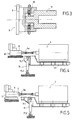
- la figure 3 est une coupe simplifiée d'un limiteur de couple ;
- la figure 4 est un schéma de la ligne d'arbre d'entraínement ;
- la figure 5 est un schéma de la ligne d'arbre de déchiquetage ;
- la figure 6 est une coupe longitudinale d'un système d'amortissement selon l'invention ;
- la figure 7 est un synoptique des moyens de commande et de contrôle de l'installation, et ;
- la figure 8 est une courbe définissant le couple exercé sur les arbres en fonction du temps.
- C1 est le couple maximal préréglé, de l'ordre de 700 000 Nm.
- C2 est le couple maximal admissible au-delà duquel il y a destruction de l'installation (zone D). C2 est de l'ordre de 820 000 Nm.
- Pour un couple compris entre C1 et C2, on se trouve encore dans une zone dite "de sécurité" de l'installation (zone S).
- En deçà de C1, on se trouve dans une zone de fonctionnement normal.
Claims (11)
- Installation de pré-broyage d'objets comprenant au moins un premier arbre d'entraínement (14) des objets et un deuxième arbre de déchiquetage (12) des objets entraínés, lesdits arbres étant chacun muni de crocs de déchiquetage (16) et étant chacun entraíné en rotation par au moins un moteur (7, 8), un réducteur (3, 4) de la vitesse de chaque moteur (7, 8) étant disposé entre chaque moteur et l'arbre associé (12, 14), l'installation comprenant en outre des moyens de commande desdits moteurs associés à des capteurs de paramètres de fonctionnement de l'installation, et un moyen (100) d'acquisition et de traitement des données, caractérisée en ce qu'elle comprend en outre un cardan (3a, 4a) disposé entre l'arbre de sortie de chaque moteur (7, 8) et l'arbre d'entrée de chaque réducteur (3, 4) et en ce que chaque réducteur est monté en appui sur un moyen d'amortissement (15, 17) ce qui permet d'absorber l'énergie créée par des chocs et/ou des couples supérieurs à un seuil donné au niveau des crocs (16).
- Installation selon la revendication 1, caractérisé en ce que le moyen d'amortissement (15) comprend un élément d'amortissement tel qu'un empilement de rondelles Belleville ou un vérin hydraulique.
- Installation de pré-broyage selon l'une quelconque des revendications précédentes, caractérisée en ce qu'elle comprend en outre un capteur de sécurité (15.2, 17.2) disposé sur chaque moyen d'amortissement (15, 17) et relié au moyen (100) qui réagit en arrêtant au moins les moteurs d'entraínement (7, 8) lorsque lesdits capteurs (15.2, 17.2) sont actionnés.
- Installation selon l'une quelconque des revendications précédentes, caractérisée en ce que les capteurs comprennent au moins un capteur d'efforts (15.1) placé sur le moyen d'amortissement (15) et relié au moyen (100) d'acquisition et de traitement de données.
- Installation de pré-broyage selon l'une quelconque des revendications précédentes, caractérisée en ce qu'elle comprend en outre des moyens de désolidarisation (5) entre l'un au moins des arbres (12, 14) et le moteur d'entraínement associé (7, 8).
- Installation selon l'une quelconque des revendications 2 ou 3, caractérisée en ce que les moyens de désolidarisation comprennent au moins un limiteur de couple (5).
- Installation selon la revendication 6, caractérisée en ce que le limiteur de couple est associé au deuxième arbre (12).
- Installation selon l'une quelconque des revendications 6 ou 7, caractérisée en ce qu'elle comprend un limiteur de couple (5) associé à chacun des arbres (12, 14).
- Installation selon l'une quelconque des revendications précédentes, caractérisée en ce que les capteurs comprennent au moins un capteur (71, 81) de vitesse associé à au moins un des moteurs d'entraínement (8) et/ou de déchiquetage (7), et relié au moyen (100) d'acquisition et de traitement des données.
- Installation selon l'une quelconque des revendications précédentes, caractérisée en ce que les capteurs comprennent au moins un détecteur placé sur les moyens de désolidarisation (5) afin d'en contrôler le déclenchement, le(s) détecteur(s) étant relié(s) au moyen (100) d'acquisition et de traitement des données.
- Installation selon l'une quelconque des revendications précédentes, caractérisée en ce que le(ou lesdits) moteur(s) est un moteur électrique, soit à courant continu, soit à courant alternatif.
Applications Claiming Priority (2)
| Application Number | Priority Date | Filing Date | Title |
|---|---|---|---|
| FR0115699 | 2001-12-05 | ||
| FR0115699A FR2832939B1 (fr) | 2001-12-05 | 2001-12-05 | Installation amelioree de pre-broyage d'objets |
Publications (2)
| Publication Number | Publication Date |
|---|---|
| EP1319438A1 true EP1319438A1 (fr) | 2003-06-18 |
| EP1319438B1 EP1319438B1 (fr) | 2005-10-12 |
Family
ID=8870120
Family Applications (1)
| Application Number | Title | Priority Date | Filing Date |
|---|---|---|---|
| EP02292972A Expired - Lifetime EP1319438B1 (fr) | 2001-12-05 | 2002-12-03 | Installation améliorée de pré-broyage d'objets |
Country Status (7)
| Country | Link |
|---|---|
| US (1) | US6836089B2 (fr) |
| EP (1) | EP1319438B1 (fr) |
| AT (1) | ATE306327T1 (fr) |
| CA (1) | CA2413605C (fr) |
| DE (1) | DE60206588T2 (fr) |
| ES (1) | ES2250604T3 (fr) |
| FR (1) | FR2832939B1 (fr) |
Families Citing this family (7)
| Publication number | Priority date | Publication date | Assignee | Title |
|---|---|---|---|---|
| JP2004322076A (ja) * | 2003-04-09 | 2004-11-18 | Komatsu Ltd | せん断破砕機の破砕制御装置 |
| JP2004322075A (ja) * | 2003-04-09 | 2004-11-18 | Komatsu Ltd | 破砕機の負荷表示装置 |
| US20100210386A1 (en) * | 2009-02-13 | 2010-08-19 | Long Jr Thomas F | Torque limiter arrangement for a horizontal grinder |
| US8162246B2 (en) * | 2009-03-03 | 2012-04-24 | Randall Long | Multiple safety element torque limiter |
| AU2011253613B2 (en) * | 2010-11-30 | 2014-08-14 | Joy Global Surface Mining Inc | Moveable shaft assembly |
| JP5967833B2 (ja) * | 2013-12-12 | 2016-08-10 | 株式会社キンキ | 2軸式破袋装置 |
| CN109174369A (zh) * | 2018-09-27 | 2019-01-11 | 湖北力帝机床股份有限公司 | 一种用于预碎机的浮动刀盘结构及控制方法 |
Citations (4)
| Publication number | Priority date | Publication date | Assignee | Title |
|---|---|---|---|---|
| FR2292520A1 (fr) * | 1974-11-26 | 1976-06-25 | Gaemmerler Hagen | Broyeur vibrant, notamment pour pierrailles |
| DD134921A1 (de) * | 1978-03-13 | 1979-04-04 | Bernd Pester | Antrieb fuer walzenmuehlen |
| US4346850A (en) * | 1980-08-18 | 1982-08-31 | Mitts & Merrill Inc. | Shredding machine incorporating a torque cushioning assembly |
| WO1998007519A1 (fr) * | 1996-08-21 | 1998-02-26 | Compagnie Française Des Ferrailles | Installation de pre-broyage |
Family Cites Families (6)
| Publication number | Priority date | Publication date | Assignee | Title |
|---|---|---|---|---|
| DE134921C (fr) | ||||
| US3796151A (en) * | 1972-06-19 | 1974-03-12 | J Williams | Auto flattening press |
| US4188876A (en) * | 1976-01-14 | 1980-02-19 | Graves Donald J | Junk metal compressor |
| US4625636A (en) * | 1982-02-10 | 1986-12-02 | Car-Go, Corp. | Vehicle compactor |
| JP2777773B2 (ja) * | 1993-10-25 | 1998-07-23 | 株式会社小松製作所 | 自走式破砕機械 |
| JP3449643B2 (ja) * | 1994-07-20 | 2003-09-22 | 株式会社小松製作所 | 自走式破砕機械の破砕機制御装置 |
-
2001
- 2001-12-05 FR FR0115699A patent/FR2832939B1/fr not_active Expired - Fee Related
-
2002
- 2002-12-02 US US10/307,672 patent/US6836089B2/en not_active Expired - Fee Related
- 2002-12-03 ES ES02292972T patent/ES2250604T3/es not_active Expired - Lifetime
- 2002-12-03 AT AT02292972T patent/ATE306327T1/de active
- 2002-12-03 DE DE60206588T patent/DE60206588T2/de not_active Expired - Lifetime
- 2002-12-03 EP EP02292972A patent/EP1319438B1/fr not_active Expired - Lifetime
- 2002-12-04 CA CA2413605A patent/CA2413605C/fr not_active Expired - Fee Related
Patent Citations (4)
| Publication number | Priority date | Publication date | Assignee | Title |
|---|---|---|---|---|
| FR2292520A1 (fr) * | 1974-11-26 | 1976-06-25 | Gaemmerler Hagen | Broyeur vibrant, notamment pour pierrailles |
| DD134921A1 (de) * | 1978-03-13 | 1979-04-04 | Bernd Pester | Antrieb fuer walzenmuehlen |
| US4346850A (en) * | 1980-08-18 | 1982-08-31 | Mitts & Merrill Inc. | Shredding machine incorporating a torque cushioning assembly |
| WO1998007519A1 (fr) * | 1996-08-21 | 1998-02-26 | Compagnie Française Des Ferrailles | Installation de pre-broyage |
Also Published As
| Publication number | Publication date |
|---|---|
| DE60206588D1 (de) | 2006-02-23 |
| FR2832939B1 (fr) | 2004-02-27 |
| US20030102827A1 (en) | 2003-06-05 |
| DE60206588T2 (de) | 2006-07-13 |
| EP1319438B1 (fr) | 2005-10-12 |
| ATE306327T1 (de) | 2005-10-15 |
| CA2413605A1 (fr) | 2003-06-05 |
| US6836089B2 (en) | 2004-12-28 |
| FR2832939A1 (fr) | 2003-06-06 |
| ES2250604T3 (es) | 2006-04-16 |
| CA2413605C (fr) | 2010-11-30 |
Similar Documents
| Publication | Publication Date | Title |
|---|---|---|
| EP2543593B1 (fr) | Système de motorisation électrique d'une roue | |
| CA2742194C (fr) | Dispositif electromecanique multifonctions pour atterrisseur | |
| EP0790385A1 (fr) | Dispositif de manoeuvre pour volet roulant | |
| EP2512855A1 (fr) | Moyeu motorise comprenant des moyens de couplage et de decouplage | |
| EP2588337A1 (fr) | Moyeu motorise comprenant une machine electrique de traction | |
| FR3003235A1 (fr) | Dispositif multifonctions pour atterriseurs. | |
| EP1319438B1 (fr) | Installation améliorée de pré-broyage d'objets | |
| CA3065657C (fr) | Procede de protection contre les chocs pouvant affecter un atterrisseur d'aeronef | |
| EP1488070B1 (fr) | Dispositif de securite et mecanisme de manoeuvre d'une installation de fermeture ou de protection solaire incorporant un tel dispositif | |
| EP3006333A1 (fr) | Atterrisseur d'aéronef | |
| FR2907637A1 (fr) | "dispositif debroussailleur-broyeur de vegetaux" | |
| FR2981886A1 (fr) | Transmission pour vehicule hybride a deux trains d'engrenages epicycloidaux a derivation de puissance et a recuperation de l'energie cinetique par volant d'inertie | |
| FR2986749A1 (fr) | Systeme d'entrainement et de direction d'une roue d'un vehicule | |
| EP3140238B1 (fr) | Treuil modulaire embarque | |
| WO2023194668A1 (fr) | Dispositif de protection du chargeur de batteries pour véhicules électriques et hybrides | |
| FR2673236A1 (fr) | Dispositif de securite pour portes a rideau relevable. | |
| EP0958059B1 (fr) | Installation de pre-broyage | |
| EP1783394B1 (fr) | Dispositif de sécurité de transmission mécanique par engrenage irréversible a l'arrêt | |
| EP4279308B1 (fr) | Sous-ensemble hybride d'entraînement d'un véhicule | |
| EP1719872B1 (fr) | Porte à arbre d'enroulement entraîné électriquement et procédé de contrôle de fonctionnement d'une telle porte | |
| EP2603323A1 (fr) | Broyeur ou concasseur a marteaux ou analogue muni d'un dispositif d'extraction du rotor | |
| EP2769082B1 (fr) | Démarreur pour moteur à combustion interne | |
| FR2669075A1 (fr) | Dispositif d'actionnement pour barriere automatique. | |
| FR2824057A1 (fr) | Suiveur d'entrainement de securite irreversible | |
| FR2881464A1 (fr) | Porte rapide avec dispositif de freinage |
Legal Events
| Date | Code | Title | Description |
|---|---|---|---|
| PUAI | Public reference made under article 153(3) epc to a published international application that has entered the european phase |
Free format text: ORIGINAL CODE: 0009012 |
|
| AK | Designated contracting states |
Designated state(s): AT BE BG CH CY CZ DE DK EE ES FI FR GB GR IE IT LI LU MC NL PT SE SI SK TR |
|
| AX | Request for extension of the european patent |
Extension state: AL LT LV MK RO |
|
| 17P | Request for examination filed |
Effective date: 20031202 |
|
| AKX | Designation fees paid |
Designated state(s): AT BE BG CH CY CZ DE DK EE ES FI FR GB GR IE IT LI LU MC NL PT SE SI SK TR |
|
| GRAP | Despatch of communication of intention to grant a patent |
Free format text: ORIGINAL CODE: EPIDOSNIGR1 |
|
| GRAS | Grant fee paid |
Free format text: ORIGINAL CODE: EPIDOSNIGR3 |
|
| GRAA | (expected) grant |
Free format text: ORIGINAL CODE: 0009210 |
|
| AK | Designated contracting states |
Kind code of ref document: B1 Designated state(s): AT BE BG CH CY CZ DE DK EE ES FI FR GB GR IE IT LI LU MC NL PT SE SI SK TR |
|
| PG25 | Lapsed in a contracting state [announced via postgrant information from national office to epo] |
Ref country code: TR Free format text: LAPSE BECAUSE OF FAILURE TO SUBMIT A TRANSLATION OF THE DESCRIPTION OR TO PAY THE FEE WITHIN THE PRESCRIBED TIME-LIMIT Effective date: 20051012 Ref country code: IE Free format text: LAPSE BECAUSE OF FAILURE TO SUBMIT A TRANSLATION OF THE DESCRIPTION OR TO PAY THE FEE WITHIN THE PRESCRIBED TIME-LIMIT Effective date: 20051012 Ref country code: NL Free format text: LAPSE BECAUSE OF FAILURE TO SUBMIT A TRANSLATION OF THE DESCRIPTION OR TO PAY THE FEE WITHIN THE PRESCRIBED TIME-LIMIT Effective date: 20051012 Ref country code: EE Free format text: LAPSE BECAUSE OF FAILURE TO SUBMIT A TRANSLATION OF THE DESCRIPTION OR TO PAY THE FEE WITHIN THE PRESCRIBED TIME-LIMIT Effective date: 20051012 Ref country code: FI Free format text: LAPSE BECAUSE OF FAILURE TO SUBMIT A TRANSLATION OF THE DESCRIPTION OR TO PAY THE FEE WITHIN THE PRESCRIBED TIME-LIMIT Effective date: 20051012 Ref country code: SK Free format text: LAPSE BECAUSE OF FAILURE TO SUBMIT A TRANSLATION OF THE DESCRIPTION OR TO PAY THE FEE WITHIN THE PRESCRIBED TIME-LIMIT Effective date: 20051012 Ref country code: SI Free format text: LAPSE BECAUSE OF FAILURE TO SUBMIT A TRANSLATION OF THE DESCRIPTION OR TO PAY THE FEE WITHIN THE PRESCRIBED TIME-LIMIT Effective date: 20051012 Ref country code: CZ Free format text: LAPSE BECAUSE OF FAILURE TO SUBMIT A TRANSLATION OF THE DESCRIPTION OR TO PAY THE FEE WITHIN THE PRESCRIBED TIME-LIMIT Effective date: 20051012 |
|
| REG | Reference to a national code |
Ref country code: GB Ref legal event code: FG4D Free format text: NOT ENGLISH |
|
| REG | Reference to a national code |
Ref country code: CH Ref legal event code: EP |
|
| REG | Reference to a national code |
Ref country code: IE Ref legal event code: FG4D Free format text: LANGUAGE OF EP DOCUMENT: FRENCH |
|
| PG25 | Lapsed in a contracting state [announced via postgrant information from national office to epo] |
Ref country code: CY Free format text: LAPSE BECAUSE OF FAILURE TO SUBMIT A TRANSLATION OF THE DESCRIPTION OR TO PAY THE FEE WITHIN THE PRESCRIBED TIME-LIMIT Effective date: 20051203 |
|
| PG25 | Lapsed in a contracting state [announced via postgrant information from national office to epo] |
Ref country code: MC Free format text: LAPSE BECAUSE OF NON-PAYMENT OF DUE FEES Effective date: 20051231 |
|
| PG25 | Lapsed in a contracting state [announced via postgrant information from national office to epo] |
Ref country code: SE Free format text: LAPSE BECAUSE OF FAILURE TO SUBMIT A TRANSLATION OF THE DESCRIPTION OR TO PAY THE FEE WITHIN THE PRESCRIBED TIME-LIMIT Effective date: 20060112 Ref country code: GR Free format text: LAPSE BECAUSE OF FAILURE TO SUBMIT A TRANSLATION OF THE DESCRIPTION OR TO PAY THE FEE WITHIN THE PRESCRIBED TIME-LIMIT Effective date: 20060112 Ref country code: BG Free format text: LAPSE BECAUSE OF FAILURE TO SUBMIT A TRANSLATION OF THE DESCRIPTION OR TO PAY THE FEE WITHIN THE PRESCRIBED TIME-LIMIT Effective date: 20060112 Ref country code: DK Free format text: LAPSE BECAUSE OF FAILURE TO SUBMIT A TRANSLATION OF THE DESCRIPTION OR TO PAY THE FEE WITHIN THE PRESCRIBED TIME-LIMIT Effective date: 20060112 |
|
| REG | Reference to a national code |
Ref country code: CH Ref legal event code: NV Representative=s name: MICHELI & CIE INGENIEURS-CONSEILS |
|
| GBT | Gb: translation of ep patent filed (gb section 77(6)(a)/1977) |
Effective date: 20060110 |
|
| REF | Corresponds to: |
Ref document number: 60206588 Country of ref document: DE Date of ref document: 20060223 Kind code of ref document: P |
|
| NLV1 | Nl: lapsed or annulled due to failure to fulfill the requirements of art. 29p and 29m of the patents act | ||
| REG | Reference to a national code |
Ref country code: ES Ref legal event code: FG2A Ref document number: 2250604 Country of ref document: ES Kind code of ref document: T3 |
|
| REG | Reference to a national code |
Ref country code: IE Ref legal event code: FD4D |
|
| PLBE | No opposition filed within time limit |
Free format text: ORIGINAL CODE: 0009261 |
|
| STAA | Information on the status of an ep patent application or granted ep patent |
Free format text: STATUS: NO OPPOSITION FILED WITHIN TIME LIMIT |
|
| 26N | No opposition filed |
Effective date: 20060713 |
|
| PGFP | Annual fee paid to national office [announced via postgrant information from national office to epo] |
Ref country code: LU Payment date: 20131120 Year of fee payment: 12 |
|
| PGFP | Annual fee paid to national office [announced via postgrant information from national office to epo] |
Ref country code: GB Payment date: 20131217 Year of fee payment: 12 Ref country code: AT Payment date: 20131119 Year of fee payment: 12 Ref country code: DE Payment date: 20131210 Year of fee payment: 12 Ref country code: PT Payment date: 20130603 Year of fee payment: 12 Ref country code: CH Payment date: 20131212 Year of fee payment: 12 |
|
| PGFP | Annual fee paid to national office [announced via postgrant information from national office to epo] |
Ref country code: IT Payment date: 20131211 Year of fee payment: 12 Ref country code: ES Payment date: 20131219 Year of fee payment: 12 |
|
| PGFP | Annual fee paid to national office [announced via postgrant information from national office to epo] |
Ref country code: BE Payment date: 20131223 Year of fee payment: 12 |
|
| PGFP | Annual fee paid to national office [announced via postgrant information from national office to epo] |
Ref country code: FR Payment date: 20131223 Year of fee payment: 12 |
|
| REG | Reference to a national code |
Ref country code: PT Ref legal event code: MM4A Free format text: LAPSE DUE TO NON-PAYMENT OF FEES Effective date: 20150603 |
|
| PG25 | Lapsed in a contracting state [announced via postgrant information from national office to epo] |
Ref country code: BE Free format text: LAPSE BECAUSE OF NON-PAYMENT OF DUE FEES Effective date: 20141231 |
|
| REG | Reference to a national code |
Ref country code: DE Ref legal event code: R119 Ref document number: 60206588 Country of ref document: DE |
|
| PG25 | Lapsed in a contracting state [announced via postgrant information from national office to epo] |
Ref country code: PT Free format text: LAPSE BECAUSE OF NON-PAYMENT OF DUE FEES Effective date: 20150603 Ref country code: LU Free format text: LAPSE BECAUSE OF NON-PAYMENT OF DUE FEES Effective date: 20141203 |
|
| REG | Reference to a national code |
Ref country code: CH Ref legal event code: PL |
|
| REG | Reference to a national code |
Ref country code: AT Ref legal event code: MM01 Ref document number: 306327 Country of ref document: AT Kind code of ref document: T Effective date: 20141203 |
|
| GBPC | Gb: european patent ceased through non-payment of renewal fee |
Effective date: 20141203 |
|
| REG | Reference to a national code |
Ref country code: FR Ref legal event code: ST Effective date: 20150831 |
|
| PG25 | Lapsed in a contracting state [announced via postgrant information from national office to epo] |
Ref country code: DE Free format text: LAPSE BECAUSE OF NON-PAYMENT OF DUE FEES Effective date: 20150701 Ref country code: LI Free format text: LAPSE BECAUSE OF NON-PAYMENT OF DUE FEES Effective date: 20141231 Ref country code: CH Free format text: LAPSE BECAUSE OF NON-PAYMENT OF DUE FEES Effective date: 20141231 Ref country code: GB Free format text: LAPSE BECAUSE OF NON-PAYMENT OF DUE FEES Effective date: 20141203 |
|
| PG25 | Lapsed in a contracting state [announced via postgrant information from national office to epo] |
Ref country code: AT Free format text: LAPSE BECAUSE OF NON-PAYMENT OF DUE FEES Effective date: 20141203 Ref country code: FR Free format text: LAPSE BECAUSE OF NON-PAYMENT OF DUE FEES Effective date: 20141231 |
|
| PG25 | Lapsed in a contracting state [announced via postgrant information from national office to epo] |
Ref country code: IT Free format text: LAPSE BECAUSE OF NON-PAYMENT OF DUE FEES Effective date: 20141203 |
|
| REG | Reference to a national code |
Ref country code: ES Ref legal event code: FD2A Effective date: 20160503 |
|
| PG25 | Lapsed in a contracting state [announced via postgrant information from national office to epo] |
Ref country code: ES Free format text: LAPSE BECAUSE OF NON-PAYMENT OF DUE FEES Effective date: 20141204 |