EP1320003A2 - Verfahren und Gerät zur Anordnung einer Einheit - Google Patents
Verfahren und Gerät zur Anordnung einer Einheit Download PDFInfo
- Publication number
- EP1320003A2 EP1320003A2 EP02027583A EP02027583A EP1320003A2 EP 1320003 A2 EP1320003 A2 EP 1320003A2 EP 02027583 A EP02027583 A EP 02027583A EP 02027583 A EP02027583 A EP 02027583A EP 1320003 A2 EP1320003 A2 EP 1320003A2
- Authority
- EP
- European Patent Office
- Prior art keywords
- unit
- shape
- design
- function blocks
- designing
- Prior art date
- Legal status (The legal status is an assumption and is not a legal conclusion. Google has not performed a legal analysis and makes no representation as to the accuracy of the status listed.)
- Granted
Links
Images



Classifications
-
- G—PHYSICS
- G05—CONTROLLING; REGULATING
- G05B—CONTROL OR REGULATING SYSTEMS IN GENERAL; FUNCTIONAL ELEMENTS OF SUCH SYSTEMS; MONITORING OR TESTING ARRANGEMENTS FOR SUCH SYSTEMS OR ELEMENTS
- G05B19/00—Program-control systems
- G05B19/02—Program-control systems electric
- G05B19/418—Total factory control, i.e. centrally controlling a plurality of machines, e.g. direct or distributed numerical control [DNC], flexible manufacturing systems [FMS], integrated manufacturing systems [IMS] or computer integrated manufacturing [CIM]
- G05B19/41885—Total factory control, i.e. centrally controlling a plurality of machines, e.g. direct or distributed numerical control [DNC], flexible manufacturing systems [FMS], integrated manufacturing systems [IMS] or computer integrated manufacturing [CIM] characterised by modeling, simulation of the manufacturing system
-
- Y—GENERAL TAGGING OF NEW TECHNOLOGICAL DEVELOPMENTS; GENERAL TAGGING OF CROSS-SECTIONAL TECHNOLOGIES SPANNING OVER SEVERAL SECTIONS OF THE IPC; TECHNICAL SUBJECTS COVERED BY FORMER USPC CROSS-REFERENCE ART COLLECTIONS [XRACs] AND DIGESTS
- Y02—TECHNOLOGIES OR APPLICATIONS FOR MITIGATION OR ADAPTATION AGAINST CLIMATE CHANGE
- Y02P—CLIMATE CHANGE MITIGATION TECHNOLOGIES IN THE PRODUCTION OR PROCESSING OF GOODS
- Y02P90/00—Enabling technologies with a potential contribution to greenhouse gas [GHG] emissions mitigation
- Y02P90/02—Total factory control, e.g. smart factories, flexible manufacturing systems [FMS] or integrated manufacturing systems [IMS]
Definitions
- the present invention relates to unit designing apparatus and method for designing a unit including a plurality of function blocks.
- a unit including a plurality of function blocks such as an engine of a vehicle
- the design team After determining a target for an engine design, the design team first designs the basic shape of the overall engine. Considerations related to the production engineering team are most commonly not taken into account until after the basic shape has been substantially decided and the prospective design of the overall engine design is already in view.
- Fig. 9 is a flowchart showing a common procedure for designing an engine, shown as a conventional example procedure for designing a unit including a plurality of function blocks.
- the basic specifications are determined after the engine design target is given.
- the design target may be defined as an engine type such as a V-6 gasoline fueled engine, a displacement such as 3.5 liters, a predetermined value of target output, and the like.
- the basic dimensions of the individual engine components is determined based on such design criteria.
- the basic cross-section designing step S3 the basic cross-section of the engine is designed in accordance with the basic specifications, and a drawing is created.
- the basic skeleton designing step S5 a skeleton view including positions for the respective function blocks is designed and illustrated in accordance with the basic cross-sectional view. Further design is subsequently accomplished by incorporating details of each of the function blocks into this skeleton view.
- the steps of S3 and S5 may be executed in manners other than those described above.
- the basic shape designing step S7 is for incorporating the details of the function blocks into the skeleton view.
- various design aspects are performed while taking into account factors such as the outer shape and positional arrangement of each function block and the relationships between the function blocks, such that the overall engine achieves the design targets.
- requests concerning production technique requirements imposed by the design are conveyed from the design team to the production engineering team.
- no systematic discussions are held between the design team and the production engineering team. Accordingly, the steps up to S7 to design a new discrete engine for each design target, determine the basic shape, and bring the prospective design of the overall engine in view are executed almost entirely by the design team.
- the production technique consulting step S9 is performed to intensively consult on matters concerning production technique requirements in accordance with the basic shape design.
- the shapes of raw materials prior to machining are designed for the entire engine.
- aspects of the basic shape design that should be altered to accommodate the circumstances of production techniques are modified in the raw material shape design, where possible.
- metal, wooden, or other molds for the engine frame and the function blocks are designed.
- the product shapes after machining are designed for the entire engine based on the raw material shape design.
- the product shape design accommodations for matters concerning the production techniques are made in the product shape design, where possible. Machining steps, processes, tools and jigs, facilities, and the like are then determined based on the product shape design.
- the engine is fabricated using the molds formed in accordance with the raw material shape design and by performing the machining processes in accordance with the product shape design.
- step S17 tests are performed to determine whether the fabricated engine achieves the design targets. Further, the engine is evaluated for its mountability and assembly onto a vehicle, the strength of each of the parts, and the like. When problems are found as a result of the evaluation, the problems are dealt with by returning to the proper step in the engine designing procedure.
- the design team designs a new discrete engine for each design target, determines the basic shape, and brings the prospective design of the overall engine in view before consulting with the production engineering team.
- An object of the present invention is to reflect, in design of a new unit including a plurality of function blocks, the accumulated results of past design examples for which consultations concerning production techniques were performed, thereby eliminating repetition of designs and reducing time required for development. Further objects are to allow consultation regarding aspects concerning production techniques before determining the basic shape of the unit, to allow sufficient evaluations of mountability, assembly, strength, and the like to be conducted at an earlier stage, and to allow an engine design team and a production engineering team to simultaneously participate in design. Another object of the present invention is to accumulate the results of the new design as an additional design example, so as to further enhance the level of unit design standardization.
- the present invention provides a unit designing apparatus for designing a unit including a plurality of function blocks, comprising a function block memory for storing a design example including an outer shape of each of the function blocks in association with a specification including a basic dimension of the unit, a search engine for searching, with respect to each of the plurality of function blocks, a design example to be applied in correlation to a specification of the unit, and a raw material shape designing device for laying out, in a basic structural view of the unit, an outer shape for each of the function blocks obtained as a result of the search to thereby design a raw material shape for the unit.
- the unit designing apparatus further comprises a production machining information memory for storing production machining information including a machining shape applied to a design example for each of the function blocks, a production machining information search engine for searching production machining information including a machining shape for application to each of the function blocks in its raw material shape, and a product shape designing device for application to the raw material shape for the unit a machining shape for each of the function blocks obtained as a result of the search to thereby design a product shape for the unit.
- a production machining information memory for storing production machining information including a machining shape applied to a design example for each of the function blocks
- a production machining information search engine for searching production machining information including a machining shape for application to each of the function blocks in its raw material shape
- a product shape designing device for application to the raw material shape for the unit a machining shape for each of the function blocks obtained as a result of the search to thereby design a product shape for the unit.
- the present invention further provides a unit designing method for designing a unit including a plurality of function blocks, comprising a searching step for searching, in a function block database storing a design example including an outer shape of each of the function blocks in association with a specification including a basic dimension of the unit, a design example for application to each of the plurality of function blocks in correlation to a specification of the unit.
- the method additionally comprises a raw material shape designing step for laying out, in a basic structural view of the unit, an outer shape for each of the function blocks obtained as a result of the search to thereby design a raw material shape for the unit.
- the unit designing method may further comprise a production machining information searching step for searching, in a production machining information database storing production machining information including a machining shape applied to a design example for each of the function blocks, production machining information including a machining shape for application to each of the function blocks in its raw material shape .
- the method additionally comprises a product shape designing step for applying to the raw material shape for the unit a machining shape for each of the function blocks obtained as a result of the search to thereby design a product shape for the unit.
- a design example including an outer shape of each of the function blocks may be stored in association with a specification including a basic dimension of the unit.
- a design example that can be applied is searched for each of the plurality of function blocks using a specification of the unit as the key.
- An outer shape for each of the function blocks obtained as a result of the search is then laid out in a basic structural view of the unit to thereby design a raw material shape for the unit.
- the level of unit design standardization can be further enhanced.
- production machining information including a machining shape applied to each function block is stored.
- production machining information including a machining shape for application to each of the function blocks in its raw material shape is searched.
- a machining shape for each of the function blocks obtained as a result of the search is then applied to the raw material shape for the unit to thereby design a product shape for the unit.
- the machining shape referred to herein may include a shape into which a material is processed by machining or the like.
- the present invention further provides a unit designing apparatus for designing a unit including a plurality of function blocks, comprising a function block memory for storing a design example including an outer shape of each of the function blocks in association with a specification including a basic dimension of the unit, a search engine for searching, with respect to each of the plurality of function blocks, a design example to be applied in correlation to a specification of the unit, a function block registering device for newly registering in the function block memory a function block newly designed by referring to the searched design example, and a raw material shape designing device for laying out, in a basic structural view of the unit, an outer shape for each of the function blocks obtained as a result of a search in the memory including the newly registered function block, to thereby design a raw material shape for the unit.
- a unit designing apparatus for designing a unit including a plurality of function blocks, comprising a function block memory for storing a design example including an outer shape of each of the function blocks in association with a specification including a basic dimension of the unit,
- the unit designing apparatus may further comprise a production machining information memory for storing production machining information including a machining shape applied to a design example for each of the function blocks, a production machining information search engine for searching production machining information including a machining shape for application to each of the function blocks in its raw material shape, a production machining information registering device for registering, in the production machining information memory, production machining information created by referring to the searched production machining information for application to the newly designed function block, and a product shape designing device for applying to the raw material shape for the unit a machining shape for each of the function blocks obtained as a result of a search in the memory including production machining information for application to the newly designed function block, to thereby design a product shape for the unit.
- a production machining information memory for storing production machining information including a machining shape applied to a design example for each of the function blocks
- a production machining information search engine for searching production machining information including a machining shape for application to each of the function blocks in its raw material shape
- the present invention further provides a unit designing method for designing a unit including a plurality of function blocks, comprising a searching step for searching, in a function block database storing a design example including an outer shape of each of the function blocks in association with a specification including a basic dimension of the unit, a design example for application to each of the plurality of function blocks in correlation to a specification of the unit.
- the method additionally comprises a function block registering step for newly registering in the function block database a function block newly designed by referring to the searched design example, and a raw material shape designing step for laying out, in a basic structural view of the unit, an outer shape for each of the function blocks obtained as a result of a search in the database including the newly registered function block, to thereby design a raw material shape for the unit.
- the unit designing method according to the present invention may further comprise a production machining information searching step for searching, in a production machining information database storing production machining information including a machining shape applied to a design example for each of the function blocks, production machining information including a machining shape for application to each of the function blocks in its raw material shape.
- the method additionally comprises a production machining information registering step for registering, in the production machining information database, production machining information created by referring to the searched production machining information for application to the newly designed function block, and a product shape designing step for applying to the raw material shape for the unit a machining shape for each of the function blocks obtained as a result of a search in the database including the production machining information for application to the newly designed function block, to thereby design a product shape for the unit.
- a new function block incorporating such new technologies can be designed by referring to or consulting design examples already stored in the function block database, and the designed function block can be newly registered in the function block database.
- new production machining information for application to the newly designed function block can be created by referring to or consulting the production machining data already stored in the production machining information database, and the created machining information can be newly registered in the production machining information database.
- designing of a unit raw material shape incorporating new technologies can be accomplished, and creation of a unit product shape incorporating new technologies can also be achieved.
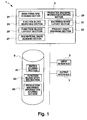
- FIG. 1 is a block diagram showing the unit designing apparatus 1 which is a typical computer.
- the unit designing apparatus 1 comprises a CPU 3, an input interface 5, an output interface 7, and an external memory device 9, all of which are connected via a bus.
- the unit designing apparatus 1 may connect to an externally provided database through a network connection via the input interface 5 and the output interface 7.
- the CPU 3 includes a basic structure designing section 21 for designing a basic structure in accordance with a given design target, and a function block searching section 23 for searching a design example of a function block for application to the engine concerned.
- the function block layout section 25 lays out a searched outer shape of a function block in a basic structural view.
- the raw material shape designing section 27 designs a raw material shape.
- the CPU 3 further includes a production machining information searching section 29 for searching production machining information for application to each function block.
- the machining shape layout section 31 lays out a machining shape of each function block obtained from the searched production machining information in a raw material shape design drawing.
- a product shape is designed in the product shape designing section 33.
- the external memory device 9 includes a matrix storing section 41 for storing various correlations between engines and the function blocks in a matrix, a function block storing section 43 for storing design examples for the respective function blocks, and a production machining information storing section 45 for storing production machining information for application to the function blocks.
- Fig. 2 is a diagram for explaining a data structure for matrix data 51, function block data 53, and production machining information data 55, which are stored in the matrix storing section 41, the function block storing section 43, and the production machining information storing section 45, respectively.
- an engine type such as V-6 gasoline engine, a basic dimension of the engine such as a displacement of 3.5 liters, a target output, and the like are given to define the criteria of the design target.
- the data are therefore stored in a data structure which allows data necessary for engine design to be searched based on engine types, basic dimensions represented by displacement, and the like.
- the matrix data 51 is organized in a data structure in which data are grouped according to engine type.
- Data for each engine type includes basic dimension data represented by displacement and function block design example data. For example, when "V-6 gasoline engine” is input as the selected engine type, past design examples accumulated for that engine type can be searched in a matrix comprising displacement data and data for each of the function blocks. When the displacement of 3.5 liters is selected in this matrix, the design examples for the respective function blocks that may be used in an engine having that particular displacement can be searched. In the example of Fig.
- the data search provides the information that a V-6 gasoline engine having the displacement of 3.5 liters can be constituted by employing a combination including bore type C as the bore, liner type C as the liner, and other function blocks ⁇ -C, ⁇ -D, ⁇ -C, and ⁇ -F.
- the function block data 53 is organized in a data structure in which data are grouped by each function block, and the data grouped according to function block are in turn grouped by design example.
- Data for each design example includes design data including the outer shape of the function block for that design example. For example, when "bore" is input as the selected function block, a list of accumulated past design examples for bore is indicated. When selecting the design example of bore C, data including the outer shape, detailed drawing, dimension specification, and the like concerning bore C can be searched.
- the production machining information data 55 is organized in a data structure in which data are grouped according to design example of each function block.
- Data for each design example includes production machining data such as the machining or other machining shape, standard processing procedure, standard processing conditions, standard tools, standard jigs, and standard facilities. For example, when "bore C" is input as the selected function block design example, production machining data with respect to bore C can be retrieved.
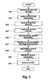
- the specification including the basic dimensions of the engine, such as displacement are set.
- the displacement may be specified as a 3.5 liter V-6 gasoline engine.
- the basic structure designing section of the CPU 3 creates, based on the new engine design concept, the basic skeleton view and basic structural view showing the arrangement relationship among the function blocks.
- Fig. 4 shows an example of such a basic structural view of a V-6 gasoline engine.
- the function block searching section 23 searches a design example including an outer shape for application to each function block in correlation with the engine specification.
- the search can be conducted using a specification of the engine as the key.
- V-6 gasoline engine By inputting "V-6 gasoline engine", a matrix associated with that engine type can be read out.
- a combination of design examples of the respective function blocks that constitute the engine to be designed can be read out.
- Fig. 2 a combination including bore C, liner C, ⁇ -C, ⁇ -D, ⁇ -C, and ⁇ -F is obtained.
- information including the outer shape is read out concerning each of bore C, liner C, and so on.
- Fig. 5 shows schematic views of the thus searched items including bore C and liner C, and the like.
- the function block layout section 25 lays out, in the basic structural view obtained in S23, the outer shapes of the respective function blocks searched in S25.
- the raw material shape designing section 27 designs the engine raw material shape prior to machining, based on the basic structural view including the laid-out outer shapes of the respective function blocks obtained in S27.
- the obtained data are insufficient, such as in a case where S25 did not provide data for all of the function blocks constituting the new engine, required components are designed in the present step. Further, components which cannot be incorporated into the data may be designed by simultaneous participation of the design team and the production engineering team.
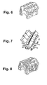
- Fig. 6 shows a schematic view of the engine raw material shape designed based on the basic structural view incorporating the laid-out outer shapes of the respective function blocks.
- a new function block incorporating new technologies can be designed by referring to or consulting, the design examples already stored in the function block storing section 43.
- a new function block is designed according to the following procedure, and the newly designed function block is subsequently registered in the function block storing section 43.
- a specification of the engine to be designed is first determined, and then a function block for incorporating a new technology is identified.
- a design example for application to the identified block is searched in the function block storing section 43.
- the procedure up to this point is identical to the basic structure designing step S23 and the function block searching step S25 described above.
- a determination is made as to whether the searched features of bore C fulfill the conditions for incorporating the new technology concerned.
- the searched features of bore C do not fulfill the conditions for incorporating the new technology
- the features of other registered bores such as bore A and bore B are searched and referred to in addition to those of bore C.
- the searched design examples are then consulted to design a new bore N.
- the outer shape, detailed diagram, dimension specification, and the like for the new bore N are defined by referring to the design examples and sufficiently studying whether the new shape can be manufactured using the existing production techniques and facilities. Simultaneous participation of the design team and the production engineering team is preferred during design of a new function block.
- a new design may be formed simply by editing the existing designs, or, alternatively, it may be determined that creation of a new outer shape differing from the existing designs is required.
- the new function block designed by incorporating a new technology while referring to existing design examples as described above is then registered in the function block storing section 43 in association with its engine specification. Subsequently, the designing procedure is continued by executing the function block searching step S25 and other subsequent steps, thereby enabling design of a unit raw material shape using the function block incorporating a new technology.
- the production machining information searching section 29 searches, in the production machining information storing section 45, production machining information including machining shapes with respect to each of the design examples of the respective function blocks. For example, inputting "bore C" triggers execution of a search for production machining data including the machining shape, standard processing procedure, standard processing conditions, standard tools, standard jigs, and standard facilities for bore C.
- Fig. 7 is a schematic view synthesizing the searched machining shapes for the respective function blocks.
- the machining shape layout section 31 lays out the machining shapes acquired through the above search in the raw material shape drawing obtained in S29.
- the machining or other processing shapes of the respective function blocks may be separately laid out, or, alternatively, laid out in the synthesized state shown in Fig. 7.
- the product shape designing section 33 designs the engine product shape after machining based on the raw material shape drawing incorporating the laid-out machining shapes of the function blocks formed in S33.
- the acquired data are insufficient, such as in a case where S31 did not provide data for all of the function blocks constituting the new engine, missing sections are designed in the present step. Further, sections which cannot be incorporated into the data may be designed by simultaneous participation of the design team and the production engineering team.
- Fig. 8 shows a schematic view of the engine product shape designed based on the raw material shape drawing incorporating the laid-out machining shapes of the function blocks.
- new function blocks are designed to continually incorporate new technologies, and the data such as the outer shapes of such newly designed function blocks are registered in the function block storing section 43.
- bore N is newly registered in the function block storing section 43.
- production machining information associated with the new function block is created by searching and referring to or consulting the existing production machining information stored in the production machining information storing section 45. It is apparent that this step of creating production machining information may immediately follow the step of designing the new function block. According to the above example, production machining data including the machining shape, processing steps, tools, jigs, facilities, and the like for bore N are created. Simultaneous participation of the design team and the production engineering team is preferred during creation of the production machining information for the new function block.
- the created data are registered in the production machining information storing section 45 in association with the new function block.
- it is determined that existing production machining information is sufficient for the new function block that existing production machining information is correlated to the new function block.
- the designing procedure is continued by executing the production machining information searching step S31 and other subsequent steps, thereby allowing designing of a unit product shape using a function block incorporating a new technology.
- the data storing step S37 is executed whenever a new engine design is completed to store the data for the new engine design in the matrix storing section 41, the function block storing section 43, and the production machining information storing section 45.
- the matrix storing section 41, the function block storing section 43, and the production machining information storing section 45 accumulate additional data each time a new design is created.
- the accumulated results of past design examples for which consultations concerning production techniques were performed can be reflected in the new design, thereby preventing repetitive design and thereby reducing time the required for development.
- consultation regarding aspects of production techniques can be accomplished before the basic shape of the unit is decided, at points such as before the raw material shape and the product shape are designed. This makes it possible to conduct sufficient evaluations of mountability, assembly, strength, and the like at an earlier stage. Furthermore, the design team and the production engineering team can simultaneously participate in design.
- results of the new design can be accumulated as an additional design example, thereby further enhancing the level of unit design standardization.
Landscapes
- Engineering & Computer Science (AREA)
- Manufacturing & Machinery (AREA)
- General Engineering & Computer Science (AREA)
- Quality & Reliability (AREA)
- Physics & Mathematics (AREA)
- General Physics & Mathematics (AREA)
- Automation & Control Theory (AREA)
- Management, Administration, Business Operations System, And Electronic Commerce (AREA)
- General Factory Administration (AREA)
Applications Claiming Priority (4)
| Application Number | Priority Date | Filing Date | Title |
|---|---|---|---|
| JP2001377166 | 2001-12-11 | ||
| JP2001377166 | 2001-12-11 | ||
| JP2002337619A JP4225038B2 (ja) | 2001-12-11 | 2002-11-21 | ユニット設計装置およびユニット設計方法 |
| JP2002337619 | 2002-11-21 |
Publications (3)
| Publication Number | Publication Date |
|---|---|
| EP1320003A2 true EP1320003A2 (de) | 2003-06-18 |
| EP1320003A3 EP1320003A3 (de) | 2005-04-06 |
| EP1320003B1 EP1320003B1 (de) | 2011-08-24 |
Family
ID=26624989
Family Applications (1)
| Application Number | Title | Priority Date | Filing Date |
|---|---|---|---|
| EP02027583A Expired - Lifetime EP1320003B1 (de) | 2001-12-11 | 2002-12-10 | Verfahren und Gerät zur Anordnung einer Einheit |
Country Status (5)
| Country | Link |
|---|---|
| US (1) | US6876900B2 (de) |
| EP (1) | EP1320003B1 (de) |
| JP (1) | JP4225038B2 (de) |
| CN (1) | CN1249614C (de) |
| PL (1) | PL357662A1 (de) |
Families Citing this family (27)
| Publication number | Priority date | Publication date | Assignee | Title |
|---|---|---|---|---|
| JP2003186927A (ja) * | 2001-12-17 | 2003-07-04 | Toyota Motor Corp | 型成形材生産プロセス設計装置および型成形材生産プロセス設計方法 |
| US7823077B2 (en) | 2003-03-24 | 2010-10-26 | Microsoft Corporation | System and method for user modification of metadata in a shell browser |
| US7240292B2 (en) * | 2003-04-17 | 2007-07-03 | Microsoft Corporation | Virtual address bar user interface control |
| US7712034B2 (en) | 2003-03-24 | 2010-05-04 | Microsoft Corporation | System and method for shell browser |
| US7769794B2 (en) | 2003-03-24 | 2010-08-03 | Microsoft Corporation | User interface for a file system shell |
| US7421438B2 (en) * | 2004-04-29 | 2008-09-02 | Microsoft Corporation | Metadata editing control |
| US7627552B2 (en) | 2003-03-27 | 2009-12-01 | Microsoft Corporation | System and method for filtering and organizing items based on common elements |
| US7890960B2 (en) | 2003-03-26 | 2011-02-15 | Microsoft Corporation | Extensible user context system for delivery of notifications |
| US7827561B2 (en) | 2003-03-26 | 2010-11-02 | Microsoft Corporation | System and method for public consumption of communication events between arbitrary processes |
| US7650575B2 (en) | 2003-03-27 | 2010-01-19 | Microsoft Corporation | Rich drag drop user interface |
| US7925682B2 (en) * | 2003-03-27 | 2011-04-12 | Microsoft Corporation | System and method utilizing virtual folders |
| US20050188174A1 (en) * | 2003-10-12 | 2005-08-25 | Microsoft Corporation | Extensible creation and editing of collections of objects |
| US8024335B2 (en) | 2004-05-03 | 2011-09-20 | Microsoft Corporation | System and method for dynamically generating a selectable search extension |
| US7181463B2 (en) | 2003-10-24 | 2007-02-20 | Microsoft Corporation | System and method for managing data using static lists |
| US7657846B2 (en) | 2004-04-23 | 2010-02-02 | Microsoft Corporation | System and method for displaying stack icons |
| US7694236B2 (en) * | 2004-04-23 | 2010-04-06 | Microsoft Corporation | Stack icons representing multiple objects |
| US7992103B2 (en) * | 2004-04-26 | 2011-08-02 | Microsoft Corporation | Scaling icons for representing files |
| US8707209B2 (en) * | 2004-04-29 | 2014-04-22 | Microsoft Corporation | Save preview representation of files being created |
| US8108430B2 (en) * | 2004-04-30 | 2012-01-31 | Microsoft Corporation | Carousel control for metadata navigation and assignment |
| CN100410952C (zh) * | 2004-08-23 | 2008-08-13 | 夏普株式会社 | 设计支援装置和设计支援方法 |
| US20060236244A1 (en) * | 2005-04-15 | 2006-10-19 | Microsoft Corporation | Command links |
| US7614016B2 (en) | 2005-04-21 | 2009-11-03 | Microsoft Corporation | Multiple roots in navigation pane |
| US8195646B2 (en) | 2005-04-22 | 2012-06-05 | Microsoft Corporation | Systems, methods, and user interfaces for storing, searching, navigating, and retrieving electronic information |
| US7665028B2 (en) | 2005-07-13 | 2010-02-16 | Microsoft Corporation | Rich drag drop user interface |
| KR20120085420A (ko) * | 2011-01-24 | 2012-08-01 | 두산인프라코어 주식회사 | 컴퓨터 수치 제어 공작기계에서 대화형 프로그램을 이용한 가공 형상 입력 장치 및 방법 |
| US9582589B2 (en) * | 2013-03-15 | 2017-02-28 | Facebook, Inc. | Social filtering of user interface |
| CN103942377B (zh) * | 2014-04-11 | 2016-09-28 | 浙江大学 | 一种面向弹性物体制造的逆向形状设计方法 |
Family Cites Families (11)
| Publication number | Priority date | Publication date | Assignee | Title |
|---|---|---|---|---|
| JP2640673B2 (ja) * | 1988-06-06 | 1997-08-13 | 日立ソフトウェアエンジニアリング株式会社 | パターン認識装置 |
| US5133052A (en) * | 1988-08-04 | 1992-07-21 | Xerox Corporation | Interactive graphical search and replace utility for computer-resident synthetic graphic image editors |
| JP2654253B2 (ja) * | 1990-12-28 | 1997-09-17 | オークマ株式会社 | 数値制御情報作成装置 |
| JP3064469B2 (ja) * | 1991-04-19 | 2000-07-12 | 株式会社日立製作所 | Cad部品管理システム |
| JPH08147350A (ja) | 1994-11-25 | 1996-06-07 | Misawa Homes Co Ltd | 建物用cadシステムの設計情報処理方法 |
| US6177942B1 (en) * | 1996-04-30 | 2001-01-23 | Mentor Graphics Corporation | Part development system |
| JPH1125142A (ja) | 1997-07-04 | 1999-01-29 | Kobe Steel Ltd | Cadデータの登録・検索方法及びその装置 |
| JPH11296566A (ja) * | 1998-04-09 | 1999-10-29 | Hitachi Ltd | Cadシステム装置およびcadによる製品設計方法 |
| US6230066B1 (en) | 1998-09-08 | 2001-05-08 | Ford Global Technologies, Inc. | Simultaneous manufacturing and product engineering integrated with knowledge networking |
| GB9819851D0 (en) * | 1998-09-12 | 1998-11-04 | Rolls Royce Plc | Data processing method and system |
| JP2001338002A (ja) * | 2000-05-26 | 2001-12-07 | Ricoh Co Ltd | 形状処理方法、装置、及び記録媒体 |
-
2002
- 2002-11-21 JP JP2002337619A patent/JP4225038B2/ja not_active Expired - Fee Related
- 2002-12-10 EP EP02027583A patent/EP1320003B1/de not_active Expired - Lifetime
- 2002-12-10 US US10/315,001 patent/US6876900B2/en not_active Expired - Fee Related
- 2002-12-10 PL PL02357662A patent/PL357662A1/xx not_active Application Discontinuation
- 2002-12-11 CN CNB021555907A patent/CN1249614C/zh not_active Expired - Fee Related
Non-Patent Citations (1)
| Title |
|---|
| XUE D ET AL.: "COMPUTERS IN INDUSTRY", vol. 34, October 1997, ELSEVIER SCIENCE PUBLISHERS, article "Coding and clustering of design and manufacturing features for concurrent design", pages: 139 - 153 |
Also Published As
| Publication number | Publication date |
|---|---|
| EP1320003B1 (de) | 2011-08-24 |
| CN1426004A (zh) | 2003-06-25 |
| US6876900B2 (en) | 2005-04-05 |
| JP2003242181A (ja) | 2003-08-29 |
| CN1249614C (zh) | 2006-04-05 |
| PL357662A1 (en) | 2003-06-16 |
| EP1320003A3 (de) | 2005-04-06 |
| JP4225038B2 (ja) | 2009-02-18 |
| US20030139831A1 (en) | 2003-07-24 |
Similar Documents
| Publication | Publication Date | Title |
|---|---|---|
| US6876900B2 (en) | Unit designing apparatus and method | |
| US6823342B2 (en) | Method and system for capturing, managing, and disseminating manufacturing knowledge | |
| KR101527608B1 (ko) | 입력 프로덕트를 정의하기 위한 컴퓨터 구현 방법 | |
| JPH02264329A (ja) | プログラム自動生成装置 | |
| JP2001219341A (ja) | 板金加工統合支援システム | |
| EP1642223A1 (de) | Weisskörpermodellierungs- und virtuelles bewertungssystem für mechanische baugruppen | |
| US20050091628A1 (en) | Three-dimensional wire harness assembly models from three-dimensional zone models | |
| EP1365343A1 (de) | Verfahren und System zum Verwalten von Wartungsarbeiten | |
| Chin et al. | A hybrid rough-cut process planning for quality | |
| JP2003228590A (ja) | 設計支援システム | |
| US7526360B2 (en) | Method and apparatus for designing molds | |
| JPH07219989A (ja) | 類似設計事例検索装置 | |
| KR19980059097A (ko) | 도면 수정 이력 관리 장치 및 그 방법 | |
| EP1326149A2 (de) | Vorrichtung und Verfahren zum Entwerfen eines Herstellungsverfahrens eines Formkörpers | |
| JP2005025569A (ja) | 製造知識管理システム、製造工程の設計支援方法及び設計支援プログラム | |
| JP3036720B2 (ja) | 階層化データ検索装置及び保守部品検索装置 | |
| JPH10249682A (ja) | 加工ラインのサイクルタイム管理装置 | |
| JP4572121B2 (ja) | ソフトウェア開発支援装置およびソフトウェア開発支援用プログラム | |
| Butts et al. | A model repository for automotive embedded control systems design | |
| Paul et al. | “Design for Manufacturing”–A Review and Case Study | |
| JPH06268066A (ja) | Lsi設計データ管理装置 | |
| JPH06309391A (ja) | 図面作成時の図面情報チェック方法 | |
| JP2006331262A (ja) | 資材所要量計画立案装置 | |
| JPH07200036A (ja) | 工数情報のファイル管理方法 | |
| JPH08221264A (ja) | プログラム作成支援システム |
Legal Events
| Date | Code | Title | Description |
|---|---|---|---|
| PUAI | Public reference made under article 153(3) epc to a published international application that has entered the european phase |
Free format text: ORIGINAL CODE: 0009012 |
|
| 17P | Request for examination filed |
Effective date: 20021224 |
|
| AK | Designated contracting states |
Designated state(s): AT BE BG CH CY CZ DE DK EE ES FI FR GB GR IE IT LI LU MC NL PT SE SI SK TR |
|
| AX | Request for extension of the european patent |
Extension state: AL LT LV MK RO |
|
| PUAL | Search report despatched |
Free format text: ORIGINAL CODE: 0009013 |
|
| AK | Designated contracting states |
Kind code of ref document: A3 Designated state(s): AT BE BG CH CY CZ DE DK EE ES FI FR GB GR IE IT LI LU MC NL PT SE SI SK TR |
|
| AX | Request for extension of the european patent |
Extension state: AL LT LV MK RO |
|
| AKX | Designation fees paid |
Designated state(s): DE FR GB |
|
| 17Q | First examination report despatched |
Effective date: 20060117 |
|
| GRAP | Despatch of communication of intention to grant a patent |
Free format text: ORIGINAL CODE: EPIDOSNIGR1 |
|
| GRAS | Grant fee paid |
Free format text: ORIGINAL CODE: EPIDOSNIGR3 |
|
| GRAA | (expected) grant |
Free format text: ORIGINAL CODE: 0009210 |
|
| AK | Designated contracting states |
Kind code of ref document: B1 Designated state(s): DE FR GB |
|
| REG | Reference to a national code |
Ref country code: GB Ref legal event code: FG4D |
|
| REG | Reference to a national code |
Ref country code: DE Ref legal event code: R096 Ref document number: 60240846 Country of ref document: DE Effective date: 20111020 |
|
| PLBE | No opposition filed within time limit |
Free format text: ORIGINAL CODE: 0009261 |
|
| STAA | Information on the status of an ep patent application or granted ep patent |
Free format text: STATUS: NO OPPOSITION FILED WITHIN TIME LIMIT |
|
| 26N | No opposition filed |
Effective date: 20120525 |
|
| REG | Reference to a national code |
Ref country code: DE Ref legal event code: R097 Ref document number: 60240846 Country of ref document: DE Effective date: 20120525 |
|
| REG | Reference to a national code |
Ref country code: GB Ref legal event code: 746 Effective date: 20120917 |
|
| REG | Reference to a national code |
Ref country code: DE Ref legal event code: R084 Ref document number: 60240846 Country of ref document: DE Effective date: 20120924 |
|
| PGFP | Annual fee paid to national office [announced via postgrant information from national office to epo] |
Ref country code: GB Payment date: 20131204 Year of fee payment: 12 Ref country code: DE Payment date: 20131204 Year of fee payment: 12 |
|
| PGFP | Annual fee paid to national office [announced via postgrant information from national office to epo] |
Ref country code: FR Payment date: 20131209 Year of fee payment: 12 |
|
| REG | Reference to a national code |
Ref country code: DE Ref legal event code: R119 Ref document number: 60240846 Country of ref document: DE |
|
| GBPC | Gb: european patent ceased through non-payment of renewal fee |
Effective date: 20141210 |
|
| REG | Reference to a national code |
Ref country code: FR Ref legal event code: ST Effective date: 20150831 |
|
| PG25 | Lapsed in a contracting state [announced via postgrant information from national office to epo] |
Ref country code: DE Free format text: LAPSE BECAUSE OF NON-PAYMENT OF DUE FEES Effective date: 20150701 Ref country code: GB Free format text: LAPSE BECAUSE OF NON-PAYMENT OF DUE FEES Effective date: 20141210 |
|
| PG25 | Lapsed in a contracting state [announced via postgrant information from national office to epo] |
Ref country code: FR Free format text: LAPSE BECAUSE OF NON-PAYMENT OF DUE FEES Effective date: 20141231 |