EP1320073A2 - Procedé et dispositif de décompression d'images - Google Patents
Procedé et dispositif de décompression d'images Download PDFInfo
- Publication number
- EP1320073A2 EP1320073A2 EP20020027615 EP02027615A EP1320073A2 EP 1320073 A2 EP1320073 A2 EP 1320073A2 EP 20020027615 EP20020027615 EP 20020027615 EP 02027615 A EP02027615 A EP 02027615A EP 1320073 A2 EP1320073 A2 EP 1320073A2
- Authority
- EP
- European Patent Office
- Prior art keywords
- image
- decompressed
- subband
- decompression
- decompression apparatus
- Prior art date
- Legal status (The legal status is an assumption and is not a legal conclusion. Google has not performed a legal analysis and makes no representation as to the accuracy of the status listed.)
- Ceased
Links
Images










Classifications
-
- G—PHYSICS
- G06—COMPUTING OR CALCULATING; COUNTING
- G06T—IMAGE DATA PROCESSING OR GENERATION, IN GENERAL
- G06T3/00—Geometric image transformations in the plane of the image
- G06T3/40—Scaling of whole images or parts thereof, e.g. expanding or contracting
- G06T3/4084—Scaling of whole images or parts thereof, e.g. expanding or contracting in the transform domain, e.g. fast Fourier transform [FFT] domain scaling
-
- H—ELECTRICITY
- H04—ELECTRIC COMMUNICATION TECHNIQUE
- H04N—PICTORIAL COMMUNICATION, e.g. TELEVISION
- H04N19/00—Methods or arrangements for coding, decoding, compressing or decompressing digital video signals
- H04N19/60—Methods or arrangements for coding, decoding, compressing or decompressing digital video signals using transform coding
- H04N19/63—Methods or arrangements for coding, decoding, compressing or decompressing digital video signals using transform coding using sub-band based transform, e.g. wavelets
Definitions
- the present invention relates to an image decompression apparatus which decompresses image data for a still image or an animation made of a plurality of still images, and an image decompression method performed in this apparatus.
- JPEG JPEG
- JPEG JPEG
- an image is treated as having a "flat structure" without layers. Therefore, in order to newly perform image processing on an image, the relevant code data should be first completely decoded.
- a display is made after reducing the size of the original image, in other words, reducing in the number of pixels thereof.
- the time required for obtaining all the pixel values by decompressing code data increases in proportion to the number of pixels processed. This time depends on the performance of MPU used, memory capacity and so forth. However, in the above-mentioned example, several minutes or tens of minutes are required. This means that handling of a large-size/high-definition/resolution image may cause troublesomeness.
- the present invention has been devised in consideration of the above-described situation, and is directed to an image decompression system by which a large-size/high-definition/resolution image in a form of code data (including an animation formed of a plurality of consecutive still images) can be displayed on a specified display region on a display device at high speed.
- code data including an animation formed of a plurality of consecutive still images
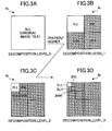
- decompression operations are limited to be performed within a scope of a given code sequence of wavelet coefficients such that the minimum code data be handled necessary for obtain a decompressed image on a specific LL subband with respect to the level-wise wavelet transform technology (see FIGS. 3A through 3D).
- DWT is advantageous in that the image quality is improved at a large-amount compressed zone in comparison to DCT.
- This is one reason for the JPEG2000 is applied as a successor of the conventional JPEG.
- a functional block called "tag processing part 5" is added, in order to perform code formation.
- tag processing part 5" is added, in order to perform code formation.
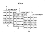
- FIG. 4 illustrates each color component of a color image, which is divided into respective tiles.
- each color component 7R, 7G and 7B (in case the RGB color system is assumed) of the color image is divided into by areas (called tiles) 7Rt, 7Gt and 7Bt.
- Each tile, R00, R01, ..., R15/G00, G01, ..., G15/B00, B01, ..., B15 is used as a basic unit on which data compression/decompression process is performed.
- compression/decompression operation is performed independently for every component, and every tile.
- 2-dimensinal wavelet transform is performed again, and, thus, is further divided into subbands 2LL, 2HL, 2LH and 2HH (62) as shown in FIG. 3C.
- 2-dimensinal wavelet transform is performed, and, thus, is further divided into subbands 3LL, 3HL, 3LH and 3HH (63) as shown in FIG. 3D.
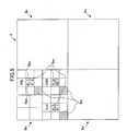
- each coefficient value may be decomposed into bit plains, the order may be determined for the bit planes with respect to the respective pixels or code blocks, and, thus, layers of bit planes may be formed. Namely, from the bit plains of coefficient values, layers based on significances thereof may be created, and coding may be performed for each layer. Then, only a number of layers including the most significant layer (MSB) and several layers subsequent thereto may be coded, and, the remaining layers including the least significant layer may be truncated.
- MSB most significant layer
- coding is performed on the tiles of each component based on probability estimation technique from the contexts and target bits. Thus, coding processing is performed for tile units throughout the components with respect to the relevant color space of the original image.
- image data is produced from a code stream for each tile of each component, according to the process inverse to that at the time of coding described above.
- the tag processing part 5 interprets the tag information attached to the code stream input from the exterior, the code stream is decomposed into code streams on respective tiles of each component, and decoding processing is performed for every code stream on each tile of each component. While positions of pixel value bits to be decoded are determined according to-the sequence based on the tag information, the context is produced from the arrangement of peripheral bits (already decoded) in the inverse quantization part 3.
- the target bits are reproduced, and are put at the relevant pixel position.
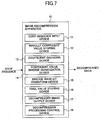
- FIG. 7 illustrates a configuration of a still image decompression apparatus according to an embodiment of the present invention.
- the still image decompression apparatus 10 (simply referred to as an image decompression apparatus, hereinafter), wavelet coefficients in a low-frequency LL subband of the level-wise wavelet transform technology are used for image decompression.
- this apparatus it may be possible to display a large-scale, highly definition still image, or a video with a reduced size at high speed.
- large-scale, high-definition still images or animation formed of successive frames of still images may be displayed on a predetermined region of a display device at a high speed, as will be described in detail.
- the pixel value storing device 16 stores the pixel values having been transformed and decompressed by the inverse wavelet transform device 15.
- the decompression image output device 17 outputs a decompressed image thus stored in the pixel value storing device 16 to a display device, not shown.
- the decompression processing control device 18 controls the above-mentioned respective devices 11 through 17 so as to cause them to perform decompression operation especially for a specific LL subband.
- This decompression apparatus 10 can handle code streams obtained through coding according to a method specified by the JPEG2000 (ISO/IEC FCD 15444-1).
- FIG. 8 illustrates a configuration of a still image decompression apparatus in a second embodiment of the present invention.
- the decompression processing control device 18 as described with reference to FIG. 7 specifically includes a display region specification device 18a and a decomposition determination device 18b.
- the display region specification device 18a is used for specifying a display region in which a reduced image is to be displayed, on the display device in a manner of pixel units for vertical direction and horizontal direction on the display region.
- the display region specification devise 18a calculates a decomposition level such that an image obtained from wavelet coefficient values of the LL subband on the thus-calculated decomposition level be displayed in the specific display region.
- the decomposition determination device 18b may be used for directly specifying the decomposition level, the wavelet coefficient values of the LL subband on the thus-specified decomposition level being then used for display in the display region. For example, when the decomposition level 2 is specified, the wavelet coefficient values on the 2LL subband are used for an image display in the display region (see FIG. 3C).
- interpolation processing for slightly increasing the number of pixels, or thinning out processing for slightly reducing the number of pixels of the image, each well-known, may be employed.
- an actual size reduction rate to be applied may be determined as a power of 1/2 obtained automatically from a LL subband of a decomposition level, as mentioned above.
- a device is provided in the decompression processing control device 18 for specifying a spatial area to be decompressed, a color-space component to be decompressed, or an operation sequence/order in decompression operation.
- a spatial area to be decompressed may be specified with respect to tile units or precinct units.
- the decompression processing control device 18 includes a device by which a control is made on the input I/O or the wavelet coefficient value storing device such that wavelet coefficient values on decomposition levels shallower than or lower than a predetermined level are prevented from being input to the devices and, thus, prevented from undergoing decoding operation and other subsequent operations in the image decompression apparatus 10 (10').
- the decompression processing control device 18 includes a device for performing parallel decompression operations, and also storage for already decompressed frames and/or not-yet decompressed frames, for the purpose of further improving quick display performance and also provision of higher-grade functions.
- parallel decompression operations it becomes possible to improve quick display performance in view of hardware. That is, the further improvement in the speed in quick display performance is realizable by achieving parallel decompression operation for every tile, every color-space component, and every time-axis-sequential frame.
- the present invention can also be embodied in a form of a recording medium in which a software program for making a computer perform the processing procedure of the above-described still image decompression method in order to operate the computer as the above-described still image decompression-apparatus (or each device of this apparatus).
- a CD-ROM a magneto-optical disc
- a DVD-ROM a DVD-ROM
- a FD a flash memory
- various ROM, RAM or the like
- the functions of the still image decompression according to the present invention can be performed by storing this program in such a recording medium, is made to be read by an information processing apparatus, such as a computer, after first writing the program in a recording medium within the information processing apparatus which is then read appropriately therefrom by a CPU for performing the respective steps of the image decompression process according to the present invention.
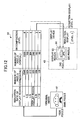
- FIG. 9 is a block diagram illustrating an example of a configuration of a still image decompression apparatus 20 according to a seventh embodiment of the present invention.
- a still image can be displayed in a size-reduced state at high speed with a size-reduction rate as a power of 1/2.
- a code sequence to be processed is obtained by acquiring a code data stored in a storage device 41 of a data storage apparatus 42 through a communications network 40. Data and control data are transmitted through a data bus and a control bus, respectively, in the image decompression apparatus 20.
- the image decompression apparatus 20 includes an I/O port 21 for receiving the code sequence, a code I/O 22 for causing the code to be input through the I/O port 21, and an image I/O 28 through which a decompressed image is output.
- decoders 24 1 , 24 2 , 24 3 acting as decoding devices for color components R, G and B, memories 23 1 , 23 2 , 23 3 acting as decoding devices, inverse-equalizers 25 1 , 25 2 , 25 3 acting as inverse quantization devices, inverse-DWTs 26 1 , 26 2 , 26 3 acting as inverse wavelet transform devices, memories 27 1 , 27 2 , 27 3 acting as pixel value storing devices for storing pixel values (x, y).
- the wavelet coefficient values in a coded form thus obtained ares stored in the memory 23 1 , 23 2 , 23 3 . Then, decoding processing, inverse quantization processing, and inverse wavelet transform are respectively performed one by one on this wavelet coefficient values by the decoders 24 1 , 24 2 , 24 3 , the inverse quantizers 25 1 , 25 2 , 25 3 , and the inverse wavelet transform devices 26 1 , 26 2 , 26 3 .
- the pixel values of a decompressed image obtained by the series of processing are stored in buffer memories 27 1 , 27 2 , 27 3 , finally color conversion processing is performed in an image I/O 28, and the pixel values obtained from the coefficient values on a low frequency LL subband as display image data are output to a display device 43.
- FIG. 10 shows a time required, using the still image decompression apparatus according to the seventh embodiment of the present invention described above, for a display when performing decompression operation required for providing a decompressed image on a specific LL subband.
- Code data applied in this example is a code stream encoded by the JPEG2000 method.
- the advantage of the present invention increases in comparison to the conventional JPEG method. This tendency becomes more remarkable as the original image becomes larger in size or higher in definition/resolution.
- the time required can be reduced by approximately one digit when the reduction rate becomes more than 10.
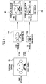
- FIG. 11 illustrates an example in a case of a display of an original image with size reduction at high speed in a display region specified in the still image decompression apparatus shows in FIG. 9.
- the size of the original image 51 is 3200 pixels (width) x 2400 pixels (length) while the display region 53 on the display device 43 is 160 pixels (width) x 120 pixels (length).
- the size of this display region 53 has a rate of size reduction intermediate between 1/16 and 1/32, as shown by an arrow in FIG. 10.
- the decomposition level (level 3) nearest to the display region with respect to the number of pixels, the decomposition level (level 2) smaller than and nearest to the display region with respect to the number of pixels, and the decomposition level (level 3) larger than and nearest to the display region with respect to the number of pixels may be selected, respectively, by calculation.
- a functional module control is performed such that decompression operation of only required for providing a decompressed image on a specific LL subband is performed.
- a CPU 29' performs a control on a code I/O 22 for inputting code data and on a memory 23 for storing wavelet coefficient values, such that only code data needed for decompressing for the specified decomposition level is input or stored there, and, input or storage of the. other parts of code data is avoided.
- the amount of code stream required for the decompression becomes smaller remarkably as the reduction rate becomes larger. Accordingly, by omitting decompression operation on the code stream not required for reproducing a relevant reduced size image, and, also, omitting even inputting or storing this scope of useless part of code stream, it becomes possible to achieve a further quick display of high-definition image.
- FIG. 15 is a block diagram illustrating a configuration of a still image decompression apparatus 20' according to a ninth embodiment of the present invention.
- image reduction rate other than a power of 1/2 can be performed.
- two functional modules i.e., a size change specification device 34 and a size change device 35 are added.
- a magnification operation is performed as a size change operation.
- a size-reduction operation is performed as a size change operation. Magnification and size-reduction operation is specifically achievable by an interpolation operation and a thinning-out operation, respectively, as well known.
- FIG. 16 illustrates a scheme according to the present invention in which a spatial area of an original image to be decompressed is limited only to a central area.
- FIG. 17 illustrates code streams corresponding to the thus-limited area to be decompressed.
- an area 70Rd, 70Gd, and 70Bd (tile numbers 05, 06, 09, and 10) corresponding to a central part of an original image are decompressed from among color component data 70R, 70G and 70B on respective 16 tile areas each for R, G, and B color components.
- the decompressed data 71 is created.
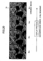
- FIG. 20 illustrates a scheme according to the present invention in which decompression operation order is set according to the order with respect to the decomposition levels in DWT.
- FIG. 20 shows a manner as to how a displayed image changes as the decompression operation proceeds.
- the order of codes in a code stream to be processed is such that, first, a highest decomposition level is decompressed, then, second decomposition level is decompressed, ..., and finally, the lowest/shallowest decomposition level is decompressed.
- wavelet coefficient values on a decomposition level having a larger level number are decoded.
- a vigor image occurs first, and, then, gradually, a finer image occurs.
- an image 75 occurs which corresponds to the original image (finest).
- an order of layers with respect to bit planes may be applied.
- FIG. 21 illustrates a scheme according to the present invention in which an order of display with respect to tiles is applied.
- the display order of the codes corresponding to respective tiles is changed into "the order of spiral" from "the order of raster.”
- the order of the codes themselves in the code stream should be preferably changed according to the order of display. That is, from the order shown at the top of FIG. 21 should be changed into the same shown at the bottom of FIG. 21.
- decompression order can be arbitrarily controlled.
- a process of accessing to the respective codes in the code stream becomes complex, and, thus, decompression speed may be degraded.
- code sequence 77' shown in FIG. 21 is of a new code stream created by thus appropriately re-arranging the packet sequence so that the display order of tiles is changed into the spiral order from the raster order. In this scheme, display speed is prevented from being degraded.
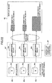
- FIG. 22 illustrates a scheme according to the present invention in which a plurality of animations with reduced sizes are displayed on a same display device at once at high speed.
- animation image data beforehand stored in storage devices 41P, 41Q, and 41R of data storage apparatus 42P, 42Q, and 42R are read therefrom, and are displayed with reduced sizes on the same display device 43 at high speed using an image decompression apparatus 20" according to a tenth embodiment of the present invention.
- FIG. 23 illustrate an image providing system according to an eleventh embodiment of the present invention.
- still image decompression apparatuses according to the present invention are applied for various sizes of display devices at once. Thereby, the same image contents can be viewed through the various sizes of display devices.
- a display device 91 or 94 and an LSI circuit of a PDA 89 or a cellular phone 92 which is a portable device are restricted strictly in terms of physical shape and power consumption.
- the rate of size reduction may be increased accordingly.
- a solution which satisfies both the requirements is to use an only LL subband coefficients of a deep decomposition level in DWT for a mobile device, from among the original image contents.
- a code sequence for the decomposition level 2 is created by a code sequence creation device 87 for the PDA 89 while a code sequence for the decomposition level 3 is created by a code sequence creation device 88 for the cellular phone 92.
- the code data of the original contents is sent to a PC 83, as it is, via a network 80, while, new code sequences for the respective decomposition levels 2 and 3 are created for the PDA 89 and cellular phone 92, which are then sent thereto via radio, respectively. Since decoding operation can be made to the minimum by this scheme, the power consumption can also be effectively minimized.
- the thus-sent data is decompressed by an image decompression apparatus 84 embedded therein.
- an image decompression apparatus 90 or 93 embedded in the display 91 or 94 in the PDA 89 or the cellular phone 92 by receiving via radio the outputs of the code sequence creation device 86, they are decompressed by an image decompression apparatus 90 or 93 embedded in the display 91 or 94 in the PDA 89 or the cellular phone 92.
- Such a code sequence creation apparatus may instead be embedded in the cellular phone, PDA, PC, itself, or the like.
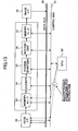
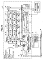
- FIG. 24 is a block diagram showing a configuration of a still image decompression apparatus according to a twelfth embodiment of the present invention.
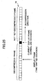
- FIG. 25 illustrates a time-shift display function in this concern.
- the image decompression apparatus includes a hard disk drive 36 as a code sequence storage which stores code data for a specified number of un-decompressed frames, or code data for a specified number of decompressed frames.
- FIG. 26 shows an image providing system according to a thirteenth embodiment of the present invention.
- the image providing system provides a "highly efficient image search apparatus" which employs, in addition to a still image decompression apparatus according to the present invention, the above-mentioned device for achieving parallel operation, and a device 106 for storing code data.
- This system is a system by which a search of many image contents in detail within a short time can be achieved.
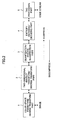
- FIG. 27 is a flow chart illustrating a still image decompression method according to the present invention. As an example, how to display pixel values with size reduction at high speed in an image display region specified on a display device will be described. First, wavelet coefficient values are taken from a scope starting from the deepest decomposition level (having the largest level number) not exceeding a specified decomposition level. Then decoding process and following processes are performed thereon within a scope necessary for a predetermined specified LL subband.
- a display region on a display device is specified (in a step S1). Then, it is. determined whether or not a decomposition level is specified (in a step S2). When it is specified, the specified decomposition level is set in a step S3. Then, when the size of decompressed image to be obtained from an LL subband on the thus-set decomposition level exceeds the size of the display region specified in the step S1, the decomposition level is incremented by 1 so that the size obtained therefrom is one step reduced accordingly (see FIGS. 3A through 3D).
- pixel values are output (in a step S11), and size change processing (in a step S13) is performed if necessary after checking as to whether or not size change is to be performed (in a step S12), and the result is output to a display device (in a step S1).
- size change processing in a step S13
- the decomposition level there are three ways of specifying the decomposition level to be applied. That is, to select the immediately larger one, to select the immediately smaller one, or to select the nearest one.
Landscapes
- Physics & Mathematics (AREA)
- General Physics & Mathematics (AREA)
- Engineering & Computer Science (AREA)
- Theoretical Computer Science (AREA)
- Compression Or Coding Systems Of Tv Signals (AREA)
- Compression Of Band Width Or Redundancy In Fax (AREA)
- Compression, Expansion, Code Conversion, And Decoders (AREA)
- Color Television Systems (AREA)
Applications Claiming Priority (2)
| Application Number | Priority Date | Filing Date | Title |
|---|---|---|---|
| JP2001377294A JP3922919B2 (ja) | 2001-12-11 | 2001-12-11 | 静止画像伸長装置及び静止画像伸長方法 |
| JP2001377294 | 2001-12-11 |
Publications (2)
| Publication Number | Publication Date |
|---|---|
| EP1320073A2 true EP1320073A2 (fr) | 2003-06-18 |
| EP1320073A3 EP1320073A3 (fr) | 2003-08-13 |
Family
ID=19185301
Family Applications (1)
| Application Number | Title | Priority Date | Filing Date |
|---|---|---|---|
| EP20020027615 Ceased EP1320073A3 (fr) | 2001-12-11 | 2002-12-11 | Procedé et dispositif de décompression d'images |
Country Status (3)
| Country | Link |
|---|---|
| US (1) | US7113645B2 (fr) |
| EP (1) | EP1320073A3 (fr) |
| JP (1) | JP3922919B2 (fr) |
Families Citing this family (24)
| Publication number | Priority date | Publication date | Assignee | Title |
|---|---|---|---|---|
| JP3922919B2 (ja) | 2001-12-11 | 2007-05-30 | 株式会社リコー | 静止画像伸長装置及び静止画像伸長方法 |
| JP4189952B2 (ja) * | 2002-11-22 | 2008-12-03 | 株式会社リコー | 符号化復号化装置、符号化復号化用プログラム及び記憶媒体 |
| KR100548383B1 (ko) * | 2003-07-18 | 2006-02-02 | 엘지전자 주식회사 | 이동통신 시스템의 디지털 비디오 신호처리 장치 및 방법 |
| WO2005081539A1 (fr) * | 2004-02-23 | 2005-09-01 | Nec Corporation | Procede et dispositif de codage/decodage de signal bidimensionnel |
| JP2006191159A (ja) * | 2004-12-28 | 2006-07-20 | Canon Inc | 画像処理方法及び画像処理装置 |
| JP4618676B2 (ja) | 2005-04-28 | 2011-01-26 | 株式会社リコー | 構造化文書符号の転送方法、画像処理システム、サーバ装置、プログラム及び情報記録媒体 |
| JP2007235678A (ja) * | 2006-03-02 | 2007-09-13 | Ricoh Co Ltd | 画像符号復号装置 |
| US8081093B2 (en) * | 2006-04-28 | 2011-12-20 | Ricoh Company, Ltd. | Code transforming apparatus and code transforming method |
| US8237830B2 (en) | 2007-04-11 | 2012-08-07 | Red.Com, Inc. | Video camera |
| KR101478380B1 (ko) | 2007-04-11 | 2015-01-06 | 레드.컴 인코포레이티드 | 비디오 카메라 |
| US20090196479A1 (en) * | 2008-01-31 | 2009-08-06 | Raghav Raman | Method and apparatus for computer-aided diagnosis filtered prioritized work item list |
| JP5196181B2 (ja) * | 2008-04-14 | 2013-05-15 | 株式会社リコー | 画像処理システム及び記憶媒体 |
| JP4636474B2 (ja) * | 2008-11-17 | 2011-02-23 | Necカシオモバイルコミュニケーションズ株式会社 | 映像変換装置、映像再生装置、映像変換再生システム及びプログラム |
| KR101515859B1 (ko) * | 2008-12-05 | 2015-05-06 | 삼성전자 주식회사 | 디스플레이장치 및 그 컨텐츠 리스트 표시 방법 |
| JP5158000B2 (ja) * | 2009-04-07 | 2013-03-06 | ソニー株式会社 | 情報処理装置および方法 |
| TWI455571B (zh) | 2009-12-16 | 2014-10-01 | 紅色網域股份有限公司 | 壓縮影像資料基於解析度之格式化 |
| US20120194564A1 (en) | 2011-01-31 | 2012-08-02 | White Christopher J | Display with secure decompression of image signals |
| US9378560B2 (en) * | 2011-06-17 | 2016-06-28 | Advanced Micro Devices, Inc. | Real time on-chip texture decompression using shader processors |
| JP2016508700A (ja) | 2013-02-14 | 2016-03-22 | レッド.コム,インコーポレイテッド | ビデオカメラ |
| US9912930B2 (en) * | 2013-03-11 | 2018-03-06 | Sony Corporation | Processing video signals based on user focus on a particular portion of a video display |
| US10015504B2 (en) * | 2016-07-27 | 2018-07-03 | Qualcomm Incorporated | Compressing image segmentation data using video coding |
| EP3649783B8 (fr) | 2017-07-05 | 2025-04-09 | RED Digital Cinema, Inc. | Traitement de données d'image vidéo dans des dispositifs électroniques |
| JP7242246B2 (ja) * | 2018-10-31 | 2023-03-20 | キヤノン株式会社 | 画像符号化装置、及びこれらの制御方法、並びにプログラム |
| US12230001B2 (en) * | 2022-01-14 | 2025-02-18 | Fraunhofer-Gesellschaft zur Förderung der angewandten Forschung e.V. | Encoder, decoder and related methods |
Citations (1)
| Publication number | Priority date | Publication date | Assignee | Title |
|---|---|---|---|---|
| FR2805640A1 (fr) | 2000-02-28 | 2001-08-31 | Canon Kk | Procede et dispositif de generation d'une image reduite a partir d'une image stockee sous forme compressee dans une base de donnees |
Family Cites Families (20)
| Publication number | Priority date | Publication date | Assignee | Title |
|---|---|---|---|---|
| DE3616607A1 (de) * | 1985-05-17 | 1986-11-20 | Ricoh Co., Ltd., Tokio/Tokyo | Lichtempfindliches material fuer die elektrophotographie |
| US4903016A (en) * | 1987-07-07 | 1990-02-20 | Ricoh Company, Ltd. | Communication control unit |
| NO942080D0 (no) * | 1994-06-03 | 1994-06-03 | Int Digital Tech Inc | Bildekoder |
| US5867602A (en) * | 1994-09-21 | 1999-02-02 | Ricoh Corporation | Reversible wavelet transform and embedded codestream manipulation |
| JP3302246B2 (ja) * | 1995-03-14 | 2002-07-15 | 株式会社リコー | 符号化装置 |
| US6218703B1 (en) * | 1995-07-23 | 2001-04-17 | Ricoh Company, Ltd. | Semiconductor device with control electrodes formed from semiconductor material |
| JP3337599B2 (ja) * | 1995-07-24 | 2002-10-21 | 株式会社リコー | 半導体装置およびインバータ回路並びにコンパレータ並びにa/dコンバータ回路 |
| JP3213222B2 (ja) * | 1995-11-02 | 2001-10-02 | 株式会社リコー | 符号化方法 |
| US6545687B2 (en) * | 1997-01-09 | 2003-04-08 | Canon Kabushiki Kaisha | Thumbnail manipulation using fast and aspect ratio zooming, compressing and scaling |
| US6185340B1 (en) * | 1997-02-18 | 2001-02-06 | Thomson Licensing S.A | Adaptive motion vector control |
| AUPP091197A0 (en) * | 1997-12-15 | 1998-01-08 | Liguori, Vincenzo | Direct manipulation of compressed geometry |
| US6801665B1 (en) * | 1998-09-15 | 2004-10-05 | University Of Maryland | Method and apparatus for compressing and decompressing images |
| US6606095B1 (en) * | 1998-06-08 | 2003-08-12 | Microsoft Corporation | Compression of animated geometry using basis decomposition |
| KR100274397B1 (ko) * | 1998-06-18 | 2000-12-15 | 구자홍 | 타임랩스 영상녹화재생기의 메모리 운용방법 |
| US6778709B1 (en) * | 1999-03-12 | 2004-08-17 | Hewlett-Packard Development Company, L.P. | Embedded block coding with optimized truncation |
| US6934420B1 (en) * | 1999-12-22 | 2005-08-23 | Trident Systems Incorporated | Wave image compression |
| US6985632B2 (en) * | 2000-04-17 | 2006-01-10 | Canon Kabushiki Kaisha | Image processing system, image processing apparatus, and image processing method |
| US6870961B2 (en) * | 2000-11-10 | 2005-03-22 | Ricoh Company, Ltd. | Image decompression from transform coefficients |
| JP2003169333A (ja) * | 2001-09-21 | 2003-06-13 | Ricoh Co Ltd | 符号列作成装置、画像伸長システム、画像伸長装置、画像提供システム、符号列作成方法、プログラム及び記録媒体 |
| JP3922919B2 (ja) | 2001-12-11 | 2007-05-30 | 株式会社リコー | 静止画像伸長装置及び静止画像伸長方法 |
-
2001
- 2001-12-11 JP JP2001377294A patent/JP3922919B2/ja not_active Expired - Fee Related
-
2002
- 2002-12-11 EP EP20020027615 patent/EP1320073A3/fr not_active Ceased
- 2002-12-11 US US10/317,911 patent/US7113645B2/en not_active Expired - Fee Related
Patent Citations (1)
| Publication number | Priority date | Publication date | Assignee | Title |
|---|---|---|---|---|
| FR2805640A1 (fr) | 2000-02-28 | 2001-08-31 | Canon Kk | Procede et dispositif de generation d'une image reduite a partir d'une image stockee sous forme compressee dans une base de donnees |
Also Published As
| Publication number | Publication date |
|---|---|
| JP3922919B2 (ja) | 2007-05-30 |
| US7113645B2 (en) | 2006-09-26 |
| EP1320073A3 (fr) | 2003-08-13 |
| JP2003179759A (ja) | 2003-06-27 |
| US20030169935A1 (en) | 2003-09-11 |
Similar Documents
| Publication | Publication Date | Title |
|---|---|---|
| US7113645B2 (en) | Image decompression apparatus and method | |
| US7352908B2 (en) | Image compression device, image decompression device, image compression/decompression device, program for executing on a computer to perform functions of such devices, and recording medium storing such a program | |
| US7158679B2 (en) | Image compression with tile alignment | |
| US8265402B2 (en) | 2 dimensional signal encoding/decoding method and device | |
| JP2002359850A (ja) | ウェーブレット処理を実行するためのメモリ使用機構 | |
| JP2004221836A (ja) | 画像処理装置、プログラム、記憶媒体及び符号伸長方法 | |
| EP1296287A2 (fr) | Système de traitement de codes d'information d'images | |
| US7627185B2 (en) | Hierarchically compressing and coding and storing image data | |
| JP2004221633A (ja) | 画像処理装置、画像処理用プログラム及び記憶媒体 | |
| JP3952459B2 (ja) | 画像処理装置、プログラム、記憶媒体及び画像処理方法 | |
| JP5950157B2 (ja) | 画像処理装置および方法、並びに、プログラム | |
| US20040161156A1 (en) | Image processing apparatus, method, program and medium storing image processing program | |
| JP4489474B2 (ja) | 画像処理装置、プログラムおよび記録媒体 | |
| EP1635576A1 (fr) | Appareil de traitement d'images et programme de traitement d'images | |
| JP4124436B2 (ja) | 動き量推定装置、プログラム、記憶媒体および動き量推定方法 | |
| JP4040404B2 (ja) | 符号列変換装置及び方法、画像処理装置並びに画像記録装置 | |
| JP4280508B2 (ja) | 位置ずれ補正装置、画像処理装置、プログラム、記憶媒体及び位置ずれ補正方法 | |
| JP4323178B2 (ja) | 検索対象制限装置、画像処理装置、プログラム、記憶媒体及び検索対象制限方法 | |
| JP3961966B2 (ja) | 不要部除去装置、画像処理装置、プログラム、記憶媒体及び不要部除去方法 | |
| JP4093870B2 (ja) | 画像処理装置、プログラムおよび記憶媒体 | |
| JP2004236226A (ja) | 画像伸長方法、画像伸長装置、プログラム及び記憶媒体 | |
| JP4010957B2 (ja) | 画像処理装置、プログラム、記憶媒体および画像形成装置 | |
| JP5244841B2 (ja) | 画像処理装置、画像処理方法、及び画像処理プログラム | |
| Buckley | Color imaging with JPEG 2000 | |
| JP2004289374A (ja) | 画像処理装置、画像処理方法、プログラム、及び記録媒体 |
Legal Events
| Date | Code | Title | Description |
|---|---|---|---|
| PUAI | Public reference made under article 153(3) epc to a published international application that has entered the european phase |
Free format text: ORIGINAL CODE: 0009012 |
|
| 17P | Request for examination filed |
Effective date: 20021211 |
|
| AK | Designated contracting states |
Designated state(s): AT BE BG CH CY CZ DE DK EE ES FI FR GB GR IE IT LI LU MC NL PT SE SI SK TR |
|
| AX | Request for extension of the european patent |
Extension state: AL LT LV MK RO |
|
| PUAL | Search report despatched |
Free format text: ORIGINAL CODE: 0009013 |
|
| AK | Designated contracting states |
Designated state(s): AT BE BG CH CY CZ DE DK EE ES FI FR GB GR IE IT LI LU MC NL PT SE SI SK TR |
|
| AX | Request for extension of the european patent |
Extension state: AL LT LV MK RO |
|
| RIC1 | Information provided on ipc code assigned before grant |
Ipc: 7G 06T 3/40 B Ipc: 7G 06T 9/00 A |
|
| AKX | Designation fees paid |
Designated state(s): DE FR GB IT NL |
|
| 17Q | First examination report despatched |
Effective date: 20061016 |
|
| STAA | Information on the status of an ep patent application or granted ep patent |
Free format text: STATUS: THE APPLICATION HAS BEEN REFUSED |
|
| 18R | Application refused |
Effective date: 20110507 |