EP1320077A2 - Sicherheitsgehäuse - Google Patents
Sicherheitsgehäuse Download PDFInfo
- Publication number
- EP1320077A2 EP1320077A2 EP02026748A EP02026748A EP1320077A2 EP 1320077 A2 EP1320077 A2 EP 1320077A2 EP 02026748 A EP02026748 A EP 02026748A EP 02026748 A EP02026748 A EP 02026748A EP 1320077 A2 EP1320077 A2 EP 1320077A2
- Authority
- EP
- European Patent Office
- Prior art keywords
- chassis
- edge
- functional
- safety
- shell
- Prior art date
- Legal status (The legal status is an assumption and is not a legal conclusion. Google has not performed a legal analysis and makes no representation as to the accuracy of the status listed.)
- Withdrawn
Links
- 238000009423 ventilation Methods 0.000 claims description 29
- 238000007639 printing Methods 0.000 abstract description 24
- 230000007246 mechanism Effects 0.000 abstract description 4
- 230000037431 insertion Effects 0.000 abstract 1
- 238000003780 insertion Methods 0.000 abstract 1
- 238000005192 partition Methods 0.000 description 13
- 230000035515 penetration Effects 0.000 description 7
- 230000017525 heat dissipation Effects 0.000 description 5
- 230000001681 protective effect Effects 0.000 description 5
- 125000006850 spacer group Chemical group 0.000 description 5
- 238000000034 method Methods 0.000 description 3
- 238000013461 design Methods 0.000 description 2
- 230000006870 function Effects 0.000 description 2
- 238000004519 manufacturing process Methods 0.000 description 2
- 239000002184 metal Substances 0.000 description 2
- 230000008569 process Effects 0.000 description 2
- 238000012545 processing Methods 0.000 description 2
- 230000008439 repair process Effects 0.000 description 2
- 238000012546 transfer Methods 0.000 description 2
- JAYCNKDKIKZTAF-UHFFFAOYSA-N 1-chloro-2-(2-chlorophenyl)benzene Chemical compound ClC1=CC=CC=C1C1=CC=CC=C1Cl JAYCNKDKIKZTAF-UHFFFAOYSA-N 0.000 description 1
- 101100084627 Neurospora crassa (strain ATCC 24698 / 74-OR23-1A / CBS 708.71 / DSM 1257 / FGSC 987) pcb-4 gene Proteins 0.000 description 1
- 241000237983 Trochidae Species 0.000 description 1
- 230000015572 biosynthetic process Effects 0.000 description 1
- 230000008859 change Effects 0.000 description 1
- 238000010276 construction Methods 0.000 description 1
- 238000011161 development Methods 0.000 description 1
- 230000018109 developmental process Effects 0.000 description 1
- 238000007599 discharging Methods 0.000 description 1
- 238000005538 encapsulation Methods 0.000 description 1
- 238000007641 inkjet printing Methods 0.000 description 1
- 230000009993 protective function Effects 0.000 description 1
- 238000012552 review Methods 0.000 description 1
- 230000007704 transition Effects 0.000 description 1
- 238000011144 upstream manufacturing Methods 0.000 description 1
Images


Classifications
-
- G—PHYSICS
- G07—CHECKING-DEVICES
- G07B—TICKET-ISSUING APPARATUS; FARE-REGISTERING APPARATUS; FRANKING APPARATUS
- G07B17/00—Franking apparatus
- G07B17/00185—Details internally of apparatus in a franking system, e.g. franking machine at customer or apparatus at post office
- G07B17/00193—Constructional details of apparatus in a franking system
- G07B2017/00233—Housing, e.g. lock or hardened casing
Definitions
- the invention relates to a safety chassis according to the preamble of Claim 1.
- the invention is suitable for devices that have an inner Have security area and from which excess heat to be dissipated. It comes especially in franking machines, Addressing machines and other mail processing devices are used.
- the applicant's thermal transfer franking machine T1000 has one Thermal transfer printhead fixed in the housing for printing of a franking imprint.
- the franking imprint contains one before entered and stored postal information including the Postage data for the transportation of the letter.
- One attached to the housing The compartment is used to hold an exchangeable ribbon cassette (US 4,767,228). While a door leading to the compartment can be opened at any time, access to the security area the printing device is prevented by a safety housing.
- the applicant's JetMail® franking machine is with a base and with a removable meter. Only the latter is through a suitably designed housing protected against misuse.
- the housing of the base which is a mail transport device and includes an inkjet printing device, none Have protective function and can be designed to be repair-friendly. Because the ink tank is separate from the printhead and replaced replacement of the printhead is not necessary. Also do not need any special safety measures for the printhead or to protect the control and data signals, if with a special piezo inkjet printhead a security imprint is printed with a mark, which is a review of the Authenticity of the security imprint allowed (US 6,041,704).
- Inkjet printheads used in the print module (for example in the mymail® by the applicant, in the Personal Post TM by Pitney Bowes and the PortoStar from Neopost).
- An ink tank and a bubble jet print head are built into an interchangeable ink cartridge like it for example from the 1 ⁇ 2 inch ink cartridges from Hewlet Packard is known.
- there must be a hatch in the security housing can be opened by the user to an empty ink cartridge to remove or replace. Because of that made possible Access to the print mechanics and possibly to the printer electronics or contacting the ink cartridge, new opportunities may arise result in the creation of a fake security imprint.
- a security housing is known from EP 1 024 682 A2, which consists of two housing shells, whereby in the assembled state whose side walls overlap with each other. Both housing shells enclose the inner security area with a printed circuit board on which a control is set up. However, there is no heat dissipation forced convection provided. But would ventilation slots Heat dissipation would be provided, then the inner area would either be no longer regarded as secured or the production costs of the Housing shells become unacceptably high.
- the invention has for its object to provide a housing structure to develop internal chassis parts covering the internal security area cover and heat dissipation by forced convection of the Allow airflow to the outside at low manufacturing costs.
- At least one security area is located within the security housing and at least one non-security area.
- Authorized only People such as service technicians, have access to both areas authorized and allowed to open the safety housing.
- Through a Housing construction with internal chassis parts is the security area in the Inside the security housing protected from unauthorized Access.
- a support frame for the print mechanics in the Non-security area is based on at least one functional edge from at least one chassis shell.
- a pressure module is in the support frame movably arranged and mechanically in front of an unauthorized person Access protected. It is assumed that the Functional edges spaced apart from one another are formed on their edge Have ventilation openings, the geometric shape of the edge the functional edges a penetration of tools in the of both Chassis shells enclosed security area impossible.
- the ventilation openings at the edge of the functional edges are arranged in the form of staggered rows, wherein the offset occurs only to the extent that tools penetrate the Security area is made impossible in a straight line. It are ventilation openings on the edge of a first chassis shell and on Edge of functional edges of a second spaced from the first Chassis shell arranged.
- the mutually wrapping edges the chassis shells are shaped at an angle that a Penetration of tools impossible, with at least one of the Functional edges of at least one of the chassis shells U-shaped or reversed ⁇ -shaped or L-shaped. Because of this design are the weight and the forces acting on the print mechanics over the support frame to the chassis upper shell and from the latter over the lower chassis shell is derived from the lower housing section.
- Wise is the print mechanics for the service and for the ink cartridge change easily accessible and good heat dissipation is guaranteed nevertheless, chassis parts cover the inner security area.
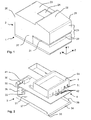
- FIG. 1 shows a perspective view of a franking machine with a removable upper housing part 2, which in the Y direction over a Lower housing part 1 is arranged.
- the franking machine has a divided one Front.
- the front 25, the inbox page 27 and the Show outgoing mail side 28 (not visible) of the upper housing part 2 a slot-shaped opening 21 for a mail item to be franked, which can be fed in the Z direction.
- Below the opening 21 is a separately removable housing part 29 with a letter contact surface.
- the upper side of the housing has a surface 22 that is inclined toward the front side 25 which is suitable, a user interface (not shown) take.
- an opening 24 is arranged on the top of the housing 23, which is in the X direction connects to the inclined housing surface 22 and which of a Back of the housing 26 is limited.
- a flap - not shown in FIG. 1 which covers the aforementioned opening 24 and opened at any time or can be removed.
- a printing module is moved into a position adjacent to the printing position which can remove or replace an ink cartridge.
- an authorized person for example a service technician, may Remove further housing parts.
- After removing the lower part of the housing 1 and top 2 remains a chassis assembly, which one Number of arranged in the Y direction over a lower housing part 1 Has chassis parts.
- FIG. 2 shows a perspective view of a chassis arrangement in FIG exploded view showing an internal security area mechanically protects and heat dissipation through forced convection an air flow to the outside.
- an upper shell 5 is arranged, which to protect and Support purposes is shaped accordingly.
- the upper shell 5 has one Group 51 of external ventilation openings arranged in a row on, which are preferably slit-shaped on the outer edge.
- the lower shell 3 consists of a parallel to the lower housing part 1 Shielding and support plate 31 and from one to the rear of the housing 26 parallel angled rear shielding and support plate part 36, which has at least one opening 39 for discharging a heated one Has airflow to the outside.
- At least one component 41 is in the Y direction Arranged above the circuit board 4 and through an opening 32 in the angled rear shielding and support plate part 36 accessible.
- the aforementioned externally accessible component 41 is, for example an outlet for a power cord.
- At least one group 42 of (Only partially visible) components are in the Y direction above the circuit board 4 and can be placed through the top shell 5 tamper-proof cover. Another group of (not visible) components on the underside of the circuit board 4 is assembled Condition covered by box 3.
- the aforementioned group 42 of components and the further group of Components (not visible) on the underside of the PCB are therefore from completely inaccessible outside and belong to the inner security area.
- the shielding and support plate 31 is parallel to the xz plane and has on its side edges to the inbox page 27 and Outbox side 28 angled and parallel to the xy plane running side edge surfaces 37 and 38.
- the rear shielding and Support plate part 36 is parallel to the yz plane and has the Margins to the inbox page 27 or to the outbox page 28 angled side edges that run parallel to the xy plane 33 or 34 (not visible).
- the lower shell 3 has one of the Shielding and support plate 31 and parallel to the housing front 25 angled and one up to its functional edge parallel to yz plane extending front sheet metal part 35, which one to the xz plane has parallel apron 34.
- the transition to the aforementioned Apron 34 of the lower shell 3 is the one functional edge of the Lower shell 3, which is assembled from the other Functional edge 54 of the upper shell 5 is spaced.
- FIG. 3 shows a perspective view of the upper chassis shell 5, which is shown cut open on one side, in order to make visible a second group 52 of inner ventilation openings arranged in a row, which are preferably incorporated in a slot shape near the functional edge 54 on an inner side wall 53 arranged near the front are.
- the upper chassis shell 5 is delimited to the front by the functional edge 54 and to the rear by a functional edge 541 parallel to it.
- the functional edge 54 of the one upper chassis shell 5 is reversed U-shaped, that is to say ⁇ -shaped, around a first group 51 of ventilation openings on the outer front wall 55 and a (partially visible) second group 52 of ventilation openings on the inner side wall 53, whereby both groups 51 and 52 of ventilation openings near the functional edges are only offset from one another to such an extent as to prevent penetration into the inner region in a straight line.
- the chassis upper shell 5 has a second functional edge 541 offset in the X direction and parallel to the first functional edge 54, which is also designed in the reverse U-shape, ie, ⁇ -shaped, around a first group 511 of ventilation openings on the outside in the X direction lying side wall 551 and a (partially visible) second group 521 at ventilation openings on the inner side wall 531.
- a side wall 57 and 58 shown cut open, delimits the chassis upper shell 5 on the post-stream input and post-stream output side.
- An interior cavity is divided into a lower cavity 50 and an upper cavity 60 by a plate 56 lying parallel to the shielding and support plate 31.
- the lower cavity 50 is provided for receiving billing and control electronics for printing and belongs to the inner security area.
- the upper cavity 60 is provided for receiving a pressure mechanism.
- a box 59 can be arranged on the chassis upper shell 5, which extends, for example, in the X direction to the box rear wall 596 and is delimited in the Z direction, ie downstream, by a box side wall 598 or in the opposite direction, ie upstream, by a box side wall 599 becomes. If the box 59 has a box bottom 590, as shown, then at least one opening 591 for electrical cables is provided in the latter.
- the box 59 has, for example, a greater length in the X direction up to the box rear wall 596 than in the Z direction.
- the box side wall 599 is arranged in the middle of the length in the Z direction on the outer side wall 55 ', all walls preferably having the same height in the Y direction.
- a - cut open - side wall 57 or the side wall 58 are equipped with fastening means 571 and 572 or - not visible - fastening means 581 and 582 in order to fasten the chassis upper shell 5 to the chassis lower shell 3 on the post-flow output side.
- FIG. 4 shows a perspective view of assembled chassis parts 3, 4, 5 and 6.
- the printed circuit board 4 equipped with components from groups 42 and 45 rests on the front of the apron 34 of the lower shell 3 (FIG. 8).
- the chassis upper shell 5 is supported on the printed circuit board 4 with its side walls, a supporting frame 6 for supporting the printing mechanism being arranged as a further chassis part above the functional edges 54, 541 thereof.
- the support frame 6 is delimited by side walls 67 and 68, respectively, on the incoming and outgoing flow side.
- the support frame 6 has a length in the Z direction from one side wall 67 to the other 68, which is divided in the middle by a partition wall 63 into two rectangular boxes, that is to say a box located on the mail flow entry side with a first base area and one on the post flow exit page located box with a second footprint, the box located on the incoming mail side has a smaller footprint than the box located on the outgoing mail side.
- the box located on the mail flow input side is delimited by a rear side wall 62 located in the X direction, the partition wall 63, a front side wall 64 and the side wall 67 and has a base plate 61 with the first base area.
- the dividing wall 63 merges in the X direction into a side wall of the box located on the post-flow exit side, the side wall being flush with the side wall 599 of the box 59 arranged below.
- the box arranged above also has a front side wall 65 and rear side wall 66 located in the X direction. All of the aforementioned walls 62, 63, 64, 65, 66, 67 and 68 are shown cut open in height in order to make parts of the printing mechanism visible.
- a mail piece (not shown) is transported in the transport direction Z by a driven transport drum (shown in FIG. 5), which is arranged opposite at least one spring-loaded counter-pressure roller 11.
- a plate of the housing part 29 having the letter running surface 290 is supported on the first functional edge 54 of the upper chassis shell 5.
- a printing module 7 has a protective cap 73 and carries at least one replaceable ink cartridge 72 which can be fastened on a printing carriage 74.
- a filled envelope is moved by means of a transport drum protruding through an opening 692 in a base plate 611 of the support frame 6 during the printing in the transport direction Z at a predetermined speed.
- the box located on the post stream exit side has a further partition 69 extending in the X direction parallel to the partition 63 to limit the base plate 611 in the Z direction.
- Both partition walls 63, 69 have openings 631, 691 for the transport drum which are spaced apart in the Z direction and close to the printing position.
- a further base plate 612 can be arranged on the same level as the base plate 61 between the partition 69 and the side wall 68 on the side of the mail flow, through which a postal item to be franked, the slot-shaped opening 21 of the upper housing part, not shown - shown in FIG. 1 - is shown 2 inserted, ie fed in the Z direction, is limited in its thickness from the letter running surface 290 in the Y direction.
- the side wall 57 and the side wall 58 (not shown) are equipped with bolts 571 and 581 (not visible) as fastening means.
- the bolt is rotatably mounted in a bearing opening 371 or 381 (not visible) of the side edge surfaces 37 or 38 (not visible), about which the upper chassis shell 5 can be rotated when the other fastening means 572 and 582 (not visible) are released.
- Common fasteners are breakaway screws or lead screws.
- the security area protected in this way can still have a high security area internally. Encapsulation of the high-security area by means of another housing offers additional mechanical protection.
- a security module was developed for such a high-security area, which is equipped with an accounting unit, with a cryptographic unit for securing the postage fee data to be printed and with its own security housing.
- the chassis lower shell 3 has ventilation openings 39 in the rear shielding and support plate part 36 and, if necessary, ventilation openings not shown in the printed circuit board 4 near the component 41.
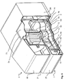
- FIG. 5 On the basis of a perspective view shown in FIG. 5, one of the franking machine cut open on the left is used to cool the Components made possible air flow clarified.
- the upper housing part 2 and housing part 29, the lower chassis shell 3, the upper chassis shell 5 and the box of the chassis part located on the incoming mail stream side 6 are shown cut open. So that the plate with the Letter running surface 290, the bottom plate 61, the rear wall 62 with a U-shaped channel 620, the partition 63 with an opening 631 for the Transport drum 12 in their arrangement to each other at least partially visible.
- the partition 15 is formed on the front inside the lower housing part 1 and extends in Z-direction.
- the airflow is drawn in by a fan 49, whereby flows around the components of the circuit board 4 in the security area become.
- the air flow passes through the second group 511 at ventilation openings in the upper chassis shell 5 and reaches the fan 49, which the exhaust air C through the ventilation openings 39 in the rear Shielding and support plate part 36 presses.
- a second air flow B flows around laterally the circuit board 4 or flows - openings, not shown - in the latter and also reaches the fan 49.
- the air supply takes place via a second channel 152 to a further group - shown in FIG. 7 30 at ventilation openings in the front panel part 35 of the Chassis lower shell 3, the channel 152 through the front panel part 35 of the lower chassis shell 3 and the parallel partition 15 are formed becomes.
- the apron 34 of the lower chassis shell 3 or a corresponding one Part of the circuit board 4 extends up to the partition 15 and limits the second channel 151 up, i.e. in the Y direction.
- the lower housing part 1 limits both channels 151, 152 downwards.
- the back of the housing is 26 formed in a suitable manner, by the dissipated power loss of the components to discharge heated air flow C and with suitable connector sockets to insert pluggable power cord and record telephone and interface cables, etc.
- FIG. 6 shows a perspective view from the right of a cut franking machine, with the upper housing part 2 with the slot 21 for feeding mail on the side wall (not visible) of the inbox and with the side wall 28 on the outgoing mail side, with the housing part 29 on the front side 25 of the upper housing part 2, with the partition wall 15 on the lower housing part 1, with the group 51 of openings in the front side wall 55 of the chassis upper shell 5, with the partition wall 63, with the at least one replaceable ink cartridge 72, with the transport drum 12 and the at least one counter-pressure roller 11 in your Arrangement to one another, the latter being arranged in the space 60 of the upper chassis shell 5, which is separated by the base plate 56 from the space 50 for the components arranged on the printed circuit board 4 in the security area.
- the printing module which is arranged transversely to the transport direction Z, has a printing carriage 74 : Device for printing on a printing medium.
- the protective cap 73 prevents access to the control lines 76 or printer control electronics 75 during printing.
- the protective cap 73 is attached to the printing carriage 74 and closes the aforementioned Opening 24 in the housing, corresponding to the movement of the carriage towards the print position. In any other position in which the The carriage can be brought through the aforementioned opening the protective cap is not or not completely closed. More details to this are the unpublished German patent application 101 49 210.3, which bears the title: Procedure and arrangement for opening a security housing.
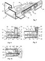
- FIG. 7 shows a perspective view of a detail of a Chassis lower shell 3.
- the air supply of an air flow B takes place from the second channel under the skirt 34 of the lower chassis shell 3 to the second group 30 at ventilation openings in the front panel part 35 of the Chassis lower shell 3.
- the respective side edge surfaces 37 and 38 (not visible) of the chassis lower shell 3 for example bearing openings 371 or 381 (not visible) as a fastening means of the chassis upper shell 5.
- spacers 46, 47, on which a corresponding part of the printed circuit board 4 supports, can be advantageous for air conduction over the surface of the PCB 4 are shared.
- FIG. 8 shows a side view of the chassis arrangement according to FIG. 2, only the one 54 of the two functional edges 54, 54 'of at least two spaced apart chassis shells 3 and 5 being shown. Ventilation openings 30, 51, 52 are formed on their respective edges, the geometric shape of the edge of the functional edges making it impossible for tools to penetrate into the safety area enclosed by the two chassis shells.
- the edge of the functional edges is ⁇ -shaped, resulting in an inner side wall 53 and an outer side wall 55.
- the ventilation openings 51, 52 on Edge of the functional edges arranged in the form of staggered rows are.
- the air flow A flows through the aforementioned ventilation openings 51, 52 on the edge of the functional edges and flows around electronic Components that are in the security area on a circuit board 4 arranged and interconnected.
- the one above the circuit board enclosed interior is by a plate 56 of the chassis shell 5 limited in height and is for receiving components 42 determined.
- the interior enclosed below the circuit board 4 is by a shielding and support plate 31 of the chassis shell 5 in limited in height and is intended for receiving components 45. Additional spacers arranged on the shielding and support plate 31 46, 47 have a clearance and air control function.
- the air flow B flows through the aforementioned ventilation opening 30 and flows around electronic Components 45 in the interior enclosed below the printed circuit board 4 of the security area.
- the chassis lower shell 3, 3 ', 3 " made from a thermally and electrically well conductive metal plate.
- FIG. 9 shows a side view of an alternative chassis arrangement, which is characterized by the edge design and shape of the chassis shells 3 'and 5' differs from the preferred variant according to FIG.
- An extended front panel part takes on their function 35 of the chassis lower shell 3 ', which openings 51' for has the air flow A '.
- the chassis shell 5 ' is supported on the circuit board 4 via a spacer 43 '.
- each of the chassis shells 3 'and 5' are angled at an angle of 90 ° and looped around itself, with a spacer 43 'from each other is observed, which makes penetration of tools impossible.
- An apron 34 as shown in FIG. 8, is omitted here and both air flows A ', B' are taken from a common channel.
- FIG. 10 shows a side view of a further alternative chassis arrangement, which is characterized by the formation and shape of the edge Chassis shells 3 "and 5" of the preferred variant according to FIGS. 8 or 9 differs. It is contemplated that at least two of each other spaced chassis parts and at least L-shaped Have functional edges with ventilation openings on their edge, whereby the ventilation openings of the functional edges of the at least two spaced apart from each other are. It is envisaged that the edges of the chassis shells 3 " and 5 "wrap around each other while being shaped at an angle are that makes penetration of tools impossible.
- each of the chassis shells For example are the edges of each of the chassis shells at an angle of 90 ° angled and looping around, with a spacer 43 " Distance from each other is maintained, which is a penetration of tools makes impossible.
- the interior enclosed above the circuit board, which is limited in height by a plate 56 "of the chassis shell 5" is maximum when the plate 56 "is at the same height as that Functional edge 54 "lies and seamlessly merges into one or the same the functional edge is 54 ".
- the invention is not limited to the present embodiment.
- a large number of an alternative chassis arrangement is conceivable within the scope of the claims, the aforementioned functional edges being designed differently and having ventilation openings on their edge with a more or less labyrinth-like edge structure, so that penetration of tools in a straight line is made impossible.
- further other embodiments of the invention can be developed or used, starting from the same basic idea of the invention, which are encompassed by the appended claims.
Landscapes
- Physics & Mathematics (AREA)
- General Physics & Mathematics (AREA)
- Casings For Electric Apparatus (AREA)
- Accessory Devices And Overall Control Thereof (AREA)
- Aiming, Guidance, Guns With A Light Source, Armor, Camouflage, And Targets (AREA)
Abstract
Description
- Figur 1,
- perspektivische Ansicht einer Frankiermaschine,
- Figur 2,
- perspektivische Ansicht einer Chassisanordnung,
- Figur 3,
- perspektivische Ansicht einer Chassisoberschale,
- Figur 4,
- perspektivische Ansicht von montierten Chassisteilen,
- Figur 5,
- perspektivische Ansicht von links einer aufgeschnittenen Frankiermaschine,
- Figur 6,
- perspektivische Ansicht von rechts einer aufgeschnittenen Frankiermaschine,
- Figur 7,
- perspektivische Ansicht eines Details einer Chassisunterschale,
- Figur 8,
- Seitenansicht der Chassisanordnung nach Fig.2,
- Figur 9,
- Seitenansicht einer alternativen Chassisanordnung,
- Figur 10,
- Seitenansicht einer weiteren alternativen Chassisanordnung.
Eine - aufgeschnitten dargestellte - Seitenwand 57 bzw. die Seitenwand 58 sind mit Befestigungsmitteln 571 und 572 bzw. - nicht sichtbaren --Befestigungsmitteln 581 und 582 ausgestattet, um die Chassisoberschale 5 poststromausgangsseitig an der Chassisunterschale 3 zu befestigen.
Ein Druckmodul 7 hat eine Schutzkappe 73 und trägt mindestens eine auswechselbare Tintenkartusche 72, die auf einem Druckwagen 74 befestigbar ist. Ein gefülltes Briefkuvert wird mittels einer durch eine Öffnung 692 in einer Bodenplatte 611 des Stützrahmens 6 ragenden Tansporttrommel während des Druckens in Transportrichtung Z mit einer vorbestimmten Geschwindigkeit bewegt. Der an der Poststromausgangsseite gelegene Kasten weist parallel zur Trennwand 63 eine weitere sich in X-Richtung erstreckende Trennwand 69 zum Begrenzen der Bodenplatte 611 in Z-Richtung auf. Beide Trennwände 63, 69 weisen in der Nähe des Druckposition gegenüberliegenden in Z-Richtung beabstandete Öffnungen 631, 691 für für die Transporttrommel auf. Zwischen der Trennwand 69 und der poststromausgangsseitigen Seitenwand 68 kann auf der gleichen Ebene wie die Bodenplatte 61 eine weitere Bodenplatte 612 angeordnet sein, durch welche ein zu frankierendes Postgut, das in nicht gezeigter Weise - in der Fig. 1 gezeigte - schlitzförmige Öffnung 21 des Gehäuseoberteils 2 gesteckt, d.h. in Z-Richtung zugeführt wird, in seiner Dicke ab der Brieflauffläche 290 in Y-Richtung begrenzt wird.
Die Seitenwand 57 bzw. die - nicht dargestellte - Seitenwand 58 sind mit Bolzen 571 bzw. 581 (nicht sichtbar) als Befestigungsmittel ausgestattet. Der Bolzen ist in einer Lageröffnung 371 bzw 381 (nicht sichtbar) der Seitenrandflächen 37 bzw. 38 (nicht sichtbar) drehbar gelagert, um welche die Chassisoberschale 5 drehbar ist, wenn die übrigen Befestigungsmittel 572 und 582 (nicht sichtbar) gelöst sind. Übliche Befestigungsmittel sind Wegbrechschrauben oder verplombte Schrauben.
Die Chassisunterschale 3 hat Lüftungsöffnungen 39 im rückwärtigen Abschirm- und Stützblechteil 36 und ggf. nicht gezeigte Lüftungsöffnungen in der Leiterplatte 4 nahe dem Bauteil 41.
Das querbeweglich zur Transportrichtung Z angeordnete Druckmodul hat neben der mindestens einen auswechselbaren Tintenkartusche 72, die in der Druckposition zum Teil in die Transporttrommel 73 hineinragt, einen Druckwagen 74. Nähere Ausführungen dazu sind der nicht vorveröffentlichten deutschen Patentanmeldung 100 32 855.5 entnehmbar, welche den Titel trägt: Vorrichtung zum Bedrucken eines Druckträgers.
An deren jeweiligen Rändern sind Lüftungsöffnungen 30, 51, 52 ausgebildet, wobei die geometrische Form des Randes der Funktionskanten ein Eindringen von Werkzeugen in den von beiden Chassisschalen eingeschlossenen Sicherheitsbereich unmöglich macht. Der Rand der Funktionskanten ist ∩-förmig ausgebildet, wobei sich eine innere Seitenwand 53 und eine äußere Seitenwand 55 ergibt.
Es ist eine Vielzahl einer alternativen Chassisanordnung im Rahmen der Ansprüche denkbar, wobei die vorgenannten Funktionskanten in der Form unterschiedlich ausgeführt sind und Lüftungsöffnungen an ihrem Rand aufweisen mit einer mehr oder weniger labyrintartigen Randstruktur, so das ein Eindringen von Werkzeugen auf geradlinigem Wege unmöglich gemacht wird. So können offensichtlich weitere andere Ausführungen der Erfindung entwickelt bzw. eingesetzt werden, die vom gleichen Grundgedanken der Erfindung ausgehend, die von den anliegenden Ansprüchen umfaßt werden.
Claims (7)
- Sicherheitschassis für einen Sicherheitsbereich im Inneren eines Sicherheitsgeehäuses (1, 2), mit einem Stützrahmen (6) für die Druckmechanik im Nichtsicherheitsbereich, wobei ein Druckmodul (7) im Stützrahmen (6) beweglich angeordnet und mechanisch vor einem unberechtigten Zugriff geschützt ist,
gekennzeichnet dadurch, dass sich der Stützrahmen (6) auf mindestens einer Funktionskante (541, 541', 541") von mindestens einer Chassisschale (5, 5', 5") abstützt, wobei mindestens zwei voneinander beabstandete Chassisschalen (3, 3', 3", 5, 5', 5") den Sicherheitsbereich umgeben, dass die mindestens eine Funktionskante (54, 54', 54", 541, 541', 541") an ihrem Rand ausgebildete Lüftungsöffnungen (51, 51', 51", 52, 52', 52", 511, 511', 511", 521, 521', 521") aufweist, wobei die geometrische Form des Randes der Funktionskante (54, 54', 54", 541, 541', 541") ein Eindringen von Werkzeugen in den von beiden Chassisschalen (3, 3', 3", 5, 5', 5") eingeschlossenen Sicherheitsbereich unmöglich macht. - Sicherheitschassis, nach Anspruch 1, gekennzeichnet dadurch, dass die Lüftungsöffnungen am Rand der Funktionskanten (54, 54', 54" bzw. 541, 541', 541") in Form von zueinander versetzten Reihen (51, 51', 51" und 52, 52', 52" bzw. 511, 511', 511" und 521, 521', 521") angeordnet sind.
- Sicherheitschassis, nach einem der Ansprüche 1 bis 2, gekennzeichnet dadurch, daß Lüftungsöffnungen (50, 50', 50") am Rand (35, 35', 35") der ersten Chassisschale (3, 3', 3") und am Rand von Funktionskanten (54, 54', 54" bzw. 541, 541', 541") einer zweiten von der ersten beabstandeten Chassisschale (5, 5', 5") vorgesehen sind.
- Sicherheitschassis, nach Anspruch 1, gekennzeichnet dadurch, dass sich die Ränder der Chassisschalen (3, 3', 3", 5, 5', 5") gegenseitig umschlingen und in dabei in einem Winkel geformt sind, der ein Eindringen von Werkzeugen unmöglich macht.
- Sicherheitschassis, nach Anspruch 1, gekennzeichnet dadurch, dass mindestens eine der Funktionskanten L-förmig gestaltet ist.
- Sicherheitschassis, nach Anspruch 1, gekennzeichnet dadurch, dass mindestens eine der Funktionskanten mindestens einer der Chassisschalen U-förmig bzw. umgekehrt ∩-förmig gestaltet ist.
- Sicherheitschassis, nach Anspruch 2, gekennzeichnet dadurch, dass der Versatz nur soweit erfolgt, das ein Eindringen von Werkzeugen in den Sicherheitsbereich auf geradlinigem Wege unmöglich gemacht wird.
Applications Claiming Priority (2)
| Application Number | Priority Date | Filing Date | Title |
|---|---|---|---|
| DE10164526A DE10164526A1 (de) | 2001-12-15 | 2001-12-15 | Sicherheitschassis |
| DE10164526 | 2001-12-15 |
Publications (2)
| Publication Number | Publication Date |
|---|---|
| EP1320077A2 true EP1320077A2 (de) | 2003-06-18 |
| EP1320077A3 EP1320077A3 (de) | 2004-01-21 |
Family
ID=7711179
Family Applications (1)
| Application Number | Title | Priority Date | Filing Date |
|---|---|---|---|
| EP02026748A Withdrawn EP1320077A3 (de) | 2001-12-15 | 2002-12-02 | Sicherheitsgehäuse |
Country Status (3)
| Country | Link |
|---|---|
| US (1) | US6739717B2 (de) |
| EP (1) | EP1320077A3 (de) |
| DE (1) | DE10164526A1 (de) |
Families Citing this family (5)
| Publication number | Priority date | Publication date | Assignee | Title |
|---|---|---|---|---|
| CN1645994A (zh) * | 2004-01-20 | 2005-07-27 | 迪尔阿扣基金两合公司 | 塑料外壳 |
| DE202004010858U1 (de) * | 2004-07-06 | 2004-11-04 | Francotyp-Postalia Ag & Co. Kg | Anordnung einer Kommunikationseinheit in einem Gerät |
| DE202004016611U1 (de) * | 2004-10-27 | 2005-02-10 | Francotyp-Postalia Ag & Co. Kg | Sicherheitsgehäuse mit Lüftungsöffnungen |
| US20090116187A1 (en) * | 2007-11-06 | 2009-05-07 | Cisco Technology, Inc. | Opacity enclosure for fips 140-2 |
| DE202012005904U1 (de) | 2012-06-15 | 2012-07-16 | Francotyp-Postalia Gmbh | Frankiermaschine |
Citations (3)
| Publication number | Priority date | Publication date | Assignee | Title |
|---|---|---|---|---|
| EP0265285A2 (de) * | 1986-10-23 | 1988-04-27 | Instrument Specialities Co., Inc. | Elektromagnetische Abschirmung für gedrucke Leiterplatte |
| GB2209436A (en) * | 1987-08-28 | 1989-05-10 | Motorola Inc | Method and apparatus for providing emi/rfi shielding of an infrared energy reflow soldered device |
| US5400949A (en) * | 1991-09-19 | 1995-03-28 | Nokia Mobile Phones Ltd. | Circuit board assembly |
Family Cites Families (10)
| Publication number | Priority date | Publication date | Assignee | Title |
|---|---|---|---|---|
| GB2169875B (en) * | 1985-01-19 | 1988-09-14 | Francotyp Postalia Gmbh | Improvements in ribbon cassettes |
| FR2664722B1 (fr) * | 1990-07-10 | 1992-09-18 | Alcatel Satmam | Machine a affranchir a tete d'impression amovible. |
| US5087794A (en) * | 1990-07-19 | 1992-02-11 | Honeywell Inc. | Thermostat guard |
| DE4033999A1 (de) * | 1990-10-25 | 1992-04-30 | Siemens Ag | Schaltungsmodul mit sicherheitsgehaeuse |
| US5427023A (en) * | 1991-05-20 | 1995-06-27 | Pitney Bowes Inc. | Mailing machine having a disposable inking cartridge |
| GB9500074D0 (en) * | 1995-01-04 | 1995-03-01 | Neopost Ltd | Franking machine system |
| GB9709049D0 (en) | 1997-05-02 | 1997-06-25 | Neopost Ltd | Postage meter with removable print head |
| EP0881086B1 (de) * | 1997-05-28 | 2005-04-27 | Neopost Limited | Sicheres Drückgerät mit einem abnehmbaren Druckkopf |
| DE19748954A1 (de) | 1997-10-29 | 1999-05-06 | Francotyp Postalia Gmbh | Verfahren für eine digital druckende Frankiermaschine zur Erzeugung und Überprüfung eines Sicherheitsabdruckes |
| GB9902056D0 (en) | 1999-01-29 | 1999-03-24 | Neopost Ltd | Secure housing |
-
2001
- 2001-12-15 DE DE10164526A patent/DE10164526A1/de not_active Ceased
-
2002
- 2002-12-02 EP EP02026748A patent/EP1320077A3/de not_active Withdrawn
- 2002-12-16 US US10/320,128 patent/US6739717B2/en not_active Expired - Fee Related
Patent Citations (3)
| Publication number | Priority date | Publication date | Assignee | Title |
|---|---|---|---|---|
| EP0265285A2 (de) * | 1986-10-23 | 1988-04-27 | Instrument Specialities Co., Inc. | Elektromagnetische Abschirmung für gedrucke Leiterplatte |
| GB2209436A (en) * | 1987-08-28 | 1989-05-10 | Motorola Inc | Method and apparatus for providing emi/rfi shielding of an infrared energy reflow soldered device |
| US5400949A (en) * | 1991-09-19 | 1995-03-28 | Nokia Mobile Phones Ltd. | Circuit board assembly |
Also Published As
| Publication number | Publication date |
|---|---|
| DE10164526A1 (de) | 2003-06-18 |
| US20030112314A1 (en) | 2003-06-19 |
| EP1320077A3 (de) | 2004-01-21 |
| US6739717B2 (en) | 2004-05-25 |
Similar Documents
| Publication | Publication Date | Title |
|---|---|---|
| EP1653790B1 (de) | Sicherheitsgehäuse mit Lüftungsöffnungen | |
| EP1300807B1 (de) | Verfahren und Anordnung zum Öffnen eines Sicherheitsgehäuses | |
| EP1320076B1 (de) | Anordnung zum Schutz eines Druckmoduls in einem Postverarbeitungsgerät | |
| DE3729342A1 (de) | Sicherheitsdrucker fuer ein wertdrucksystem | |
| DE69510833T2 (de) | Frankiermaschine mit einem gesicherten und einem ungesicherten Modul | |
| DE10011192A1 (de) | Frankiermaschine mit abgesichertem Druckkopf | |
| EP0276626A2 (de) | Drucker für eine Vielzahl von unterschiedlichen Druckobjekten | |
| DE69923408T2 (de) | Verfahren und Vorrichtung zur dynamischen Bestimmung der Druckposition für ein Postwertzeichen in einen Dokument | |
| DE69829911T2 (de) | Sicheres Drückgerät mit einem abnehmbaren Druckkopf | |
| EP2073173B1 (de) | Vorrichtung zum Wechseln von Tintenkartuschen | |
| EP1103924A2 (de) | Verfahren zum Schutz eines Gerätes vor einem Betreiben mit unzulässigem Verbrauchsmaterial und Anordnung zur Durchführung des Verfahrens | |
| DE19912780A1 (de) | Anordnung für ein Sicherheitsmodul | |
| DE19912781A1 (de) | Verfahren zum Schutz eines Sicherheitsmoduls und Anordnung zur Durchführung des Verfahrens | |
| EP1320077A2 (de) | Sicherheitsgehäuse | |
| DE3627124A1 (de) | Frankiermaschinen-verriegelungssystem | |
| DE3407633A1 (de) | Zusatzdruckvorrichtung fuer eine frankiermaschine | |
| DE69803975T2 (de) | Gesicherter digitaler Frankier-Druckmodul | |
| DE19958949A1 (de) | Verfahren zum automatischen Bestellen von Verbrauchsmaterial und Anordnung zur Durchführung des Verfahrens | |
| DE3636353C1 (de) | Plombierbares Gehaeuse fuer Taxameter-Drucker und Taxameter-Datenspeichermodule | |
| DE3685547T2 (de) | Abdeckanordnung fuer frankiermaschine. | |
| EP1061479A2 (de) | Anordnung und Verfahren zur Generierung eines Sicherheitsabdruckes | |
| EP1615174B1 (de) | Frankiermaschine mit einer Kommunikationseinheit | |
| DE10149210A1 (de) | Verfahren und Anordnung zum Öffnen eines Sicherheitsgehäuses | |
| DE202018102465U1 (de) | Gutverarbeitungsgerät mit einem Tintenstrahldruckkopf | |
| DE20211108U1 (de) | Anordnung eines Sicherheitsmoduls in einer Frankiermaschine |
Legal Events
| Date | Code | Title | Description |
|---|---|---|---|
| PUAI | Public reference made under article 153(3) epc to a published international application that has entered the european phase |
Free format text: ORIGINAL CODE: 0009012 |
|
| AK | Designated contracting states |
Designated state(s): AT BE BG CH CY CZ DE DK EE ES FI FR GB GR IE IT LI LU MC NL PT SE SI SK TR |
|
| AX | Request for extension of the european patent |
Extension state: AL LT LV MK RO |
|
| PUAL | Search report despatched |
Free format text: ORIGINAL CODE: 0009013 |
|
| AK | Designated contracting states |
Kind code of ref document: A3 Designated state(s): AT BE BG CH CY CZ DE DK EE ES FI FR GB GR IE IT LI LU MC NL PT SE SI SK TR |
|
| AX | Request for extension of the european patent |
Extension state: AL LT LV MK RO |
|
| RIC1 | Information provided on ipc code assigned before grant |
Ipc: 7H 05K 5/02 B Ipc: 7G 07B 17/04 A |
|
| 17P | Request for examination filed |
Effective date: 20040204 |
|
| AKX | Designation fees paid |
Designated state(s): AT BE BG CH CY CZ DE DK EE ES FI FR GB GR IE IT LI LU MC NL PT SE SI SK TR |
|
| 17Q | First examination report despatched |
Effective date: 20041022 |
|
| RAP1 | Party data changed (applicant data changed or rights of an application transferred) |
Owner name: FRANCOTYP-POSTALIA GMBH |
|
| STAA | Information on the status of an ep patent application or granted ep patent |
Free format text: STATUS: THE APPLICATION IS DEEMED TO BE WITHDRAWN |
|
| 18D | Application deemed to be withdrawn |
Effective date: 20100626 |