EP1320092B1 - Appareil pour l'orientation des cassettes dans des magasins et méthode d'utilisation - Google Patents
Appareil pour l'orientation des cassettes dans des magasins et méthode d'utilisation Download PDFInfo
- Publication number
- EP1320092B1 EP1320092B1 EP02027077A EP02027077A EP1320092B1 EP 1320092 B1 EP1320092 B1 EP 1320092B1 EP 02027077 A EP02027077 A EP 02027077A EP 02027077 A EP02027077 A EP 02027077A EP 1320092 B1 EP1320092 B1 EP 1320092B1
- Authority
- EP
- European Patent Office
- Prior art keywords
- cartridge
- storage
- orientation
- projection
- magazine
- Prior art date
- Legal status (The legal status is an assumption and is not a legal conclusion. Google has not performed a legal analysis and makes no representation as to the accuracy of the status listed.)
- Expired - Lifetime
Links
- 238000000034 method Methods 0.000 title claims description 5
- 238000003780 insertion Methods 0.000 claims description 8
- 230000037431 insertion Effects 0.000 claims description 8
- 230000000903 blocking effect Effects 0.000 claims description 3
- 238000013500 data storage Methods 0.000 description 1
- 238000010586 diagram Methods 0.000 description 1
- 238000004519 manufacturing process Methods 0.000 description 1
Images


Classifications
-
- G—PHYSICS
- G11—INFORMATION STORAGE
- G11B—INFORMATION STORAGE BASED ON RELATIVE MOVEMENT BETWEEN RECORD CARRIER AND TRANSDUCER
- G11B15/00—Driving, starting or stopping record carriers of filamentary or web form; Driving both such record carriers and heads; Guiding such record carriers or containers therefor; Control thereof; Control of operating function
- G11B15/675—Guiding containers, e.g. loading, ejecting cassettes
- G11B15/68—Automatic cassette changing arrangements; automatic tape changing arrangements
- G11B15/682—Automatic cassette changing arrangements; automatic tape changing arrangements with fixed magazines having fixed cassette storage cells, e.g. in racks
- G11B15/6835—Automatic cassette changing arrangements; automatic tape changing arrangements with fixed magazines having fixed cassette storage cells, e.g. in racks the cassettes being transferred to a fixed recorder or player using a moving carriage
-
- G—PHYSICS
- G11—INFORMATION STORAGE
- G11B—INFORMATION STORAGE BASED ON RELATIVE MOVEMENT BETWEEN RECORD CARRIER AND TRANSDUCER
- G11B23/00—Record carriers not specific to the method of recording or reproducing; Accessories, e.g. containers, specially adapted for co-operation with the recording or reproducing apparatus ; Intermediate mediums; Apparatus or processes specially adapted for their manufacture
- G11B23/02—Containers; Storing means both adapted to cooperate with the recording or reproducing means
- G11B23/023—Containers for magazines or cassettes
-
- G—PHYSICS
- G11—INFORMATION STORAGE
- G11B—INFORMATION STORAGE BASED ON RELATIVE MOVEMENT BETWEEN RECORD CARRIER AND TRANSDUCER
- G11B17/00—Guiding record carriers not specifically of filamentary or web form, or of supports therefor
- G11B17/22—Guiding record carriers not specifically of filamentary or web form, or of supports therefor from random access magazine of disc records
- G11B17/225—Guiding record carriers not specifically of filamentary or web form, or of supports therefor from random access magazine of disc records wherein the disks are transferred from a fixed magazine to a fixed playing unit using a moving carriage
Definitions
- the present application relates generally to storage magazines for storing cartridges, and in particular to an apparatus for assuring a predetermined orientation of a cartridge in the storage magazine, for example, in an automated cartridge handling apparatus, as well as to a method.
- US-A 5,933,396 discloses a cartridge storage magazine, comprising walls defining slots for the storage of a cartridge, a projection extending from a rear wall inside at least one of said slots for extension into a recess in the cartridge if the cartridge is inserted into the slot in a first orientation, said projection blocking full insertion of the cartridge in the storage slot if the cartridge is in a second orientation.
- This cartridge storage magazine is to be used in a cartridge handling apparatus.
- Such an apparatus is equipped with a cartridge handling device which selectively removes a cartridge from a storage slot in the storage magazine and transfers it into a load opening in the drive.
- the cartridge handling device is arranged in the middle of two opposite cartridge storage magazines which have the slots' openings facing each other.
- the cartridge magazine on the left side may not be identical with the one on the right side if the transferring device is a translational one like a shuttle which grabs a cartridge as it is oriented and transfers it to the load opening in the drive.
- the transferring device is a translational one like a shuttle which grabs a cartridge as it is oriented and transfers it to the load opening in the drive.
- EP-A 1 107 245 discloses a rotatable cartridge engaging assembly.
- a cartridge handling system comprises a first array of cartridge locations oriented along a first plane AA and a second array of cartridge locations oriented along a second plane BB, which is parallel to the first plane AA.
- the cartridge locations are comprised of cartridge storage slots and read/write drives.
- Each of the cartridges within an array of cartridge locations are oriented such that the front of the cartridge is facing outwardly toward the cartridges in the opposite array.
- the cartridge engaging assembly is adapted to rotate in order to access the cartridges and read/write drives allocated along either plane AA, BB. As the engaging assembly is able to rotate it is able to bring the cartridge into the proper position before loading into the drive.
- An apparatus and method is provided for assuring a predetermined orientation of a cartridge in a cartridge storage magazine.
- a projection is provided within a cartridge storage space for preventing full insertion of a mis-oriented cartridge.
- Embodiments of the invention find utility in automated cartridge handling devices. such as for loading and unloading of cartridges into cartridge drives.
- an automated cartridge handling apparatus 10 including a housing 12 which encloses a tape drive 14 for recording and playback of magnetic tape cartridges 22. Transfer of the magnetic tape cartridges 22 into and out of the recording drive 14 is accomplished by a cartridge handling shuttle 16.
- the cartridge handling shuttle 16 is positioned between two cartridge storage magazines 18 and 20 and is capable of movement to access the drive 14 and the storage slots in the magazines 18 and 20.
- the cartridge handling shuttle 16 selectively removes a cartridge 22 from a storage slot in the storage magazine 18 or 20 and transfers it into a load opening in the drive 14.
- Data or other information is either recorded onto a tape in the cartridge 22 or is read from the tape in the cartridge 22 by the drive, or both, and the cartridge 22 is then removed from the drive 14 and moved by the cartridge handling shuttle 16 into a storage slot in the storage magazine 18 or 20.
- the cartridge 22 may be carried to the end 24 by the shuttle 16 where it may be removed via a mail slot 26 opening at the end 24.
- a cartridge 22 may also be inserted via the mail slot 26 for receipt by the shuttle 16.
- the mail slot 26 is sized to accommodate a single cartridge 22 and preferably has a hinged door which keeps the opening closed when not in use. This permits single cartridges 22 to be inserted or transferred out.
- openings 28 are provided in the end 24 through which the storage magazines 18 and 20 are removed.
- the openings 28 permit each of the magazines 18 and 20 to be removed for filling without removing the device from its mounting rack.
- a door is provided over each of the openings 28 which is normally closed.
- the openings 28 are of a size so that the magazine 18 or 20 may fit therethrough when empty or when the magazine contains fully inserted cartridges 22, but the magazine will not fit through the opening 28 if a cartridge 22 is not fully inserted into the magazine 18 or 20. This prevents improperly loaded magazines 18 or 20 from being put into the device, as will become apparent hereinafter.
- the storage magazines 18 and 20 each include eight storage slots, arranged two high by four wide.
- a single drive 14 is provided in the housing 12. It is, of course, possible that the storage magazines 18 and 20 may be wider or narrower, taller or shorter, having more or less storage slots. It is also contemplated that a storage magazine may be provided on only one side of the cartridge handling shuttle 16. It is further contemplated to provide additional tape drive units 14, for example, stacked one above another.
- the cartridges 22 are shown in the relative positions where they are stored in the storage magazines 18 and 20.
- the cartridges 22 For proper loading of the cartridges into the drive 14, the cartridges 22 must have a pre-defined orientation as indicated by the arrow on the cartridges 22.
- the cartridge handling shuttle 16 of the present embodiment is unable to determine the orientation of the cartridge and so may attempt to load the improperly oriented cartridge into the drive.
- An improperly oriented cartridge 22 will not work if loaded into the drive 14, and may even cause problems. For example, if the cartridge is positioned back-for-front when loaded into the drive, the drive may jam or fail.
- the present invention helps to prevent this, by ensuring proper orientation of the cartridges 22.
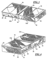
- FIG 3 two of the storage slots of the storage magazine 18 of Figure 1.
- Each of the two storage slots 30 and 34 has contained therein a cartridge 22.
- the cartridge 22a is oriented in the proper orientation for later insertion into the tape drive 14.
- a proper orientation of the cartridge 22 means that a front side is inserted first.
- the front side has recess 40 and adjacent to the recess 40 is a lower edge portion 54. Inserting the cartridge 22 with it's front side first means inserting in a first orientation.
- the cartridge 22a is fully inserted into the slot 30 and a snap 32 engages a top comer edge of the cartridge 22a to lock the cartridge 22a in place.
- the storage slot 34 has the cartridge 22b inserted in an opposite orientation, i.eback-for-front.
- the back side of the cartridge 22 is opposite the front side and has a recess 42.
- inserting the cartridge in a second orientation means first inserting the back side, i.e. the side with recess 42. An attempt by the shuttle to load this cartridge 22b into the drive 14 would result in failure of the device and possibly damage.
- the cartridge 22b is prevented from being fully inserted into the storage slot 34.
- the snap lock 32 for the slot 34 is prevented from engagement with the top corner edge of the cartridge 22b.
- a proper orientation of the cartridge 22 means that a front side is inserted first.
- the front side has a recess 40 and adjacent to the recess 40 is a lower edge portion 54. Inserting the cartridge 22 with it's front side first means inserting in a first orientation.
- the back side of the cartridge 22 is opposite the front side and has a recess 42.
- inserting the cartridge in a second orientation means first inserting the back side, i.e. the side with recess 42.
- the cartridges are prevented from being improperly loaded in a fully inserted position into the storage slots. Only properly oriented cartridges 22 can be fully inserted into the slots. Thus, during the manual cartridge loading of the magazine, the cartridges may not be fully inserted in the wrong orientation.
- the disclosed embodiment prevents human error during the manual loading of the magazine from resulting in a subsequent failure of the device due to an improperly oriented cartridge.
- the dimensions of the opening 28 in the front panel 24 of the housing 12 is such that it can only accept magazines into which the cartridges are fully inserted, and thus properly oriented. Any cartridge which has an improper orientation and so projects from the magazine would cause the magazine to not fit into the magazine loading opening 28.
- the front loading of the magazines 18 and 20 enables the magazines to be removed, emptied of cartridges, refilled, and re-inserted into the apparatus without unmounting of the present apparatus, such as from a mounting rack.
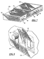
- FIG 4 is shown a rear view of the two storage slots 30 and 34 of Figure 3 with the cartridges 22a and 22b positioned therein.
- a back wall of the storage magazine 18 is indicated ina phantom so that an alignment projection 36 which extends into each of the slots 30 and 34 is visible.
- the projections 36 are positioned with an extension 38 directed upwardly This direction corresponds to a first orientation of the projection 36. In this position, the projection 36 extends into a recess 40 in a side of the cartridge 22a. This permits the cartridge 22a to be inserted fully into the slot 30 as the lower edge portion 54 slides under the upwardly directed projection 36 so that the snap lock 32 engages.
- the cartridge 22b is inserted into the slot 34 in an incorrect orientation, i.e.
- the cartridge 22b has a recess 42 on the side face in the vicinity of the projection 36; however, since the projection 36 is oriented with the part 38 extending upwardly, the projection 36 does not fit into the recess 42. This prevents the cartridge 22b from being engaged by the snap lock 32.
- a close-up view of the projection 36 shows the upwardly directed extension 38. This corresponds to the first orientation of the projection 36 according to this embodiment. In this orientation the projection 36 fits into the recess 40 in the cartridge 22a. The cartridge is able to be fully inserted into the slot 30 in the storage magazine 18.
- Figure 6 shows the storage magazine 20 on the other side of the automated cassette handling shuttle 16.
- the storage magazine 20 requires that the cartridges 22 be oriented in the opposite direction from the storage magazine 18 shown in the preceding Figures 4 and 5.
- a cartridge 22c is properly oriented and fits fully into a slot 46 in the storage magazine 20 so that it is fully engaged by the snap lock 32.
- the cartridge 22d is oriented in the opposite direction and is prevented from being fully inserted into the slot 50 of the storage magazine 20 so that the snap lock 32 is not engaged on the edge of the cartridge 22d.
- Figure 7 is shown the back side of the magazine storage slots 46 and 50 in which the projection 36 is shown extending into the slots from the back wall.
- the projection 36 is oriented with the extension 38 extending downwardly. This permits the projection 36 to fit into the recess 42 on the cartridge 22c. This permits the cartridge 22c to be fully inserted into the slot so that the snap lock 32 engages the cartridge 22c.
- the cartridge 22d has a lower edge portion 54 adjacent the recess 40 which strikes the extension 38 and prevents the cartridge 22d from being fully inserted into the slot 50. Thus, the snap lock 32 is prevented from engagement with the cartridge 22d.
- a close-up view of the projection 36 shows the downwardly directed extension 38. This corresponds to the second orientation according to this embodiment. In this orientation the projection 36 with the extension 38 extends into the recess 42 in the cartridge 22c to permit the cartridge 22c to be fully inserted into the storage slot 46.
- the projection36 is a separate part that may be inserted into the storage magazines in the appropriate orientation during assembly of the magazines. Alternately, the projections 36 may be inserted in the appropriate orientation at a later time. A further embodiment provides that the projections 36 may be removable for repositioning depending on whether the storage magazine is to be used to the right or the left of the shuttle. In an alternative embodiment, rotation of the projection element 36 between the two illustrated positions. The use of the projection 36 which is mounted in either position permits the same structural element can be used to provide either the left or the right storage magazine 18 or 20, so that no additional parts are required nor any special manufacturing process other than positioning the projection 36 in either a downwardly directed or upwardly directed orientation.
- a cartridge 22 which is loaded into the apparatus 10 facing in the wrong direction or with an improper orientation to be loaded into the tape drive 14 will not successfully load into the storage slots of the magazines 18 and 20 and will be detected so that the cartridge 22 can be removed and re-oriented.
- the automated apparatus may determine the presence of an improperly oriented cartridge and may either avoid using the improperly oriented cartridge or may eject it from the device, such as through the mail slot. Such a mis-oriented cartridge may result from an improperly positioned cartridge being positioned into the mail slot, or from slippage of the handling apparatus within the device.
- the present invention be used in storage magazines not associated with automated handling apparatus. It is further contemplated that fewer than all storage slots may be provided with the projection, so that orientation of a cartridge may be checked by inserting the cartridge into the storage slot having the projection of the invention. It is further contemplated that the projection need not be mounted in a storage slot, but may be provided at an orientation testing location, such as at the cartridge introduction slot of the cartridge handling apparatus.
Landscapes
- Automatic Tape Cassette Changers (AREA)
Claims (5)
- Magasin de stockage de cartouches (18, 20), comportant :caractérisé en ce quedes parois définissant des fentes (30, 34, 46, 50) pour le stockage d'une cartouche (22),une saillie (36) s'étendant à partir d'une paroi arrière du magasin de stockage de cartouches (18, 20) dans au moins une desdites fentes pour extension dans un évidement (40) situé dans la cartouche (22) si ladite cartouche est insérée dans la fente (30, 34, 46, 50) dans une première orientation, ladite saillie (36) bloquant une insertion complète de la cartouche (22) dans la fente de stockage (30, 34, 46, 50) si la cartouche (22) est dans une seconde orientation,
ladite saillie (36) peut être repositionnée à partir d'une première orientation vers une seconde orientation, de sorte que lorsque ladite saillie est dans la seconde orientation, la cartouche (22) peut être insérée complètement dans la fente (30, 34, 46, 50) dans une seconde orientation de la cartouche, mais pas dans la première orientation de la cartouche. - Magasin de stockage de cartouches (18, 20) selon la revendication 1, comportant de plus :un dispositif monté sur le magasin de stockage (18, 20) pour déterminer si la cartouche (22a, 22c) est insérée complètement dans la fente de stockage (30, 46) à la différence de la cartouche (22b, 22d) insérée de manière incomplète dans la fente de stockage (34, 50).
- Magasin de stockage de cartouches (18, 20) selon la revendication 2, dans lequel ledit dispositif est un verrou d'accrochage (32).
- Dispositif de manipulation de cartouche automatique (10), comportant :caractérisé en ce queun entraínement de cartouche (14), une navette de déplacement de cartouche (16) et des premier et second magasins de stockage de cartouches (18, 20), lesdits premier et second magasins de stockage de cartouches comportant des parois définissant une pluralité de fentes de stockage de cartouche (30, 34, 46, 50),une saillie (36) s'étendant dans les fentes de stockage (30, 34, 46, 50) à partir d'une paroi arrière des fentes de stockage, de sorte que des cartouches orientées correctement (22a, 22c) s'agencent complètement dans les fentes de stockage (30, 46), mais des cartouches orientées de manière incorrecte (22b, 22d) s'agencent uniquement de manière incomplète dans les fentes de stockage (34, 50),
ladite saillie (36) peut être repositionnée à partir d'une première position vers une seconde position, lesdites fentes de stockage (30, 34) dudit premier magasin de stockage (18) ayant ladite saillie dans ladite première orientation, et lesdites fentes de stockage (46, 50) dudit second magasin (20) ayant ladite saillie orientée dans une seconde orientation. - Procédé pour déterminer l'orientation d'une cartouche (22), comportant les étapes consistant à :caractérisé par l'étape consistant à :fournir une fente de stockage de cartouche (30, 34, 46, 50),fournir une saillie (36) s'étendant dans ladite fente de stockage de cartouche, ladite saillie s'agençant dans un évidement (40, 42) de la cartouche (22) si la cartouche (22a, 22c) est dans une première orientation pour permettre une insertion complète de la cartouche (22), ladite saillie (36) bloquant une insertion complète de la cartouche (22) si la cartouche (22b, 22d) est dans une seconde orientation, etmettre en prise la cartouche (22) avec un verrou (32) si la cartouche (22a, 22c) est entièrement insérée dans la fente de stockage (30, 46),repositionner ladite saillie (36) pour accepter une insertion complète de la cartouche (22) dans la seconde orientation de la cartouche, et pour bloquer une insertion complète de la cartouche dans une première orientation de la cartouche.
Applications Claiming Priority (4)
| Application Number | Priority Date | Filing Date | Title |
|---|---|---|---|
| US34141801P | 2001-12-13 | 2001-12-13 | |
| US341418P | 2001-12-13 | ||
| US10/211,456 US6873491B2 (en) | 2001-12-13 | 2002-08-02 | Cartridge orientation apparatus for cartridge storage magazines and method |
| US211456 | 2002-08-02 |
Publications (2)
| Publication Number | Publication Date |
|---|---|
| EP1320092A1 EP1320092A1 (fr) | 2003-06-18 |
| EP1320092B1 true EP1320092B1 (fr) | 2005-03-16 |
Family
ID=26906156
Family Applications (1)
| Application Number | Title | Priority Date | Filing Date |
|---|---|---|---|
| EP02027077A Expired - Lifetime EP1320092B1 (fr) | 2001-12-13 | 2002-12-03 | Appareil pour l'orientation des cassettes dans des magasins et méthode d'utilisation |
Country Status (3)
| Country | Link |
|---|---|
| US (1) | US6873491B2 (fr) |
| EP (1) | EP1320092B1 (fr) |
| DE (1) | DE60203251T2 (fr) |
Families Citing this family (1)
| Publication number | Priority date | Publication date | Assignee | Title |
|---|---|---|---|---|
| JP2005216389A (ja) * | 2004-01-30 | 2005-08-11 | Matsushita Electric Ind Co Ltd | データーライブラリー装置 |
Family Cites Families (12)
| Publication number | Priority date | Publication date | Assignee | Title |
|---|---|---|---|---|
| US5247406A (en) | 1991-07-30 | 1993-09-21 | Storage Technology Corporation | Tape cartridge magazine |
| JP2583017B2 (ja) * | 1993-04-14 | 1997-02-19 | インターナショナル・ビジネス・マシーンズ・コーポレイション | カートリッジ格納装置及び自動格納ライブラリ |
| US5430991A (en) | 1993-04-23 | 1995-07-11 | Tandberg Data Storage | Data carrier magazine and opening mechanism |
| US5372264A (en) | 1993-04-29 | 1994-12-13 | Tandberg Data Storage | Conductive divider for a tape cartridge magazine with insertion error-preventing element |
| JP2862765B2 (ja) * | 1993-07-28 | 1999-03-03 | 富士通株式会社 | 磁気テープ装置及び該装置における自動クリーニング方法 |
| US5742445A (en) | 1994-12-22 | 1998-04-21 | Fujitsu Limited | Magnetic tape machine using friction data in controlling accessor speed |
| US5555143A (en) | 1995-01-17 | 1996-09-10 | Western Automation Laboratories, Inc. | Data cartridge library system architecture |
| JP3320330B2 (ja) | 1997-02-28 | 2002-09-03 | 富士通株式会社 | ライブラリ装置におけるカートリッジ直接投入/排出機構およびライブラリ装置 |
| EP1012839A4 (fr) | 1997-04-30 | 2001-01-10 | Spectra Logic Corp | Systeme de bibliotheque a chargeur de donnees |
| US5933396A (en) | 1997-05-07 | 1999-08-03 | International Business Machines Corporation | Storage and retrieval library with side-by-side storage cells |
| JP3037302B1 (ja) * | 1998-12-17 | 2000-04-24 | 米沢日本電気株式会社 | カートリッジ式記録媒体用誤挿入防止装置 |
| US6327113B1 (en) | 1999-12-08 | 2001-12-04 | Hewlett-Packard Company | Rotatable cartridge engaging assembly |
-
2002
- 2002-08-02 US US10/211,456 patent/US6873491B2/en not_active Expired - Fee Related
- 2002-12-03 DE DE60203251T patent/DE60203251T2/de not_active Expired - Fee Related
- 2002-12-03 EP EP02027077A patent/EP1320092B1/fr not_active Expired - Lifetime
Also Published As
| Publication number | Publication date |
|---|---|
| EP1320092A1 (fr) | 2003-06-18 |
| US6873491B2 (en) | 2005-03-29 |
| DE60203251D1 (de) | 2005-04-21 |
| DE60203251T2 (de) | 2005-08-04 |
| US20030112550A1 (en) | 2003-06-19 |
Similar Documents
| Publication | Publication Date | Title |
|---|---|---|
| US5638347A (en) | Disk cartridge storage system | |
| US5442500A (en) | Cartridge library apparatus for handling a number of cartridges in one operation | |
| US6433954B1 (en) | Tape cartridge holder with misinsertion prevention structure | |
| US5761161A (en) | Automated library system with vertically translating input/output station | |
| JP2004241119A (ja) | オートチェンジャ | |
| JPWO2009041375A1 (ja) | 収納セル及びマガジン | |
| EP0293150A2 (fr) | Appareil d'enregistrement/reproduction pour une cassette à disque | |
| US6985328B2 (en) | One and three quarters inch form factor tape cartridge autoloader | |
| US5652742A (en) | Cartridge retention in storage cell arrays | |
| EP1205927B1 (fr) | Bibliothèque automatique avec chargement de cassette à bande | |
| JP3683239B2 (ja) | ライブラリ装置 | |
| EP1320092B1 (fr) | Appareil pour l'orientation des cassettes dans des magasins et méthode d'utilisation | |
| GB2345375A (en) | Data storage unit incorporating an autochanger for data storage media stored within a removable magazine | |
| JPH0798920A (ja) | ライブラリ装置 | |
| EP0238752B1 (fr) | Magasin pour unités de stockage de données en combinaison avec appareil d'écriture/lecture destiné à reçevoir le dit magasin | |
| US6813144B2 (en) | Apparatus where media having different configurations are installed | |
| US20040179293A1 (en) | Adapter for a tape cartridge bay | |
| US6243332B1 (en) | Input/output periscope station for libraries | |
| EP1271505B1 (fr) | Interface pour cassette de bibliothèque automatique avec chargement de cassette à bande | |
| EP1365396B1 (fr) | Appareil pour la reproduction de disque,dispositif changeur de disque et magasin de disque | |
| JP4585571B2 (ja) | カートリッジ・マガジン及びカートリッジ・ライブラリ装置 | |
| JP3522368B2 (ja) | 磁気テープ装置 | |
| JP3987542B2 (ja) | 媒体投入装置 | |
| JP2510106Y2 (ja) | カセット収納棚 | |
| US20050006513A1 (en) | Apparatus for centering a tape cartridge hub |
Legal Events
| Date | Code | Title | Description |
|---|---|---|---|
| PUAI | Public reference made under article 153(3) epc to a published international application that has entered the european phase |
Free format text: ORIGINAL CODE: 0009012 |
|
| AK | Designated contracting states |
Designated state(s): AT BE BG CH CY CZ DE DK EE ES FI FR GB GR IE IT LI LU MC NL PT SE SI SK TR |
|
| AX | Request for extension of the european patent |
Extension state: AL LT LV MK RO |
|
| 17P | Request for examination filed |
Effective date: 20030614 |
|
| 17Q | First examination report despatched |
Effective date: 20030811 |
|
| AKX | Designation fees paid |
Designated state(s): DE GB |
|
| GRAP | Despatch of communication of intention to grant a patent |
Free format text: ORIGINAL CODE: EPIDOSNIGR1 |
|
| GRAS | Grant fee paid |
Free format text: ORIGINAL CODE: EPIDOSNIGR3 |
|
| GRAA | (expected) grant |
Free format text: ORIGINAL CODE: 0009210 |
|
| AK | Designated contracting states |
Kind code of ref document: B1 Designated state(s): DE GB |
|
| REG | Reference to a national code |
Ref country code: GB Ref legal event code: FG4D |
|
| REG | Reference to a national code |
Ref country code: IE Ref legal event code: FG4D |
|
| REF | Corresponds to: |
Ref document number: 60203251 Country of ref document: DE Date of ref document: 20050421 Kind code of ref document: P |
|
| PLBE | No opposition filed within time limit |
Free format text: ORIGINAL CODE: 0009261 |
|
| STAA | Information on the status of an ep patent application or granted ep patent |
Free format text: STATUS: NO OPPOSITION FILED WITHIN TIME LIMIT |
|
| 26N | No opposition filed |
Effective date: 20051219 |
|
| GBPC | Gb: european patent ceased through non-payment of renewal fee |
Effective date: 20061203 |
|
| PG25 | Lapsed in a contracting state [announced via postgrant information from national office to epo] |
Ref country code: GB Free format text: LAPSE BECAUSE OF NON-PAYMENT OF DUE FEES Effective date: 20061203 |
|
| PGFP | Annual fee paid to national office [announced via postgrant information from national office to epo] |
Ref country code: DE Payment date: 20071213 Year of fee payment: 6 |
|
| PG25 | Lapsed in a contracting state [announced via postgrant information from national office to epo] |
Ref country code: DE Free format text: LAPSE BECAUSE OF NON-PAYMENT OF DUE FEES Effective date: 20090701 |