EP1320175A2 - Actuating device, namely for actuating a locking differential in vehicles - Google Patents
Actuating device, namely for actuating a locking differential in vehicles Download PDFInfo
- Publication number
- EP1320175A2 EP1320175A2 EP02027037A EP02027037A EP1320175A2 EP 1320175 A2 EP1320175 A2 EP 1320175A2 EP 02027037 A EP02027037 A EP 02027037A EP 02027037 A EP02027037 A EP 02027037A EP 1320175 A2 EP1320175 A2 EP 1320175A2
- Authority
- EP
- European Patent Office
- Prior art keywords
- brake
- actuating
- actuating device
- shaft
- actuating shaft
- Prior art date
- Legal status (The legal status is an assumption and is not a legal conclusion. Google has not performed a legal analysis and makes no representation as to the accuracy of the status listed.)
- Withdrawn
Links
- 238000004804 winding Methods 0.000 claims description 7
- XAGFODPZIPBFFR-UHFFFAOYSA-N aluminium Chemical compound [Al] XAGFODPZIPBFFR-UHFFFAOYSA-N 0.000 claims description 5
- 229910052782 aluminium Inorganic materials 0.000 claims description 5
- 230000004913 activation Effects 0.000 claims 1
- 238000005304 joining Methods 0.000 description 23
- 230000000694 effects Effects 0.000 description 2
- 238000004519 manufacturing process Methods 0.000 description 2
- 238000000034 method Methods 0.000 description 2
- 230000009286 beneficial effect Effects 0.000 description 1
- 230000001427 coherent effect Effects 0.000 description 1
- 230000007613 environmental effect Effects 0.000 description 1
- 230000001771 impaired effect Effects 0.000 description 1
- 230000003993 interaction Effects 0.000 description 1
- 239000000463 material Substances 0.000 description 1
- 230000000630 rising effect Effects 0.000 description 1
- 239000007779 soft material Substances 0.000 description 1
- 238000003860 storage Methods 0.000 description 1
Images

Classifications
-
- H—ELECTRICITY
- H02—GENERATION; CONVERSION OR DISTRIBUTION OF ELECTRIC POWER
- H02K—DYNAMO-ELECTRIC MACHINES
- H02K7/00—Arrangements for handling mechanical energy structurally associated with dynamo-electric machines, e.g. structural association with mechanical driving motors or auxiliary dynamo-electric machines
- H02K7/10—Structural association with clutches, brakes, gears, pulleys or mechanical starters
- H02K7/102—Structural association with clutches, brakes, gears, pulleys or mechanical starters with friction brakes
- H02K7/1021—Magnetically influenced friction brakes
- H02K7/1023—Magnetically influenced friction brakes using electromagnets
- H02K7/1025—Magnetically influenced friction brakes using electromagnets using axial electromagnets with generally annular air gap
Definitions
- the invention relates to an actuating device, in particular for the actuation of limited slip differentials Vehicles.
- Such actuators are particularly in the Motor vehicle to support the drive and Brake systems use. They regularly include one Drive unit for driving an actuating shaft and a braking unit for braking the actuating shaft. about the actuating shaft can lock or lock a differential be switched off. The actual switching process takes over the drive unit.
- the brake unit stops the actuating shaft in a predetermined position.
- Such actuators are high To make demands.
- the Withstand operating temperatures up to 200 ° C.
- the Actuating shaft may also only be a relatively small one Subject to safe operation of the game To be able to guarantee limited slip differentials.
- the actuator has a simple structure and be easy to assemble.
- the Actuator should also be compact.
- the present invention is therefore based on the object to propose an actuator that the mentioned requirements.
- an actuator provided, with an actuating shaft, with a Drive unit for driving the actuating shaft, wherein the drive unit is rotatably on the actuating shaft arranged anchor package and one on the actuating shaft rotatably arranged commutator, with a electromagnetic brake unit for braking the and / or Holding the actuating shaft, the brake unit one brake hub flange arranged on the armature shaft in a rotationally fixed manner comprises, and with a the drive unit and Brake unit tightly enclosing, one or more parts trained housing, the free end of the Actuating shaft protrudes from the housing.
- Such an actuator has the advantage that the drive unit and the brake unit are spatially sealed lie together and by a common, if necessary multi-part housing are enclosed.
- the Actuator is therefore very compact and is protected against environmental influences.
- a preferred embodiment of the invention provides that the shaft surface of the actuation shaft is axial has running notches that match the inside of the Brake hub flange form a notch press connection.
- the Joining by means of notches has the advantage that it is a very simple and positive connection, in which the Joining partners with not too tight, and therefore expensive, Diameter tolerances have to be manufactured.
- the Notch press connection become the joining partners advantageously only in the area of the notches form-fitting. This makes them appear Press-in forces compared to tolerances manufacturing, over the entire circumference of the parts to be joined acting press connections, much less.
- thinner actuation shafts can be used with the Brake hub flange can be joined without the risk of a undesirable deformation of the shaft. Already a slight deformation of the shaft leads to a wobble and makes itself especially as a disturbing noise when operating the Actuator noticeable.
- the height the notches are in the range of about 2/100 mm. at notches of this type are used at relatively low joining forces a sufficiently good connection between the joining partners is achieved.
- the brake hub flange is advantageously made of aluminum educated. Especially when using such a soft Materials finds an advantageous, relatively low Press-in forces require the notches to be buried in the Aluminum instead. Because the shaft is made of harder material than Aluminum is formed can also be an undesirable Deformation of the shaft when joining the shaft with the Brake hub flange not done.
- the invention provides that the notches each at least one end has a conical rise area exhibit.
- a conical Rising area has the advantage that when joining the Pre-centering is done before the maximum Joining force, due to the height of the notches, to bear comes. Furthermore, it cannot tilt the parts to be joined come, and the danger of eater through possibly before There is no need to join chips that have been pushed in.
- the notches can advantageously run continuously and / or intermittently along the entire length of the Extend actuator shaft.
- the related the resulting advantages apply to the brake hub flange accordingly for the notched press connection Actuating shaft with the commutator and / or with the Anchor package.
- the Actuating shaft is ground in sections, the Sanding especially before making the notches he follows.
- This has the advantage that ground areas, in particular for attaching bearing elements could be.
- the bearing elements can the ground sections of the actuating shaft after Join the actuating shaft with the brake hub flange, the Commutator and / or the armature package are added.
- the Actuating shaft before joining with the joining partner or Joining partners is completely sanded.
- Notches are provided on the actuating shaft. hereby in addition to the axial tight fit also a sufficient Secured against rotation of the joining partners to each other.
- the shaft side Bearing section of the bearing element on the brake hub flange is arranged. This has the advantage that the Brake hub flange and bearing element as independent manageable assembly can be pre-assembled. The Brake hub flange together with the bearing element is then jointly over the brake hub flange with the actuating shaft.
- the brake unit one against the housing Non-rotating brake body comprising a brake winding and a brake disc with which Actuating shaft rotatably connected brake disc carrier has, with the energization of the brake winding Brake disc pulled against or from the brake body Brake body is repelled.
- the brake disc is preferably as Brake disc ring designed, in the assembled state the actuation shaft the central breakthrough of the Reaches through the brake disc ring.
- the brake body is advantageously a magnetic brake body educated. This has the advantage that no additional Permanent magnets are to be provided, which in interaction with the Achieve a suitable braking effect.
- the brake disc opposite the brake disc carrier is axially movable, wherein between the brake disc and the brake disc carrier Spring element is arranged that the brake disc in the Brake body facing or facing direction applied.
- the brake disc carrier can be used directly or by means of a Brake disc hub can be arranged on the actuating shaft.
- the brake disc carrier or the brake disc hub is here as a separate component, or in one piece with the Brake hub flange designed.
- the one-piece training with the brake hub flange has the advantage that additional Components are eliminated. As a result, position tolerances can be reduced being held.
- Another embodiment of the invention stands out characterized in that the brake body on the brake hub flange side is attached, between the brake body and the Brake hub flange a bearing, in particular a plain bearing, is arranged.
- a bearing in particular a plain bearing
- the Brake body is attached to the housing.
- Such embodiment of the invention can be found in assembled state advantageously between the Brake body and the brake hub flange or the Actuating shaft an air gap.
- This has the advantage that a bearing element, in particular a plain bearing, between the Brake body and the brake hub flange or the Actuating shaft is not to be provided.
- the brake body with the housing be caulked in sections, for example.
- the brake body defined elevations has, for example in the form of pegs in it corresponding recesses, for example Blind holes, intervene.
- the housing advantageously has a cup-shaped one Basic housing and a housing cover with an opening for the actuating shaft.
- the drive unit can here in the area of the basic housing and the brake unit in Area of the housing cover can be arranged.
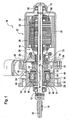
- the Actuator 10 has one at the free end Actuating shaft 12 has a pinion 14, via which a Not shown differential lock of a vehicle can be operated.
- the Actuator a drive unit 16 and electromagnetic brake unit 18, the Drive unit 16 and the brake unit 18 in one common housing 20 is housed.
- the housing 20 comprises a cup-shaped base housing 22, which the Drive unit 16 receives.
- the housing 20 further comprises a housing cover 24 in which the brake unit 18th is housed. By means of connecting screws 26 Housing cover 24 tightly screwed to the base housing 20 become.
- the drive unit 16 comprises permanent magnets on the housing side 28, the one on the actuating shaft 12 rotatably arranged anchor package 30 cooperate. Also includes the drive unit 16 one on the operating shaft non-rotatably arranged commutator 32 against which The outer surface of brushes 36 mounted in quivers 34 act.
- the Quiver 34 are in this case perpendicular to the longitudinal axis 38 the actuating shaft 12 arranged brush support plate 40 attached.
- On the brush support plate 40 are also various electrical components, for example suppressors, intended.
- the brake unit 18 includes a non-rotatable on the Actuating shaft 12 arranged brake hub flange 42 and one against the housing cover 24 secured against rotation, one Brake winding 44 comprising brake body 46. Also includes the brake unit 18 opposite the actuating shaft 12 rotatably arranged, axially movable brake disc 48, which is designed as a brake disc ring. at Energizing the brake winding 44 acts on the brake disc 48 against the likewise annular brake body 46. Consequently, when the brake winding 46 is energized, the Braking effect and the actuating shaft 12 is on the Brake hub flange 42, the brake disc 48 and the Brake body 46 against the housing 20 or against the Housing cover 24 secured against rotation.
- the brake body 46 in the housing cover 24 sees the Brake body 46 extending coaxially to the longitudinal axis 38 Pin 50 in front, which in appropriately trained, projecting blind holes 52 on the housing cover side.
- the brake body 46 within the housing cover 24 are caulking sections 54 on the housing cover 24 provided that in corresponding sections on the Shell surface of the brake body 46 are caulked.
- a spring element 58 provided that the brake disc 48 against the Brake disc support section 56 acted upon.
- notches 66 and 68 are provided along a line.
- the Notch 66 is in the area of the brake hub flange 42 and the notch 68 in the area of the drive unit 16.
- the actuating shaft 12 has a total of four notches 66 and four notches 68 each.
- the notches 66, 68 are each offset by 90 °.
- the notches as such, each have a notch angle of 90 °.
- the height h of the notches is in the range of about 2/100 mm.
- the Actuating shaft 12 no notches. These areas can be ground to achieve high accuracy his. After the grinding process, the notches 66, 68 in the actuating shaft are introduced.
- the notches have 66, 68 each have conical sections 70 at their endings, which extend in the axial direction over the length 1.
- the inside of the brake hub flange 42 has one on the actuating shaft 12 tapered section 72 on. Due to the conical sections 70 and conical section 72 takes place when joining the Brake hub flange 42 with the actuating shaft 12 a Self-centering. When joining the bumps dig Notches 66, 68 in the inside of the preferably from Aluminum trained brake hub flange 42 a. Between the brake hub flange 42 and the actuating shaft 12 consequently a notch press connection that with relative low press-in forces can be realized.
- the notches 68 act in the assembled state as in Figure 1 is shown with the anchor package 30 and with the Commutator 32 together. Because of the conical sections 70 the notches 68 also occur here when joining Self-centering. Because advantageously the form-fitting Firm fit between the actuating shaft 12 and the commutator 32 or the anchor package 30 only in the increases of Notches 68 occurs, the press-in forces can be relative be kept low.
- the ground section of the Actuating shaft 12, which in the installed state with the Bearing element 62 cooperates when joining the Actuating shaft 12 with commutator 32 and armature package 30 not affected.
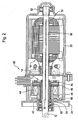
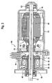
- FIG. 2 shows a second one according to the invention Actuating device 80 and a third in FIG Actuating device 90 according to the invention shown.
- the the actuating device 10 are corresponding components with the actuators 80 and 90 with the same Provide reference numbers.
- the actuator 80 differs from that Actuator 10 and others in that the brake unit-side bearing element 82 directly on the actuating shaft 12 arranged bearing section having. Furthermore, the brake body 46 is not arranged on the housing cover side, but is via a Plain bearing 84 arranged on the brake hub flange 42. to Anti-rotation of the brake body 46 is a according to Figure 2 in a toothing arranged on the housing cover side engaging nose 86 provided.
- the embodiment according to FIG. 2 has the advantage that the between the brake body 46 and the brake disc 48 Air gap to be provided in the brake body 46 and the Brake disc 48 having fixed assembly can be.
- FIG. 1 Another difference between the actuator 10 according to FIG. 1 and the actuating device 80 according to Figure 2 is that in the actuator 80 none two notches 66 and 68 arranged along a line are provided. Rather, they are about Drive unit 16 and the braking unit 18 extending Notches 88 are provided. The notches 88 'are corresponding Figures 4 and 5 formed. Because no Interruptions in the notches 88 are provided, these are easier to manufacture.
- the actuator 90 differs from the actuator 80 in that the brake disc carrier 56 separately from the Brake hub flange 42 is formed as a separate component.
- the brake disc carrier 56 is here a Brake disc hub 57 arranged on the actuating shaft 12.
- the Air gap between the brake disc 48 and the brake body 46 still during the assembly of the brake hub flange 42 or of the brake disc support portion 56 can be adjusted.
Landscapes
- Physics & Mathematics (AREA)
- Electromagnetism (AREA)
- Engineering & Computer Science (AREA)
- Power Engineering (AREA)
- Braking Arrangements (AREA)
- Retarders (AREA)
Abstract
Description
Die Erfindung betrifft eine Betätigungsvorrichtung, insbesondere zur Betätigung von Sperrdifferentialen von Fahrzeugen.The invention relates to an actuating device, in particular for the actuation of limited slip differentials Vehicles.
Derartige Betätigungsvorrichtungen finden insbesondere im Kraftfahrzeug zur Unterstützung der Antriebs- und Bremssysteme Verwendung. Sie umfassen regelmäßig eine Antriebseinheit zum Antreiben einer Betätigungswelle und eine Abbremseinheit zum Abbremsen der Betätigungswelle. Über die Betätigungswelle kann ein Sperrdifferential zu- bzw. abgeschaltet werden. Den eigentlichen Schaltvorgang übernimmt hierbei die Antriebseinheit. Die Bremseinheit hält die Betätigungswelle in einer vorgegebenen Stellung.Such actuators are particularly in the Motor vehicle to support the drive and Brake systems use. They regularly include one Drive unit for driving an actuating shaft and a braking unit for braking the actuating shaft. about the actuating shaft can lock or lock a differential be switched off. The actual switching process takes over the drive unit. The brake unit stops the actuating shaft in a predetermined position.
An derartige Betätigungsvorrichtungen sind hohe Anforderungen zu stellen. Insbesondere müssen die Betriebstemperaturen bis 200° C standhalten. Die Betätigungswelle darf ferner nur einem relativ geringen Spiel unterliegen, um ein funktionssicheres Betätigen der Sperrdifferentiale gewährleisten zu können. Außerdem soll die Betätigungsvorrichtung einen einfachen Aufbau aufweisen und auf einfache Art und Weise montierbar sein. Die Betätigungsvorrichtung soll zudem kompakt bauen.Such actuators are high To make demands. In particular, the Withstand operating temperatures up to 200 ° C. The Actuating shaft may also only be a relatively small one Subject to safe operation of the game To be able to guarantee limited slip differentials. In addition, should the actuator has a simple structure and be easy to assemble. The Actuator should also be compact.
Der vorliegenden Erfindung liegt deshalb die Aufgabe zugrunde, eine Betätigungsvorrichtung vorzuschlagen, die den genannten Anforderungen gerecht wird.The present invention is therefore based on the object to propose an actuator that the mentioned requirements.
Zur Lösung der Aufgabe ist eine Betätigungsvorrichtung vorgesehen, mit einer Betätigungswelle, mit einer Antriebseinheit zum Antreiben der Betätigungswelle, wobei die Antriebseinheit ein auf der Betätigungswelle drehfest angeordnetes Ankerpaket sowie einen auf der Betätigungswelle drehfest angeordneten Kommutator aufweist, mit einer elektromagnetischen Bremseinheit zum Abbremsen der und/oder Halten der Betätigungswelle, wobei die Bremseinheit einen auf der Ankerwelle drehfest angeordneten Bremsnabenflansch umfasst, und mit einem die Antriebseinheit und die Bremseinheit dicht umschließenden, ein- oder mehrteilig ausgebildeten Gehäuse, wobei das freie Ende der Betätigungswelle aus dem Gehäuse herausragt.To solve the problem is an actuator provided, with an actuating shaft, with a Drive unit for driving the actuating shaft, wherein the drive unit is rotatably on the actuating shaft arranged anchor package and one on the actuating shaft rotatably arranged commutator, with a electromagnetic brake unit for braking the and / or Holding the actuating shaft, the brake unit one brake hub flange arranged on the armature shaft in a rotationally fixed manner comprises, and with a the drive unit and Brake unit tightly enclosing, one or more parts trained housing, the free end of the Actuating shaft protrudes from the housing.
Eine derartige Betätigungsvorrichtung hat den Vorteil, dass die Antriebseinheit und die Bremseinheit räumlich dicht beieinander liegen und von einem gemeinsamen, ggf. mehrteilig ausgebildeten, Gehäuse umschlossen werden. Die Betätigungsvorrichtung baut folglich sehr kompakt und ist sicher gegen Umwelteinflüsse geschützt.Such an actuator has the advantage that the drive unit and the brake unit are spatially sealed lie together and by a common, if necessary multi-part housing are enclosed. The Actuator is therefore very compact and is protected against environmental influences.
Eine bevorzugte Ausführungsform der Erfindung sieht vor, dass die Wellenoberfläche der Betätigungswelle axial verlaufende Kerbungen aufweist, die mit der Innenseite des Bremsnabenflansches eine Kerbpressverbindung bilden. Das Fügen mittels Kerben hat den Vorteil, dass es eine sehr einfache und formschlüssige Verbindung bildet, bei der die Fügepartner mit nicht zu engen, und damit teuren, Durchmessertoleranzen gefertigt werden müssen. Bei der Kerbpressverbindung werden die Fügepartner vorteilhafterweise lediglich im Bereich der Kerbungen formschlüssig gefügt. Dadurch sind die auftretenden Einpresskräfte, im Vergleich zu toleranzgenau zu fertigenden, über den gesamten Umfang der Fügeteile wirkenden Pressverbindungen, sehr viel geringer. Insbesondere dünnere Betätigungswellen können mit dem Bremsnabenflansch gefügt werden, ohne dass die Gefahr einer unerwünschten Verformung der Welle besteht. Schon eine geringe Verformung der Welle führt zu einem Taumelschlag und macht sich vor allem als störendes Geräusch beim Betrieb der Betätigungsvorrichtung bemerkbar.A preferred embodiment of the invention provides that the shaft surface of the actuation shaft is axial has running notches that match the inside of the Brake hub flange form a notch press connection. The Joining by means of notches has the advantage that it is a very simple and positive connection, in which the Joining partners with not too tight, and therefore expensive, Diameter tolerances have to be manufactured. In the Notch press connection become the joining partners advantageously only in the area of the notches form-fitting. This makes them appear Press-in forces compared to tolerances manufacturing, over the entire circumference of the parts to be joined acting press connections, much less. In particular, thinner actuation shafts can be used with the Brake hub flange can be joined without the risk of a undesirable deformation of the shaft. Already a slight deformation of the shaft leads to a wobble and makes itself especially as a disturbing noise when operating the Actuator noticeable.
Beim Fügen der Welle mit dem Fügepartner graben sich die Kerbungen vorteilhafterweise form- und kraftschlüssig in die Innenseite des Bremsnabenflansches ein. Die Innenseite des Bremsnabenflansches muss hierfür keine besonderen Anforderungen genügen und muss auch sonst nicht speziell bearbeitet werden.When joining the shaft with the joining partner, they dig themselves Notches advantageously positive and non-positive in the Inside of the brake hub flange. The inside of the Brake hub flange does not have to be special Requirements meet and need not be special to be edited.
Es hat sich als vorteilhaft herausgestellt, wenn die Höhe der Kerbungen im Bereich von etwa 2/100 mm liegen. Bei derartigen Kerbungen wird bei relativ geringen Fügekräften eine ausreichend gute Verbindung der Fügepartner erreicht.It has proven to be beneficial if the height the notches are in the range of about 2/100 mm. at notches of this type are used at relatively low joining forces a sufficiently good connection between the joining partners is achieved.
Vorteilhafterweise ist der Bremsnabenflansch aus Aluminium gebildet. Gerade bei Verwendung eines derartig weichen Materials findet ein vorteilhaftes, relativ geringe Einpresskräfte erforderndes Eingraben der Kerbungen in das Aluminium statt. Da die Welle aus härterem Material als Aluminium gebildet ist, kann zudem eine unerwünschte Verformung der Welle beim Fügen der Welle mit dem Bremsnabenflansch nicht erfolgen.The brake hub flange is advantageously made of aluminum educated. Especially when using such a soft Materials finds an advantageous, relatively low Press-in forces require the notches to be buried in the Aluminum instead. Because the shaft is made of harder material than Aluminum is formed can also be an undesirable Deformation of the shaft when joining the shaft with the Brake hub flange not done.
Bei einer weiteren, besonders bevorzugten Ausführungsform der Erfindung ist vorgesehen, dass die Kerbungen jeweils an wenigstens einem Ende einen konischen Anstiegbereich aufweisen. Das Vorsehen eines derartigen konischen Anstiegbereichs hat den Vorteil, dass beim Fügen der Fügepartner ein Vorzentrieren erfolgt, bevor die maximale Fügekraft, aufgrund der Höhe der Kerbungen, zum Tragen kommt. Ferner kann es nicht zum Verkanten der Fügeteile kommen, und die Gefahr von Fressern durch evtl. vor den Fügeteilen vorhergeschobenen Spänen entfällt.In a further, particularly preferred embodiment the invention provides that the notches each at least one end has a conical rise area exhibit. The provision of such a conical Rising area has the advantage that when joining the Pre-centering is done before the maximum Joining force, due to the height of the notches, to bear comes. Furthermore, it cannot tilt the parts to be joined come, and the danger of eater through possibly before There is no need to join chips that have been pushed in.
Eine vorteilhafte Ausgestaltung der Erfindung ergibt sich dann, wenn die Kerbungen nur in Bereichen der Betätigungswelle angeordnet sind, in denen der Bremsnabenflansch hohen radial wirkenden Kräften ausgesetzt ist. Dies hat den Vorteil, dass die Kerbungen nicht über die gesamte Länge der Betätigungswelle auszubilden sind. Außerdem werden die Fügekräfte hierdurch vermindert.An advantageous embodiment of the invention results then if the notches only in areas of the Actuating shaft are arranged in which the Brake hub flange exposed to high radial forces is. This has the advantage that the notches do not have the entire length of the actuating shaft are to be formed. This also reduces the joining forces.
Die Kerbungen können sich vorteilhafterweise durchlaufend und/oder mit Unterbrechungen über die gesamte Länge der Betätigungswelle erstrecken. Dabei bildet die der Betätigungswelle zugewandte Innenseite des Kommutators und/oder des Ankerpakets, neben dem Bremsnabenflansch, ebenfalls eine Kerbpressverbindung. Die in Zusammenhang mit dem Bremsnabenflansch sich ergebenden Vorteile gelten entsprechend für die Kerbpressverbindung der Betätigungswelle mit dem Kommutator und/oder mit dem Ankerpaket.The notches can advantageously run continuously and / or intermittently along the entire length of the Extend actuator shaft. The forms the Actuating shaft facing the inside of the commutator and / or the anchor package, next to the brake hub flange, also a notch press connection. The related the resulting advantages apply to the brake hub flange accordingly for the notched press connection Actuating shaft with the commutator and / or with the Anchor package.
Erfindungsgemäß kann ferner vorgesehen sein, dass die Betätigungswelle abschnittsweise geschliffen ist, wobei das Schleifen insbesondere vor der Anbringung der Kerbungen erfolgt. Dies hat den Vorteil, dass geschliffene Bereiche, insbesondere zur Anbringung von Lagerelementen, vorgesehen sein können. Beim Fügen der Betätigungswelle mit dem Fügepartner werden die geschliffenen Bereiche nicht beeinträchtigt, da der Durchmesser der Betätigungswelle im Bereich der Kerbungen größer ist, als im Bereich der geschliffenen Teile. Folglich können die Lagerelemente mit den geschliffenen Abschnitten der Betätigungswelle nach dem Fügen der Betätigungswelle mit dem Bremsnabenflansch, dem Kommutator und/oder dem Ankerpaket gefügt werden. Um einen sehr genauen Kerbdurchmesser herstellen zu können, kann erfindungsgemaß ebenfalls vorgesehen sein, dass die Betätigungswelle vor dem Fügen mit dem Fügepartner bzw. den Fügepartnern komplett geschliffen wird.According to the invention it can further be provided that the Actuating shaft is ground in sections, the Sanding especially before making the notches he follows. This has the advantage that ground areas, in particular for attaching bearing elements could be. When joining the actuating shaft with the The ground areas do not become joining partners impaired because the diameter of the actuating shaft in Area of the notches is larger than in the area of ground parts. Consequently, the bearing elements can the ground sections of the actuating shaft after Join the actuating shaft with the brake hub flange, the Commutator and / or the armature package are added. To one to be able to produce very precise notch diameters According to the invention also be provided that the Actuating shaft before joining with the joining partner or Joining partners is completely sanded.
Bei einer weiteren Ausführungsform der Erfindung ist zur Montage der Bremseinheit die Bremseinheit über das freie Ende der Betätigungswelle auf die Betätigungswelle axial aufschiebbar. Während des Aufschiebens graben sich die Kerbungen in den Bremsflansch der Bremseinheit ein. Eine derartige Montage hat den Vorteil, dass sie blind erfolgen kann.In a further embodiment of the invention Mounting the brake unit the brake unit over the free End of the actuating shaft on the actuating shaft axially pushed. During the postponement they dig themselves Notches in the brake flange of the brake unit. A Such assembly has the advantage that it is done blind can.
Ferner ist denkbar, dass die Innenseite des Bremsnabenflansches einen konisch auf die Betätigungswelle zulaufenden Abschnitt aufweist. Ein derartiger Abschnitt des Bremsnabenflansches trägt zur Selbstzentrierung der Fügepartner beim Fügen bei.It is also conceivable that the inside of the Brake hub flange a conical on the actuating shaft has tapered section. Such a section of the Brake hub flange contributes to the self-centering of the Joining partner when joining.
Bei einer besonders bevorzugten Ausführungsform der Erfindung sind vier um 90° versetzt zueinander angeordnete Kerbungen auf der Betätigungswelle vorgesehen. Hierdurch wird neben dem axialen Festsitz auch eine ausreichende Verdrehsicherung der Fügepartner zueinander gewährleistet.In a particularly preferred embodiment of the Invention are four arranged at 90 ° to each other Notches are provided on the actuating shaft. hereby in addition to the axial tight fit also a sufficient Secured against rotation of the joining partners to each other.
Um ein sicheres Führen der Betätigungswelle auch während des Abbremsvorganges durch die Bremseinheit gewährleisten zu können, ist erfindungsgemäß bei einer bevorzugten Ausführungsform der Erfindung vorgesehen, dass sich die Betätigungswelle im Bereich der Bremseinheit über wenigstens ein Lagerelement gegen das Gehäuse abstützt.In order to safely guide the actuating shaft even during the Decelerate the braking unit to ensure can, according to the invention is a preferred Embodiment of the invention provided that the Actuating shaft in the area of the brake unit via at least supports a bearing element against the housing.
Vorteilhafterweise ist der wellenseitige Lagerabschnitt des Lagerelements unmittelbar auf der Betätigungswelle angeordnet. Dies hat den Vorteil, dass der Kraftfluss direkt von der Betätigungswelle über das Lagerelement in das Gehäuse geleitet wird.The shaft-side bearing section of the Bearing element directly on the actuating shaft arranged. This has the advantage that the power flow is direct from the actuating shaft via the bearing element into the Housing is headed.
Alternativ hierzu ist denkbar, dass der wellenseitige Lagerabschnitt des Lagerelements auf dem Bremsnabenflansch angeordnet ist. Dies hat den Vorteil, dass der Bremsnabenflansch samt Lagerelement als selbstständig handhabbare Baugruppe vormontiert werden kann. Der Bremsnabenflansch samt Lagerelement wird dann gemeinsam über den Bremsnabenflansch mit der Betätigungswelle gefügt.Alternatively, it is conceivable that the shaft side Bearing section of the bearing element on the brake hub flange is arranged. This has the advantage that the Brake hub flange and bearing element as independent manageable assembly can be pre-assembled. The Brake hub flange together with the bearing element is then jointly over the brake hub flange with the actuating shaft.
Bei einer weiteren Ausführungsform der Erfindung ist vorgesehen, dass die Bremseinheit einen gegen das Gehäuse drehgesicherten, eine Bremswicklung umfassenden Bremskörper und einen eine Bremsscheibe aufweisenden, mit der Betäti-gungswelle drehfest verbundenen Bremsscheibenträger aufweist, wobei bei Bestromung der Bremswicklung die Bremsscheibe gegen den Bremskörper gezogen oder von dem Bremskörper abgestoßen wird. Hierdurch wird über eine geringe Anzahl von Bauteilen eine Bremseinheit verwirklicht, die den Anforderungen an die Betätigungsvorrichtung gerecht wird. Die Bremsscheibe ist vorzugsweise als Bremsscheibenring ausgebildet, wobei in montiertem Zustand die Betätigungswelle den zentralen Durchbruch des Bremsscheibenringes durchgreift.In another embodiment of the invention provided that the brake unit one against the housing Non-rotating brake body comprising a brake winding and a brake disc with which Actuating shaft rotatably connected brake disc carrier has, with the energization of the brake winding Brake disc pulled against or from the brake body Brake body is repelled. This will have a small number of components realizes a braking unit, that meet the requirements for the actuator becomes. The brake disc is preferably as Brake disc ring designed, in the assembled state the actuation shaft the central breakthrough of the Reaches through the brake disc ring.
Vorteilhafterweise ist der Bremskörper als Magnetbremskörper ausgebildet. Dies hat den Vorteil, dass keine zusätzlichen Dauermagneten vorzusehen sind, die im Zusammenspiel mit der Bremswicklung eine geeignete Bremswirkung erzielen.The brake body is advantageously a magnetic brake body educated. This has the advantage that no additional Permanent magnets are to be provided, which in interaction with the Achieve a suitable braking effect.
Bei einer besonders bevorzugten Ausführungsform der Erfindung ist vorgesehen, dass die Bremsscheibe gegenüber dem Bremsscheibenträger axial bewegbar ist, wobei zwischen der Bremsscheibe und dem Bremsscheibenträger ein Federelement angeordnet ist, das die Bremsscheibe in die dem Bremskörper zugewandter oder abgewandter Richtung beaufschlagt. Dies hat den Vorteil, dass sich die Bremsscheibe sowohl bei betätigter als auch bei nicht betätigter Bremseinheit in einer definierten Position befindet. Dadurch werden Klappergeräusche bei Betrieb der Betätigungsvorrichtung unterbunden.In a particularly preferred embodiment of the Invention is provided that the brake disc opposite the brake disc carrier is axially movable, wherein between the brake disc and the brake disc carrier Spring element is arranged that the brake disc in the Brake body facing or facing direction applied. This has the advantage that the Brake disc both when activated and not actuated brake unit in a defined position located. This will make rattling noises when the Actuator prevented.
Der Bremsscheibenträger kann unmittelbar oder mittels einer Bremsscheibennabe auf der Betätigungswelle angeordnet sein. Der Bremsscheibenträger oder die Bremsscheibennabe ist hierbei als separates Bauteil, oder einstückig mit dem Bremsnabenflansch ausgebildet. Die einstückige Ausbildung mit dem Bremsnabenflansch hat den Vorteil, dass zusätzliche Bauteile entfallen. Lagetoleranzen können hierdurch geringer gehalten werden.The brake disc carrier can be used directly or by means of a Brake disc hub can be arranged on the actuating shaft. The brake disc carrier or the brake disc hub is here as a separate component, or in one piece with the Brake hub flange designed. The one-piece training with the brake hub flange has the advantage that additional Components are eliminated. As a result, position tolerances can be reduced being held.
Eine weitere Ausführungsform der Erfindung zeichnet sich dadurch aus, dass der Bremskörper bremsnabenflanschseitig befestigt ist, wobei zwischen dem Bremskörper und dem Bremsnabenflansch ein Lager, insbesondere ein Gleitlager, angeordnet ist. Dies hat den Vorteil, dass der Bremskörper mit dem Bremsnabenflansch als selbstständig handhabbare Baugruppe ausgebildet sein kann.Another embodiment of the invention stands out characterized in that the brake body on the brake hub flange side is attached, between the brake body and the Brake hub flange a bearing, in particular a plain bearing, is arranged. This has the advantage that the brake body with the brake hub flange as independently manageable Assembly can be formed.
Andererseits ist erfindungsgemäß ebenfalls denkbar, dass der Bremskörper gehäuseseitig befestigt ist. Bei einer derartigen Ausführungsform der Erfindung findet sich in montiertem Zustand vorteilhafterweise zwischen dem Bremskörper und dem Bremsnabenflansch oder der Betätigungswelle ein Luftspalt. Dies hat den Vorteil, dass ein Lagerelement, insbesondere ein Gleitlager, zwischen dem Bremskörper und dem Bremsnabenflansch oder der Betätigungswelle nicht vorzusehen ist.On the other hand, it is also conceivable according to the invention that the Brake body is attached to the housing. At a Such embodiment of the invention can be found in assembled state advantageously between the Brake body and the brake hub flange or the Actuating shaft an air gap. This has the advantage that a bearing element, in particular a plain bearing, between the Brake body and the brake hub flange or the Actuating shaft is not to be provided.
Zur Realisierung einer Verdrehsicherung des Bremskörpers gegen das Gehäuse kann der Bremskörper mit dem Gehäuse beispielsweise abschnittsweise verstemmt sein. Ferner ist denkbar, dass der Bremskörper definierte Erhebungen aufweist, beispielsweise in Form von Zapfen, die in damit korrespondierende Aussparungen, beispielsweise Sackbohrungen, eingreifen.To implement an anti-rotation device for the brake body against the housing, the brake body with the housing be caulked in sections, for example. Furthermore is conceivable that the brake body defined elevations has, for example in the form of pegs in it corresponding recesses, for example Blind holes, intervene.
Vorteilhafterweise weist das Gehäuse ein topfförmiges Grundgehäuse und einen Gehäusedeckel mit einem Durchbruch für die Betätigungswelle auf. Die Antriebseinheit kann hierbei im Bereich des Grundgehäuses und die Bremseinheit im Bereich des Gehäusedeckels angeordnet sein.The housing advantageously has a cup-shaped one Basic housing and a housing cover with an opening for the actuating shaft. The drive unit can here in the area of the basic housing and the brake unit in Area of the housing cover can be arranged.
Weitere vorteilhafte Ausgestaltungen und Einzelheiten der Erfindung sind der folgenden Beschreibung zu entnehmen, in der die Erfindung anhand der in der Zeichnung dargestellten Ausführungsbeispiele näher beschrieben und erläutert ist.Further advantageous refinements and details of Invention can be found in the following description, in of the invention with reference to that shown in the drawing Exemplary embodiments are described and explained in more detail.
Es zeigen:
- Figur 1
- einen Längsschnitt durch eine erste erfindungsgemäße Betätigungsvorrichtung,
- Figur 2
- einen Längsschnitt durch eine zweite erfindungsgemäße Betätigungsvorrichtung,
- Figur 3
- einen Längsschnitt durch eine dritte erfindungsgemäße Betätigungsvorrichtung,
- Figur 4
- einen Querschnitt durch eine Betätigungswelle einer erfindungsgemäßen Betätigungsvorrichtung, und
- Figur 5
- eine Seitenansicht einer Betätigungswelle einer erfindungsgemäßen Betätigungsvorrichtung.
- Figure 1
- 2 shows a longitudinal section through a first actuating device according to the invention,
- Figure 2
- 2 shows a longitudinal section through a second actuating device according to the invention,
- Figure 3
- 2 shows a longitudinal section through a third actuating device according to the invention,
- Figure 4
- a cross section through an actuating shaft of an actuating device according to the invention, and
- Figure 5
- a side view of an actuating shaft of an actuating device according to the invention.
In der Figur 1 ist eine erste Ausführungsform einer
erfindungsgemäßen Betätigungseinrichtung 10 dargestellt. Die
Betätigungseinrichtung 10 weist an dem freien Ende einer
Betätigungswelle 12 ein Ritzel 14 auf, über welches ein
nicht dargestelltes Sperrdifferential eines Fahrzeuges
betätigt werden kann. Dabei umfasst die
Betätigungseinrichtung eine Antriebseinheit 16 und eine
elektromagnetische Bremseinheit 18, wobei die
Antriebseinheit 16 und die Bremseinheit 18 in einem
gemeinsamen Gehäuse 20 untergebracht ist. Das Gehäuse 20
umfasst ein topfförmiges Grundgehäuse 22, welches die
Antriebseinheit 16 aufnimmt. Ferner umfasst das Gehäuse 20
einen Gehäusedeckel 24, in dem die Bremseinheit 18
untergebracht ist. Mittels Verbindungsschrauben 26 kann der
Gehäusedeckel 24 mit dem Grundgehäuse 20 dicht verschraubt
werden.1 shows a first embodiment of a
Die Antriebseinheit 16 umfasst gehäuseseitige Dauermagnete
28, die mit einem auf der Betätigungswelle 12 drehfest
angeordnetem Ankerpaket 30 zusammenwirken. Ferner umfasst
die Antriebseinheit 16 einen auf der Betätigungswelle
drehfest angeordneten Kommutator 32, gegen dessen
Mantelfläche in Köchern 34 gelagerte Bürsten 36 wirken. Die
Köcher 34 sind hierbei auf einer senkrecht zur Längsachse 38
der Betätigungswelle 12 angeordneten Bürstentrageplatte 40
befestigt. Auf der Bürstentrageplatte 40 sind ferner
verschiedene elektrische Bauteile, beispielsweise Entstörer,
vorgesehen.The
Die Bremseinheit 18 umfasst einen drehfest auf der
Betätigungswelle 12 angeordneten Bremsnabenflansch 42 sowie
einen gegen den Gehäusedeckel 24 drehgesicherten, eine
Bremswicklung 44 umfassenden Bremskörper 46. Ferner umfasst
die Bremseinheit 18 eine gegenüber der Betätigungswelle 12
drehfest angeordnete, bedingt axial bewegbare Bremsscheibe
48, die als Bremsscheibenring ausgebildet ist. Bei
Bestromung der Bremswicklung 44 wirkt die Bremsscheibe 48
gegen den ebenfalls ringförmig ausgebildeten Bremskörper 46.
Bei Bestromung der Bremswicklung 46 tritt folglich der
Bremseffekt ein und die Betätigungswelle 12 wird über den
Bremsnabenflansch 42, die Bremsscheibe 48 und den
Bremskörper 46 gegen das Gehäuse 20 bzw. gegen den
Gehäusedeckel 24 drehgesichert. Zur drehsicheren Anordnung
des Bremskörpers 46 in dem Gehäusedeckel 24 sieht der
Bremskörper 46 sich koaxial zur Längsachse 38 erstreckende
Zapfen 50 vor, die in entsprechend ausgebildete,
gehäusedeckelseitige Sackbohrungen 52 ragen. Zur sicheren
Halterung des Bremskörpers 46 innerhalb des Gehäusedeckels
24 sind Verstemmabschnitte 54 am Gehäusedeckel 24
vorgesehen, die in entsprechende Abschnitte an der
Mantelfläche des Bremskörpers 46 verstemmt werden.The
Um bei nicht betätigter Bremseinheit 18 eine definierte
Position der Bremsscheibe 48 zu gewährleisten, ist zwischen
der Bremsscheibe 48 und einem Bremsscheibenträgerabschnitt
56 des Bremsnabenflansches 42 ein Federelement 58
vorgesehen, dass die Bremsscheibe 48 gegen den
Bremsscheibenträgerabschnitt 56 beaufschlagt.To a defined when the
Zur Lagerung der Betätigungswelle 12 sind zwei Lagerelemente
60 und 62 vorgesehen.There are two bearing elements for mounting the actuating
Bei der Betätigungseinrichtung 10 gemäß Figur 1 ist der
wellenseitige Lagerabschnitt des Lagerelements 60 auf dem
Bremsnabenflansch 42 angeordnet. Dies hat den Vorteil, dass
eine einfache Montage der Betätigungseinrichtung 10 möglich
ist, da die gesamte Bremseinheit 18 samt Lagerelement 60 in
den Gehäusedeckel 24 eingepresst bzw. eingesetzt werden
kann. Die gesamte Bremseinheit 18 samt Lagerelement 62 kann
folglich als zusammenhängende Baugruppe separat vormontiert
und gehandhabt werden. Zwischen der innenliegenden
Mantelfläche des Bremskörpers 46 und der dieser Mantelfläche
zugewandten Seite des Bremsnabenflansches 42 ist ein
Luftspalt 64 vorgesehen. Lagerelemente oder Lagermittel
zwischen dem Bremskörper 46 und dem Bremsnabenflansch 42
sind folglich nicht erforderlich.In the
In dem Schnitt gemäß Figur 1 sind an der Betätigungswelle 12
entlang einer Linie zwei Kerbungen 66 und 68 vorgesehen. Die
Kerbung 66 liegt im Bereich des Bremsnabenflansches 42 und
die Kerbung 68 im Bereich der Antriebseinheit 16.In the section according to FIG. 1, there are 12 on the actuating shaft
two
Wie dem Querschnitt gemäß Figur 4 entnommen werden kann,
weist die Betätigungswelle 12 insgesamt je vier Kerbungen 66
und je vier Kerbungen 68 auf. Die Kerbungen 66, 68 sind
jeweils um 90° versetzt zueinander angeordnet. Die Kerbungen
als solche weisen einen Einkerbwinkel von jeweils 90° auf.
Die Höhe h der Kerbungen liegt im Bereich von etwa 2/100 mm.
Im Bereich der Lagerelemente 60 und 62 weist die
Betätigungswelle 12 keine Kerbungen auf. Diese Bereiche
können zur Realisierung einer hohen Genauigkeit geschliffen
sein. Nach dem Schleifvorgang können die Kerbungen 66, 68 in
die Betätigungswelle eingebracht werden.As can be seen from the cross section according to FIG. 4,
the actuating
Wie der Figur 5 entnommen werden kann, weisen die Kerbungen
66, 68 an ihren Endungen jeweils konische Abschnitte 70 auf,
die sich in axialer Richtung über die Länge 1 erstrecken.As can be seen from FIG. 5, the notches have
66, 68 each have
Zur Montage der Betätigungswelle 12 mit dem
Bremsnabenflansch 42 wird das das Ritzel 14 aufweisende Ende
der Betätigungswelle, ohne Ritzel 14, in den zentralen
Durchbruch des Bremsnabenflansches eingeführt. Die
Innenseite des Bremsnabenflansches 42 weist hierbei einen
auf die Betätigungswelle 12 zulaufenden konischen Abschnitt
72 auf. Aufgrund der konischen Abschnitte 70 und des
konischen Abschnitts 72 erfolgt beim Fügen des
Bremsnabenflansches 42 mit der Betätigungswelle 12 eine
Selbstzentrierung. Beim Fügen graben sich die Erhöhungen der
Kerbungen 66, 68 in die Innenseite des vorzugsweise aus
Aluminium ausgebildeten Bremsnabenflansches 42 ein. Zwischen
dem Bremsnabenflansch 42 und der Betätigungswelle 12 bildet
sich folglich eine Kerbpressverbindung, die mit relativ
geringen Einpresskräften realisiert werden kann.To assemble the
Die Kerbungen 68 wirken im montierten Zustand, wie er in
Figur 1 dargestellt ist, mit dem Ankerpaket 30 sowie mit dem
Kommutator 32 zusammen. Aufgrund der konischen Abschnitte 70
der Kerbungen 68 erfolgt auch hier beim Fügen eine
Selbstzentrierung. Da vorteilhafterweise der formschlüssige
Festsitz zwischen Betätigungswelle 12 und dem Kommutator 32
bzw. dem Ankerpaket 30 lediglich in den Erhöhungen der
Kerbungen 68 erfolgt, können die Einpresskräfte relativ
gering gehalten werden. Der geschliffene Abschnitt der
Betätigungswelle 12, der im eingebauten Zustand mit dem
Lagerelement 62 zusammenwirkt, wird beim Fügen der
Betätigungswelle 12 mit Kommutator 32 und Ankerpaket 30
nicht beeinträchtigt.The
In der Figur 2 ist eine zweite erfindungsgemäße
Betätigungseinrichtung 80 und in der Figur 3 eine dritte
erfindungsgemäße Betätigungseinrichtung 90 dargestellt. Der
der Betätigungseinrichtung 10 entsprechende Bauteile sind
bei den Betätigungseinrichtungen 80 und 90 mit den gleichen
Bezugszahlen versehen.FIG. 2 shows a second one according to the
Die Betätigungseinrichtung 80 unterscheidet sich von der
Betätigungseinrichtung 10 u.a. dadurch, dass das
bremseinheitsseitige Lagerelement 82 einen unmittelbar an
der Betätigungswelle 12 angeordneten Lagerabschnitt
aufweist. Ferner ist der Bremskörper 46 nicht
gehäusedeckelseitig angeordnet, sondern ist über ein
Gleitlager 84 an dem Bremsnabenflansch 42 angeordnet. Zur
Verdrehsicherung des Bremskörpers 46 ist gemäß Figur 2 eine
in eine gehäusedeckelseitig angeordnete Verzahnung
eingreifende Nase 86 vorgesehen.The
Die Ausführungsform gemäß Figur 2 hat den Vorteil, dass der
zwischen dem Bremskörper 46 und der Bremsscheibe 48
vorzusehende Luftspalt in der den Bremskörper 46 und die
Bremsscheibe 48 aufweisenden Baugruppe fest eingestellt
werden kann.The embodiment according to FIG. 2 has the advantage that the
between the
Ein weiterer Unterschied zwischen der Betätigungseinrichtung
10 gemäß Figur 1 und der Betätigungseinrichtung 80 gemäß
Figur 2 ist, dass bei der Betätigungseinrichtung 80 keine
zwei entlang einer Linie angeordnete Kerbungen 66 und 68
vorgesehen sind. Es sind vielmehr sich über die
Antriebseinheit 16 und die Bremseinheit 18 erstreckende
Kerbungen 88 vorgesehen. Die Kerbungen 88'sind entsprechend
den Figuren 4 und 5 ausgebildet. Dadurch, dass keine
Unterbrechungen der Kerbungen 88 vorgesehen sind, sind diese
einfacher zu fertigen.Another difference between the actuator
10 according to FIG. 1 and the
Bei der Betätigungseinrichtung 90 gemäß Figur 3 ist
entsprechend der Betätigungsvorrichtung 80 nach Figur 2 das
Lagerelement 82 unmittelbar an der Betätigungswelle 12
anliegend angeordnet. Die Betätigungseinrichtung 90
unterscheidet sich von der Betätigungseinrichtung 80
dadurch, dass der Bremsscheibenträger 56 separat von dem
Bremsnabenflansch 42 als eigenes Bauteil ausgebildet ist.
Der Bremsscheibenträger 56 ist hierbei über eine
Bremsscheibennabe 57 an der Betätigungswelle 12 angeordnet.
Vorteilhafterweise kann bei dieser Ausführungsform der
Luftspalt zwischen der Bremsscheibe 48 und dem Bremskörper
46 noch während der Montage des Bremsnabenflansches 42 bzw.
des Bremsscheibenträgerabschnitts 56 eingestellt werden.In the
Alle in der Beschreibung, den nachfolgenden Ansprüchen und der Zeichnung dargestellten Merkmale können sowohl einzeln, als auch in beliebiger Kombination miteinander erfindungswesentlich sein.All in the description, the following claims and Features shown in the drawing can be both individually, as well as in any combination with each other be essential to the invention.
Claims (24)
Applications Claiming Priority (2)
| Application Number | Priority Date | Filing Date | Title |
|---|---|---|---|
| DE10160847A DE10160847A1 (en) | 2001-12-12 | 2001-12-12 | Actuating device, in particular for actuating limited slip differentials of vehicles |
| DE10160847 | 2001-12-12 |
Publications (2)
| Publication Number | Publication Date |
|---|---|
| EP1320175A2 true EP1320175A2 (en) | 2003-06-18 |
| EP1320175A3 EP1320175A3 (en) | 2005-02-16 |
Family
ID=7708815
Family Applications (1)
| Application Number | Title | Priority Date | Filing Date |
|---|---|---|---|
| EP02027037A Withdrawn EP1320175A3 (en) | 2001-12-12 | 2002-12-03 | Actuating device, namely for actuating a locking differential in vehicles |
Country Status (3)
| Country | Link |
|---|---|
| US (1) | US6909213B2 (en) |
| EP (1) | EP1320175A3 (en) |
| DE (1) | DE10160847A1 (en) |
Cited By (4)
| Publication number | Priority date | Publication date | Assignee | Title |
|---|---|---|---|---|
| WO2006058803A1 (en) | 2004-12-01 | 2006-06-08 | Robert Bosch Gmbh | Locking device, geared driving unit comprising such a locking device, and method for making such a geared driving unit |
| US7594566B2 (en) | 2005-11-29 | 2009-09-29 | Robert Bosch Gmbh | Lock device, transmission/drive unit containing such a lock device, and method for manufacturing such a transmission/drive unit |
| US7921977B2 (en) | 2005-11-29 | 2011-04-12 | Robert Bosch Gmbh | Lock device, transmission/drive unit containing such a lock device, and method for manufacturing such a transmission/drive unit |
| WO2020207576A1 (en) * | 2019-04-10 | 2020-10-15 | Pierburg Pump Technology Gmbh | Automotive auxiliary unit with an electric motor |
Families Citing this family (11)
| Publication number | Priority date | Publication date | Assignee | Title |
|---|---|---|---|---|
| US7152185B2 (en) * | 2002-02-22 | 2006-12-19 | Bea Systems, Inc. | Method for event triggered monitoring of managed server health |
| US7360122B2 (en) * | 2002-02-22 | 2008-04-15 | Bea Systems, Inc. | Method for initiating a sub-system health check |
| US7233989B2 (en) * | 2002-02-22 | 2007-06-19 | Bea Systems, Inc. | Method for automatic monitoring of managed server health |
| JPWO2004076095A1 (en) * | 2003-02-27 | 2006-06-01 | 株式会社ミツバ | Shaft and shaft forming equipment |
| US20070137966A1 (en) * | 2004-02-27 | 2007-06-21 | Borgwarner Inc. | Electrohydraulic clutch assembly |
| DE202004012704U1 (en) * | 2004-08-12 | 2005-12-22 | Robert Bosch Gmbh | Armature shaft for an electrical machine |
| US8235198B2 (en) * | 2008-11-20 | 2012-08-07 | Borgwarner, Inc. | Hydraulic clutch assembly for a motor vehicle driveline |
| US9114956B2 (en) * | 2010-06-18 | 2015-08-25 | Mitsubishi Electric Corporation | Elevator modification work apparatus |
| DE102010039008B4 (en) * | 2010-08-06 | 2026-08-06 | Hirschvogel Umformtechnik Gmbh | Rotor and manufacturing process for this |
| US20120177494A1 (en) * | 2011-01-06 | 2012-07-12 | General Electric Company | Steam turbine rotor with mechanically coupled high and low temperature sections using different materials |
| JP2014033549A (en) * | 2012-08-03 | 2014-02-20 | Yaskawa Electric Corp | Rotor, rotary electric machine and method for manufacturing rotor |
Family Cites Families (18)
| Publication number | Priority date | Publication date | Assignee | Title |
|---|---|---|---|---|
| US2514693A (en) * | 1944-06-21 | 1950-07-11 | Garrett Corp | Motor assembly with magnetic brake |
| US2628321A (en) * | 1951-12-19 | 1953-02-10 | Jack & Heintz Inc | Electric motor brake-coupling assembly |
| US3068975A (en) * | 1958-11-08 | 1962-12-18 | Theuer Johann | Prime mover with automatic brake |
| DE1907289U (en) * | 1964-02-17 | 1964-12-23 | August Stickan | MOTOR VEHICLE CLUTCH DISC WITH GROOVED HUB. |
| DE1913518U (en) * | 1964-12-16 | 1965-04-08 | Horst Fischer | GEAR LEVER FASTENING DEVICE ON HOLLOW SHAFT, ESPECIALLY FOR FORKLIFT TRUCKS. |
| FR2126563A5 (en) * | 1971-02-10 | 1972-10-06 | Samm | |
| DE2257290C3 (en) * | 1972-11-22 | 1978-09-28 | Siemens Ag, 1000 Berlin Und 8000 Muenchen | Electromagnetic brake for AC motors |
| US4585967A (en) * | 1983-10-21 | 1986-04-29 | General Electric Company | Rotor of AC dynamoelectric machine with improved cooling and stability and method of making the same |
| DE3910888A1 (en) * | 1989-04-04 | 1990-10-11 | Mayr Christian Gmbh & Co Kg | Positioner drive |
| JPH0366561U (en) * | 1989-10-30 | 1991-06-27 | ||
| FR2755313B1 (en) * | 1996-02-15 | 1999-07-09 | Mitsuba Corp | SPEED REDUCING MOTOR |
| US5867892A (en) * | 1995-08-17 | 1999-02-09 | Globe Products Inc. | Method and apparatus for rotationally orienting an armature shaft |
| US6198185B1 (en) * | 1996-06-05 | 2001-03-06 | Itt Manufacturing Enterprises, Inc. | Magnetic ring |
| JPH1075547A (en) * | 1996-06-28 | 1998-03-17 | Mitsuba Corp | Assembling method of piston pump and electric motor for driving piston pump |
| DE19702737A1 (en) * | 1997-01-27 | 1998-07-30 | Hilti Ag | Electric motor |
| DE19946084A1 (en) * | 1999-09-25 | 2001-04-05 | Christoph Klesen | Electromechanical drive unit e.g. for vehicle braking system, has brake engagement magnet arrangement with permanent magnet and electromagnet that influences magnetic field generated by permanent magnet |
| FI113505B (en) * | 2000-01-17 | 2004-04-30 | Kci Kone Cranes Int Oy | Procedure and arrangement for controlling a brake disc in a short-circuited motor |
| DE20014614U1 (en) * | 2000-08-23 | 2000-11-23 | MegaPlast GmbH & Co. KG, 78052 Villingen-Schwenningen | Electrode holder |
-
2001
- 2001-12-12 DE DE10160847A patent/DE10160847A1/en not_active Ceased
-
2002
- 2002-12-03 EP EP02027037A patent/EP1320175A3/en not_active Withdrawn
- 2002-12-12 US US10/318,994 patent/US6909213B2/en not_active Expired - Lifetime
Cited By (6)
| Publication number | Priority date | Publication date | Assignee | Title |
|---|---|---|---|---|
| WO2006058803A1 (en) | 2004-12-01 | 2006-06-08 | Robert Bosch Gmbh | Locking device, geared driving unit comprising such a locking device, and method for making such a geared driving unit |
| US8746421B2 (en) | 2004-12-01 | 2014-06-10 | Robert Bosch Gmbh | Blocking device, gear-drive unit containing such a blocking device, and method for producing such a gear-drive unit |
| US9906095B2 (en) | 2004-12-01 | 2018-02-27 | Robert Bosch Gmbh | Blocking device, gear-drive unit containing such a blocking device, and method for producing such a gear-drive unit |
| US7594566B2 (en) | 2005-11-29 | 2009-09-29 | Robert Bosch Gmbh | Lock device, transmission/drive unit containing such a lock device, and method for manufacturing such a transmission/drive unit |
| US7921977B2 (en) | 2005-11-29 | 2011-04-12 | Robert Bosch Gmbh | Lock device, transmission/drive unit containing such a lock device, and method for manufacturing such a transmission/drive unit |
| WO2020207576A1 (en) * | 2019-04-10 | 2020-10-15 | Pierburg Pump Technology Gmbh | Automotive auxiliary unit with an electric motor |
Also Published As
| Publication number | Publication date |
|---|---|
| US6909213B2 (en) | 2005-06-21 |
| DE10160847A1 (en) | 2003-07-17 |
| EP1320175A3 (en) | 2005-02-16 |
| US20030136618A1 (en) | 2003-07-24 |
Similar Documents
| Publication | Publication Date | Title |
|---|---|---|
| DE10160847A1 (en) | Actuating device, in particular for actuating limited slip differentials of vehicles | |
| EP3737817A1 (en) | Motorized drive system, use of the drive system for actuating a door, and method for producing a drive system | |
| EP1042854A1 (en) | Commutator-small power motor | |
| DE10007262B4 (en) | Arrangement of an electric motor on the crankshaft of an internal combustion engine in a motor vehicle | |
| DE3243513A1 (en) | Drive arrangement for a motor vehicle | |
| DE102014218034A1 (en) | Positioning a molded stator for a clutch actuator or a gear actuator and introducing a rotor magnet in such an actuator | |
| EP1011188B1 (en) | Electrical motor with integrated electromagnetically actuated brake without rotational clearence | |
| EP1664470B1 (en) | Drive system for regulating devices in motor vehicles | |
| DE19652929A1 (en) | Drive device for a windshield wiper system | |
| EP1797353B1 (en) | Method for producing a gearbox, and corresponding gearbox | |
| DE102015206818A1 (en) | Electric drive unit, as well as a roll stabilizer comprising such a drive unit and a manufacturing method of such a roll stabilizer | |
| EP1320176B1 (en) | Actuating device, namely for actuating a locking differential in vehicles | |
| EP1820251B1 (en) | Locking device, geared driving unit comprising such a locking device, and method for making such a geared driving unit | |
| EP1526308B1 (en) | Bearing apparatus, in particular for a gearing | |
| EP1009089A2 (en) | Electric actuator for a motor vehicle | |
| DE202023101624U1 (en) | Actuating device for a vehicle, vehicle for operating an actuating device | |
| DE102007035748A1 (en) | Blocking device for a gear-drive unit in a vehicle comprises a spring element and a braking spring element for stopping an adjusting movement from the blocking position into a releasing position | |
| EP1667892B1 (en) | Device for superimposing steering motions on a power steering system as an assistance to steering and process for operating the device | |
| EP1958315B1 (en) | Blocking apparatus, gearbox drive unit containing a blocking apparatus such as this, as well as a method for production of a gearbox drive unit such as this | |
| WO1999027272A1 (en) | Electrically actuated brake device for motor vehicles | |
| EP0805543A2 (en) | Electric motor | |
| DE102024104087B4 (en) | Force feedback actuator of a steering column | |
| BE1031438B1 (en) | steering system for a motor vehicle | |
| EP1673549B1 (en) | Disk brake comprising an adjusting device driven in an electromotive manner | |
| DE102025109284A1 (en) | Actuator assembly |
Legal Events
| Date | Code | Title | Description |
|---|---|---|---|
| PUAI | Public reference made under article 153(3) epc to a published international application that has entered the european phase |
Free format text: ORIGINAL CODE: 0009012 |
|
| 17P | Request for examination filed |
Effective date: 20021203 |
|
| AK | Designated contracting states |
Designated state(s): AT BE BG CH CY CZ DE DK EE ES FI FR GB GR IE IT LI LU MC NL PT SE SI SK TR |
|
| AX | Request for extension of the european patent |
Extension state: AL LT LV MK RO |
|
| PUAL | Search report despatched |
Free format text: ORIGINAL CODE: 0009013 |
|
| AK | Designated contracting states |
Kind code of ref document: A3 Designated state(s): AT BE BG CH CY CZ DE DK EE ES FI FR GB GR IE IT LI LU MC NL PT SE SI SK TR |
|
| AX | Request for extension of the european patent |
Extension state: AL LT LV MK RO |
|
| RIC1 | Information provided on ipc code assigned before grant |
Ipc: 7H 02K 7/102 A |
|
| AKX | Designation fees paid |
Designated state(s): DE ES FR GB IT |
|
| STAA | Information on the status of an ep patent application or granted ep patent |
Free format text: STATUS: THE APPLICATION IS DEEMED TO BE WITHDRAWN |
|
| 18D | Application deemed to be withdrawn |
Effective date: 20060620 |