EP1320175A2 - Dispositif d'actionnement, notamment pour actionner le verouillage d'un différentiel dans des véhicules - Google Patents
Dispositif d'actionnement, notamment pour actionner le verouillage d'un différentiel dans des véhicules Download PDFInfo
- Publication number
- EP1320175A2 EP1320175A2 EP02027037A EP02027037A EP1320175A2 EP 1320175 A2 EP1320175 A2 EP 1320175A2 EP 02027037 A EP02027037 A EP 02027037A EP 02027037 A EP02027037 A EP 02027037A EP 1320175 A2 EP1320175 A2 EP 1320175A2
- Authority
- EP
- European Patent Office
- Prior art keywords
- brake
- actuating
- actuating device
- shaft
- actuating shaft
- Prior art date
- Legal status (The legal status is an assumption and is not a legal conclusion. Google has not performed a legal analysis and makes no representation as to the accuracy of the status listed.)
- Withdrawn
Links
- 238000004804 winding Methods 0.000 claims description 7
- XAGFODPZIPBFFR-UHFFFAOYSA-N aluminium Chemical compound [Al] XAGFODPZIPBFFR-UHFFFAOYSA-N 0.000 claims description 5
- 229910052782 aluminium Inorganic materials 0.000 claims description 5
- 230000004913 activation Effects 0.000 claims 1
- 238000005304 joining Methods 0.000 description 23
- 230000000694 effects Effects 0.000 description 2
- 238000004519 manufacturing process Methods 0.000 description 2
- 238000000034 method Methods 0.000 description 2
- 230000009286 beneficial effect Effects 0.000 description 1
- 230000001427 coherent effect Effects 0.000 description 1
- 230000007613 environmental effect Effects 0.000 description 1
- 230000001771 impaired effect Effects 0.000 description 1
- 230000003993 interaction Effects 0.000 description 1
- 239000000463 material Substances 0.000 description 1
- 230000000630 rising effect Effects 0.000 description 1
- 239000007779 soft material Substances 0.000 description 1
- 238000003860 storage Methods 0.000 description 1
Images

Classifications
-
- H—ELECTRICITY
- H02—GENERATION; CONVERSION OR DISTRIBUTION OF ELECTRIC POWER
- H02K—DYNAMO-ELECTRIC MACHINES
- H02K7/00—Arrangements for handling mechanical energy structurally associated with dynamo-electric machines, e.g. structural association with mechanical driving motors or auxiliary dynamo-electric machines
- H02K7/10—Structural association with clutches, brakes, gears, pulleys or mechanical starters
- H02K7/102—Structural association with clutches, brakes, gears, pulleys or mechanical starters with friction brakes
- H02K7/1021—Magnetically influenced friction brakes
- H02K7/1023—Magnetically influenced friction brakes using electromagnets
- H02K7/1025—Magnetically influenced friction brakes using electromagnets using axial electromagnets with generally annular air gap
Definitions
- the invention relates to an actuating device, in particular for the actuation of limited slip differentials Vehicles.
- Such actuators are particularly in the Motor vehicle to support the drive and Brake systems use. They regularly include one Drive unit for driving an actuating shaft and a braking unit for braking the actuating shaft. about the actuating shaft can lock or lock a differential be switched off. The actual switching process takes over the drive unit.
- the brake unit stops the actuating shaft in a predetermined position.
- Such actuators are high To make demands.
- the Withstand operating temperatures up to 200 ° C.
- the Actuating shaft may also only be a relatively small one Subject to safe operation of the game To be able to guarantee limited slip differentials.
- the actuator has a simple structure and be easy to assemble.
- the Actuator should also be compact.
- the present invention is therefore based on the object to propose an actuator that the mentioned requirements.
- an actuator provided, with an actuating shaft, with a Drive unit for driving the actuating shaft, wherein the drive unit is rotatably on the actuating shaft arranged anchor package and one on the actuating shaft rotatably arranged commutator, with a electromagnetic brake unit for braking the and / or Holding the actuating shaft, the brake unit one brake hub flange arranged on the armature shaft in a rotationally fixed manner comprises, and with a the drive unit and Brake unit tightly enclosing, one or more parts trained housing, the free end of the Actuating shaft protrudes from the housing.
- Such an actuator has the advantage that the drive unit and the brake unit are spatially sealed lie together and by a common, if necessary multi-part housing are enclosed.
- the Actuator is therefore very compact and is protected against environmental influences.
- a preferred embodiment of the invention provides that the shaft surface of the actuation shaft is axial has running notches that match the inside of the Brake hub flange form a notch press connection.
- the Joining by means of notches has the advantage that it is a very simple and positive connection, in which the Joining partners with not too tight, and therefore expensive, Diameter tolerances have to be manufactured.
- the Notch press connection become the joining partners advantageously only in the area of the notches form-fitting. This makes them appear Press-in forces compared to tolerances manufacturing, over the entire circumference of the parts to be joined acting press connections, much less.
- thinner actuation shafts can be used with the Brake hub flange can be joined without the risk of a undesirable deformation of the shaft. Already a slight deformation of the shaft leads to a wobble and makes itself especially as a disturbing noise when operating the Actuator noticeable.
- the height the notches are in the range of about 2/100 mm. at notches of this type are used at relatively low joining forces a sufficiently good connection between the joining partners is achieved.
- the brake hub flange is advantageously made of aluminum educated. Especially when using such a soft Materials finds an advantageous, relatively low Press-in forces require the notches to be buried in the Aluminum instead. Because the shaft is made of harder material than Aluminum is formed can also be an undesirable Deformation of the shaft when joining the shaft with the Brake hub flange not done.
- the invention provides that the notches each at least one end has a conical rise area exhibit.
- a conical Rising area has the advantage that when joining the Pre-centering is done before the maximum Joining force, due to the height of the notches, to bear comes. Furthermore, it cannot tilt the parts to be joined come, and the danger of eater through possibly before There is no need to join chips that have been pushed in.
- the notches can advantageously run continuously and / or intermittently along the entire length of the Extend actuator shaft.
- the related the resulting advantages apply to the brake hub flange accordingly for the notched press connection Actuating shaft with the commutator and / or with the Anchor package.
- the Actuating shaft is ground in sections, the Sanding especially before making the notches he follows.
- This has the advantage that ground areas, in particular for attaching bearing elements could be.
- the bearing elements can the ground sections of the actuating shaft after Join the actuating shaft with the brake hub flange, the Commutator and / or the armature package are added.
- the Actuating shaft before joining with the joining partner or Joining partners is completely sanded.
- Notches are provided on the actuating shaft. hereby in addition to the axial tight fit also a sufficient Secured against rotation of the joining partners to each other.
- the shaft side Bearing section of the bearing element on the brake hub flange is arranged. This has the advantage that the Brake hub flange and bearing element as independent manageable assembly can be pre-assembled. The Brake hub flange together with the bearing element is then jointly over the brake hub flange with the actuating shaft.
- the brake unit one against the housing Non-rotating brake body comprising a brake winding and a brake disc with which Actuating shaft rotatably connected brake disc carrier has, with the energization of the brake winding Brake disc pulled against or from the brake body Brake body is repelled.
- the brake disc is preferably as Brake disc ring designed, in the assembled state the actuation shaft the central breakthrough of the Reaches through the brake disc ring.
- the brake body is advantageously a magnetic brake body educated. This has the advantage that no additional Permanent magnets are to be provided, which in interaction with the Achieve a suitable braking effect.
- the brake disc opposite the brake disc carrier is axially movable, wherein between the brake disc and the brake disc carrier Spring element is arranged that the brake disc in the Brake body facing or facing direction applied.
- the brake disc carrier can be used directly or by means of a Brake disc hub can be arranged on the actuating shaft.
- the brake disc carrier or the brake disc hub is here as a separate component, or in one piece with the Brake hub flange designed.
- the one-piece training with the brake hub flange has the advantage that additional Components are eliminated. As a result, position tolerances can be reduced being held.
- Another embodiment of the invention stands out characterized in that the brake body on the brake hub flange side is attached, between the brake body and the Brake hub flange a bearing, in particular a plain bearing, is arranged.
- a bearing in particular a plain bearing
- the Brake body is attached to the housing.
- Such embodiment of the invention can be found in assembled state advantageously between the Brake body and the brake hub flange or the Actuating shaft an air gap.
- This has the advantage that a bearing element, in particular a plain bearing, between the Brake body and the brake hub flange or the Actuating shaft is not to be provided.
- the brake body with the housing be caulked in sections, for example.
- the brake body defined elevations has, for example in the form of pegs in it corresponding recesses, for example Blind holes, intervene.
- the housing advantageously has a cup-shaped one Basic housing and a housing cover with an opening for the actuating shaft.
- the drive unit can here in the area of the basic housing and the brake unit in Area of the housing cover can be arranged.
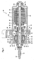
- the Actuator 10 has one at the free end Actuating shaft 12 has a pinion 14, via which a Not shown differential lock of a vehicle can be operated.
- the Actuator a drive unit 16 and electromagnetic brake unit 18, the Drive unit 16 and the brake unit 18 in one common housing 20 is housed.
- the housing 20 comprises a cup-shaped base housing 22, which the Drive unit 16 receives.
- the housing 20 further comprises a housing cover 24 in which the brake unit 18th is housed. By means of connecting screws 26 Housing cover 24 tightly screwed to the base housing 20 become.
- the drive unit 16 comprises permanent magnets on the housing side 28, the one on the actuating shaft 12 rotatably arranged anchor package 30 cooperate. Also includes the drive unit 16 one on the operating shaft non-rotatably arranged commutator 32 against which The outer surface of brushes 36 mounted in quivers 34 act.
- the Quiver 34 are in this case perpendicular to the longitudinal axis 38 the actuating shaft 12 arranged brush support plate 40 attached.
- On the brush support plate 40 are also various electrical components, for example suppressors, intended.
- the brake unit 18 includes a non-rotatable on the Actuating shaft 12 arranged brake hub flange 42 and one against the housing cover 24 secured against rotation, one Brake winding 44 comprising brake body 46. Also includes the brake unit 18 opposite the actuating shaft 12 rotatably arranged, axially movable brake disc 48, which is designed as a brake disc ring. at Energizing the brake winding 44 acts on the brake disc 48 against the likewise annular brake body 46. Consequently, when the brake winding 46 is energized, the Braking effect and the actuating shaft 12 is on the Brake hub flange 42, the brake disc 48 and the Brake body 46 against the housing 20 or against the Housing cover 24 secured against rotation.
- the brake body 46 in the housing cover 24 sees the Brake body 46 extending coaxially to the longitudinal axis 38 Pin 50 in front, which in appropriately trained, projecting blind holes 52 on the housing cover side.
- the brake body 46 within the housing cover 24 are caulking sections 54 on the housing cover 24 provided that in corresponding sections on the Shell surface of the brake body 46 are caulked.
- a spring element 58 provided that the brake disc 48 against the Brake disc support section 56 acted upon.
- notches 66 and 68 are provided along a line.
- the Notch 66 is in the area of the brake hub flange 42 and the notch 68 in the area of the drive unit 16.
- the actuating shaft 12 has a total of four notches 66 and four notches 68 each.
- the notches 66, 68 are each offset by 90 °.
- the notches as such, each have a notch angle of 90 °.
- the height h of the notches is in the range of about 2/100 mm.
- the Actuating shaft 12 no notches. These areas can be ground to achieve high accuracy his. After the grinding process, the notches 66, 68 in the actuating shaft are introduced.
- the notches have 66, 68 each have conical sections 70 at their endings, which extend in the axial direction over the length 1.
- the inside of the brake hub flange 42 has one on the actuating shaft 12 tapered section 72 on. Due to the conical sections 70 and conical section 72 takes place when joining the Brake hub flange 42 with the actuating shaft 12 a Self-centering. When joining the bumps dig Notches 66, 68 in the inside of the preferably from Aluminum trained brake hub flange 42 a. Between the brake hub flange 42 and the actuating shaft 12 consequently a notch press connection that with relative low press-in forces can be realized.
- the notches 68 act in the assembled state as in Figure 1 is shown with the anchor package 30 and with the Commutator 32 together. Because of the conical sections 70 the notches 68 also occur here when joining Self-centering. Because advantageously the form-fitting Firm fit between the actuating shaft 12 and the commutator 32 or the anchor package 30 only in the increases of Notches 68 occurs, the press-in forces can be relative be kept low.
- the ground section of the Actuating shaft 12, which in the installed state with the Bearing element 62 cooperates when joining the Actuating shaft 12 with commutator 32 and armature package 30 not affected.
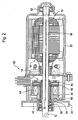
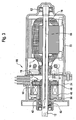
- FIG. 2 shows a second one according to the invention Actuating device 80 and a third in FIG Actuating device 90 according to the invention shown.
- the the actuating device 10 are corresponding components with the actuators 80 and 90 with the same Provide reference numbers.
- the actuator 80 differs from that Actuator 10 and others in that the brake unit-side bearing element 82 directly on the actuating shaft 12 arranged bearing section having. Furthermore, the brake body 46 is not arranged on the housing cover side, but is via a Plain bearing 84 arranged on the brake hub flange 42. to Anti-rotation of the brake body 46 is a according to Figure 2 in a toothing arranged on the housing cover side engaging nose 86 provided.
- the embodiment according to FIG. 2 has the advantage that the between the brake body 46 and the brake disc 48 Air gap to be provided in the brake body 46 and the Brake disc 48 having fixed assembly can be.
- FIG. 1 Another difference between the actuator 10 according to FIG. 1 and the actuating device 80 according to Figure 2 is that in the actuator 80 none two notches 66 and 68 arranged along a line are provided. Rather, they are about Drive unit 16 and the braking unit 18 extending Notches 88 are provided. The notches 88 'are corresponding Figures 4 and 5 formed. Because no Interruptions in the notches 88 are provided, these are easier to manufacture.
- the actuator 90 differs from the actuator 80 in that the brake disc carrier 56 separately from the Brake hub flange 42 is formed as a separate component.
- the brake disc carrier 56 is here a Brake disc hub 57 arranged on the actuating shaft 12.
- the Air gap between the brake disc 48 and the brake body 46 still during the assembly of the brake hub flange 42 or of the brake disc support portion 56 can be adjusted.
Landscapes
- Physics & Mathematics (AREA)
- Electromagnetism (AREA)
- Engineering & Computer Science (AREA)
- Power Engineering (AREA)
- Braking Arrangements (AREA)
- Retarders (AREA)
Applications Claiming Priority (2)
| Application Number | Priority Date | Filing Date | Title |
|---|---|---|---|
| DE10160847 | 2001-12-12 | ||
| DE10160847A DE10160847A1 (de) | 2001-12-12 | 2001-12-12 | Betätigungsvorrichtung, insbesondere zur Betätigung von Sperrdifferentialen von Fahrzeugen |
Publications (2)
| Publication Number | Publication Date |
|---|---|
| EP1320175A2 true EP1320175A2 (fr) | 2003-06-18 |
| EP1320175A3 EP1320175A3 (fr) | 2005-02-16 |
Family
ID=7708815
Family Applications (1)
| Application Number | Title | Priority Date | Filing Date |
|---|---|---|---|
| EP02027037A Withdrawn EP1320175A3 (fr) | 2001-12-12 | 2002-12-03 | Dispositif d'actionnement, notamment pour actionner le verouillage d'un différentiel dans des véhicules |
Country Status (3)
| Country | Link |
|---|---|
| US (1) | US6909213B2 (fr) |
| EP (1) | EP1320175A3 (fr) |
| DE (1) | DE10160847A1 (fr) |
Cited By (4)
| Publication number | Priority date | Publication date | Assignee | Title |
|---|---|---|---|---|
| WO2006058803A1 (fr) | 2004-12-01 | 2006-06-08 | Robert Bosch Gmbh | Dispositif de verrouillage, unite d'entrainement a engrenage comprenant un dispositif de verrouillage de ce type, et procede pour realiser une unite d'entrainement a engrenage de ce type |
| US7594566B2 (en) | 2005-11-29 | 2009-09-29 | Robert Bosch Gmbh | Lock device, transmission/drive unit containing such a lock device, and method for manufacturing such a transmission/drive unit |
| US7921977B2 (en) | 2005-11-29 | 2011-04-12 | Robert Bosch Gmbh | Lock device, transmission/drive unit containing such a lock device, and method for manufacturing such a transmission/drive unit |
| WO2020207576A1 (fr) * | 2019-04-10 | 2020-10-15 | Pierburg Pump Technology Gmbh | Unité auxiliaire automotrice dotée d'un moteur électrique |
Families Citing this family (11)
| Publication number | Priority date | Publication date | Assignee | Title |
|---|---|---|---|---|
| US7360122B2 (en) * | 2002-02-22 | 2008-04-15 | Bea Systems, Inc. | Method for initiating a sub-system health check |
| US7233989B2 (en) * | 2002-02-22 | 2007-06-19 | Bea Systems, Inc. | Method for automatic monitoring of managed server health |
| US7152185B2 (en) * | 2002-02-22 | 2006-12-19 | Bea Systems, Inc. | Method for event triggered monitoring of managed server health |
| WO2004076095A1 (fr) * | 2003-02-27 | 2004-09-10 | Mitsuba Corporation | Arbre et dispositif pour façonner un arbre |
| US20070137966A1 (en) * | 2004-02-27 | 2007-06-21 | Borgwarner Inc. | Electrohydraulic clutch assembly |
| DE202004012704U1 (de) * | 2004-08-12 | 2005-12-22 | Robert Bosch Gmbh | Ankerwelle für eine elektrische Maschine |
| US8235198B2 (en) * | 2008-11-20 | 2012-08-07 | Borgwarner, Inc. | Hydraulic clutch assembly for a motor vehicle driveline |
| US9114956B2 (en) * | 2010-06-18 | 2015-08-25 | Mitsubishi Electric Corporation | Elevator modification work apparatus |
| DE102010039008A1 (de) * | 2010-08-06 | 2012-02-09 | Hirschvogel Umformtechnik Gmbh | Rotor und Herstellungsverfahren hierzu |
| US20120177494A1 (en) * | 2011-01-06 | 2012-07-12 | General Electric Company | Steam turbine rotor with mechanically coupled high and low temperature sections using different materials |
| JP2014033549A (ja) * | 2012-08-03 | 2014-02-20 | Yaskawa Electric Corp | ロータ、回転電機及びロータの製造方法 |
Family Cites Families (18)
| Publication number | Priority date | Publication date | Assignee | Title |
|---|---|---|---|---|
| US2514693A (en) * | 1944-06-21 | 1950-07-11 | Garrett Corp | Motor assembly with magnetic brake |
| US2628321A (en) * | 1951-12-19 | 1953-02-10 | Jack & Heintz Inc | Electric motor brake-coupling assembly |
| US3068975A (en) * | 1958-11-08 | 1962-12-18 | Theuer Johann | Prime mover with automatic brake |
| DE1907289U (de) * | 1964-02-17 | 1964-12-23 | August Stickan | Kraftfahrzeugkupplungsscheibe mit genuteter nabe. |
| DE1913518U (de) * | 1964-12-16 | 1965-04-08 | Horst Fischer | Schalthebel-befestigungsvorrichtung auf hohlwellen, insbesondere fuer gabelstapler. |
| FR2126563A5 (fr) * | 1971-02-10 | 1972-10-06 | Samm | |
| DE2257290C3 (de) * | 1972-11-22 | 1978-09-28 | Siemens Ag, 1000 Berlin Und 8000 Muenchen | Elektromagnetische Bremse für Wechselstrommotoren |
| US4585967A (en) * | 1983-10-21 | 1986-04-29 | General Electric Company | Rotor of AC dynamoelectric machine with improved cooling and stability and method of making the same |
| DE3910888A1 (de) * | 1989-04-04 | 1990-10-11 | Mayr Christian Gmbh & Co Kg | Positionierantrieb |
| JPH0366561U (fr) * | 1989-10-30 | 1991-06-27 | ||
| FR2755313B1 (fr) * | 1996-02-15 | 1999-07-09 | Mitsuba Corp | Moteur a reducteur de vitesse |
| US5867892A (en) * | 1995-08-17 | 1999-02-09 | Globe Products Inc. | Method and apparatus for rotationally orienting an armature shaft |
| EP0902880B1 (fr) * | 1996-06-05 | 2002-10-23 | Valeo Auto-Electric Wischer und Motoren GmbH | Tore magnetique |
| JPH1075547A (ja) * | 1996-06-28 | 1998-03-17 | Mitsuba Corp | ピストンポンプおよびピストンポンプ駆動用の電動モータの組付け方法 |
| DE19702737A1 (de) * | 1997-01-27 | 1998-07-30 | Hilti Ag | Elektromotor |
| DE19946084A1 (de) * | 1999-09-25 | 2001-04-05 | Christoph Klesen | Elektromechanische Antriebseinheit |
| FI113505B (fi) * | 2000-01-17 | 2004-04-30 | Kci Kone Cranes Int Oy | Menetelmä ja sovitelma oikosulkumoottorin levyjarrun säätämiseksi |
| DE20014614U1 (de) * | 2000-08-23 | 2000-11-23 | MegaPlast GmbH & Co. KG, 78052 Villingen-Schwenningen | Elektrodenhalter |
-
2001
- 2001-12-12 DE DE10160847A patent/DE10160847A1/de not_active Ceased
-
2002
- 2002-12-03 EP EP02027037A patent/EP1320175A3/fr not_active Withdrawn
- 2002-12-12 US US10/318,994 patent/US6909213B2/en not_active Expired - Lifetime
Cited By (6)
| Publication number | Priority date | Publication date | Assignee | Title |
|---|---|---|---|---|
| WO2006058803A1 (fr) | 2004-12-01 | 2006-06-08 | Robert Bosch Gmbh | Dispositif de verrouillage, unite d'entrainement a engrenage comprenant un dispositif de verrouillage de ce type, et procede pour realiser une unite d'entrainement a engrenage de ce type |
| US8746421B2 (en) | 2004-12-01 | 2014-06-10 | Robert Bosch Gmbh | Blocking device, gear-drive unit containing such a blocking device, and method for producing such a gear-drive unit |
| US9906095B2 (en) | 2004-12-01 | 2018-02-27 | Robert Bosch Gmbh | Blocking device, gear-drive unit containing such a blocking device, and method for producing such a gear-drive unit |
| US7594566B2 (en) | 2005-11-29 | 2009-09-29 | Robert Bosch Gmbh | Lock device, transmission/drive unit containing such a lock device, and method for manufacturing such a transmission/drive unit |
| US7921977B2 (en) | 2005-11-29 | 2011-04-12 | Robert Bosch Gmbh | Lock device, transmission/drive unit containing such a lock device, and method for manufacturing such a transmission/drive unit |
| WO2020207576A1 (fr) * | 2019-04-10 | 2020-10-15 | Pierburg Pump Technology Gmbh | Unité auxiliaire automotrice dotée d'un moteur électrique |
Also Published As
| Publication number | Publication date |
|---|---|
| US20030136618A1 (en) | 2003-07-24 |
| US6909213B2 (en) | 2005-06-21 |
| DE10160847A1 (de) | 2003-07-17 |
| EP1320175A3 (fr) | 2005-02-16 |
Similar Documents
| Publication | Publication Date | Title |
|---|---|---|
| EP1320175A2 (fr) | Dispositif d'actionnement, notamment pour actionner le verouillage d'un différentiel dans des véhicules | |
| WO2019138068A1 (fr) | Système d'entraînement motorisé, utilisation du système d'entraînement pour l'actionnement d'une porte, procédé de fabrication pour un système d'entraînement | |
| EP1042854A1 (fr) | Petit moteur a collecteur | |
| DE10007262B4 (de) | Anordnung eines Elektromotors an der Kurbelwelle einer Brennkraftmaschine bei einem Kraftfahrzeug | |
| DE3243513A1 (de) | Antriebsanordnung fuer ein kraftfahrzeug | |
| DE102014218034A1 (de) | Positionierung eines umspritzten Stators für einen Kupplungsaktor oder einen Getriebeaktor und Einbringen eines Rotorlagemagneten in einen solchen Aktor | |
| EP1664470B1 (fr) | Systeme d'entrainement pour dispositifs de reglage de vehicules automobiles | |
| DE19652929A1 (de) | Antriebsvorrichtung für eine Scheibenwischanlage | |
| EP1797353B1 (fr) | Procede de fabrication d'une transmission et transmission ainsi fabriquee | |
| EP1011188B1 (fr) | Moteur électrique avec frein intégré actionné électromagnétiquement et sans jeu de rotation | |
| EP1320176B1 (fr) | Dispositif d'actionnement, notamment pour actionner le verouillage d'un différentiel dans des véhicules | |
| EP1526308B1 (fr) | Dispositif de palier, notamment pour une transmission | |
| DE102015206818A1 (de) | Elektrische Antriebseinheit, sowie ein Wankstabilisator beinhaltend eine solche Antriebseinheit und ein Herstellungsverfahren eines solchen Wankstabilisators | |
| EP1009089A2 (fr) | Actionneur électrique pour un véhicule automobile | |
| DE202023101624U1 (de) | Stellvorrichtung für ein Fahrzeug, Fahrzeug zum Betreiben einer Stellvorrichtung | |
| DE102007035748A1 (de) | Sperrvorrichtung sowie Getriebe-Antriebs-Einheit | |
| EP1667892B1 (fr) | Dispositif servant a superposer des mouvements de braquage pour un systeme d'assistance de direction et procede pour faire fonctionner ce dispositif | |
| EP1958315B1 (fr) | Dispositif de blocage, unité d entraînement à engrenage comprenant un tel dispositif de blocage et procédé pour fabriquer une telle unité d entraînement à engrenage | |
| WO1999027272A1 (fr) | Dispositif de freinage a actionnement electrique pour vehicules automobiles | |
| EP0805543A2 (fr) | Moteur électrique | |
| DE102024104087B4 (de) | Forcefeedback-Aktuator einer Lenksäule | |
| BE1031438B1 (de) | Lenksystem für ein Kraftfahrzeug | |
| EP1673549B1 (fr) | Frein a disque comportant un dispositif de rattrapage de jeu entraine par un moteur electrique | |
| DE102025109284A1 (de) | Aktorbaugruppe | |
| DE102024209607A1 (de) | Elektromotor-Getriebe-Baueinheit |
Legal Events
| Date | Code | Title | Description |
|---|---|---|---|
| PUAI | Public reference made under article 153(3) epc to a published international application that has entered the european phase |
Free format text: ORIGINAL CODE: 0009012 |
|
| 17P | Request for examination filed |
Effective date: 20021203 |
|
| AK | Designated contracting states |
Designated state(s): AT BE BG CH CY CZ DE DK EE ES FI FR GB GR IE IT LI LU MC NL PT SE SI SK TR |
|
| AX | Request for extension of the european patent |
Extension state: AL LT LV MK RO |
|
| PUAL | Search report despatched |
Free format text: ORIGINAL CODE: 0009013 |
|
| AK | Designated contracting states |
Kind code of ref document: A3 Designated state(s): AT BE BG CH CY CZ DE DK EE ES FI FR GB GR IE IT LI LU MC NL PT SE SI SK TR |
|
| AX | Request for extension of the european patent |
Extension state: AL LT LV MK RO |
|
| RIC1 | Information provided on ipc code assigned before grant |
Ipc: 7H 02K 7/102 A |
|
| AKX | Designation fees paid |
Designated state(s): DE ES FR GB IT |
|
| STAA | Information on the status of an ep patent application or granted ep patent |
Free format text: STATUS: THE APPLICATION IS DEEMED TO BE WITHDRAWN |
|
| 18D | Application deemed to be withdrawn |
Effective date: 20060620 |