EP1320896B1 - Corps en matériau semi-conducteur à longueur de libre parcours moyen réduit - Google Patents
Corps en matériau semi-conducteur à longueur de libre parcours moyen réduit Download PDFInfo
- Publication number
- EP1320896B1 EP1320896B1 EP01969730A EP01969730A EP1320896B1 EP 1320896 B1 EP1320896 B1 EP 1320896B1 EP 01969730 A EP01969730 A EP 01969730A EP 01969730 A EP01969730 A EP 01969730A EP 1320896 B1 EP1320896 B1 EP 1320896B1
- Authority
- EP
- European Patent Office
- Prior art keywords
- free path
- path length
- mean free
- semiconductor material
- region
- Prior art date
- Legal status (The legal status is an assumption and is not a legal conclusion. Google has not performed a legal analysis and makes no representation as to the accuracy of the status listed.)
- Expired - Lifetime
Links
Images

Classifications
-
- H—ELECTRICITY
- H10—SEMICONDUCTOR DEVICES; ELECTRIC SOLID-STATE DEVICES NOT OTHERWISE PROVIDED FOR
- H10D—INORGANIC ELECTRIC SEMICONDUCTOR DEVICES
- H10D30/00—Field-effect transistors [FET]
- H10D30/60—Insulated-gate field-effect transistors [IGFET]
- H10D30/64—Double-diffused metal-oxide semiconductor [DMOS] FETs
- H10D30/65—Lateral DMOS [LDMOS] FETs
- H10D30/657—Lateral DMOS [LDMOS] FETs having substrates comprising insulating layers, e.g. SOI-LDMOS transistors
-
- H—ELECTRICITY
- H10—SEMICONDUCTOR DEVICES; ELECTRIC SOLID-STATE DEVICES NOT OTHERWISE PROVIDED FOR
- H10D—INORGANIC ELECTRIC SEMICONDUCTOR DEVICES
- H10D62/00—Semiconductor bodies, or regions thereof, of devices having potential barriers
- H10D62/50—Physical imperfections
- H10D62/53—Physical imperfections the imperfections being within the semiconductor body
-
- H—ELECTRICITY
- H10—SEMICONDUCTOR DEVICES; ELECTRIC SOLID-STATE DEVICES NOT OTHERWISE PROVIDED FOR
- H10D—INORGANIC ELECTRIC SEMICONDUCTOR DEVICES
- H10D8/00—Diodes
Definitions
- the invention relates to a body of doped semiconductor material of at least one conductivity type, which has a mean free path for free charge carriers in the semiconductor material and at least one region in which an average free path for the free charge carriers in the semiconductor material is present, which is relative to a mean free path of the semiconductor material for the free charge carriers is reduced.
- German patent application 10030381.1 2000 P 12486
- the area of reduced mean free path for the free charge carriers in the semiconductor material generally leads to better electrical properties of the body of semiconductor material. This is the case with the already proposed body Through this range, a high electrical breakdown strength achieved.
- the EP 0 797 257 A shows a power thyristor, in the n-doped base implantation areas generated by implantation of heavy ions are regularly arranged.
- the implantation damages the crystal structure of the thyristor in the implantation regions and reduces the carrier lifetime compared to the unirradiated regions of the n-doped base.
- the object of the invention is to provide a body of the type mentioned, which has even better electrical properties.
- the area of reduced average free path length has sections which follow one another in at least one specific direction and between which there is at least one area in which a mean free path length for the free charge carriers in relation to the reduced mean free path length Semiconductor material prevails.
- the area of reduced mean free path is not interrupted as in the previously proposed body, but interrupted by at least one area with a relatively large mean free path relative to this path. This will cause the generation of Charge carriers are hindered by impact ionization in the region of reduced mean free path through the reduced free path of the charge carriers.
- the geometry of each region In the region or regions in which the average free path for the free charge carriers in the semiconductor material is greater relative to the reduced mean free path, this is achieved by the geometry of each region.
- the charge carriers need a certain path length in order to be able to absorb sufficient energy in order to be able to generate additional charge carriers by impact ionization. If this path length is kept small, these charge carriers can not absorb enough energy.
- an electric current flow is not exclusive takes place in a region of reduced mean free path, but that the flow also flows in at least one region where the mean free path is greater than the reduced mean free path.
- the body according to the invention advantageously realize a component with a body of semiconductor material in which the free path length of the charge carriers does not have to be reduced everywhere where a high electric field strength prevails.
- An advantageous embodiment of the body according to the invention is designed such that a distance between adjacent areas with relatively reduced mean free path greater average free path length, which are separated by a distance determining portion of the reduced average free path, so the amount of one by applying depends on a specific electrical voltage to the body in the semiconductor material generated electric field strength that this distance is smaller at a position of smaller amount and larger at a position greater amount.
- this may mean that such areas are arranged there in greater density, where the magnitude of the electric field strength is smaller, and are arranged there in a lower density, where the magnitude of the electric field strength is greater.
- Another advantageous embodiment of the body according to the invention is designed so that a distance between adjacent sections of the reduced average free path area, the area through an area with a relative to the reduced mean free path greater mean free Path length are separated, so depends on the amount of electric field strength generated by applying a certain electrical voltage to the body in the semiconductor material, that this distance is smaller at a position smaller amount and smaller at a position of greater magnitude.
- this may mean that such sections are arranged there in greater density, where the magnitude of the electric field strength is greater, and are arranged there in a lower density, where the magnitude of the electric field strength is smaller.
- the relatively larger mean free path of a region is equal to a mean free path of the doped semiconductor material of the one conductivity type outside of the region of reduced mean free path.
- a distance between adjacent regions, which are separated by a section of the region of reduced mean free path, in such a way depends on the amount of electric field strength generated by applying a certain electrical reverse voltage to the junction in the semiconductor material this distance is greater at a point of lesser amount and smaller at a point of greater magnitude.
- a high-voltage component can be realized with a body made of semiconductor material, on the one hand low on-and switching losses, on the other hand, but also has a small component volume.
- a high-voltage device with low volume and a high-voltage IC (HVIC) highest integration can be realized.
- High-voltage components are today essentially realized by the choice of the lowest possible basic doping in an n-doped base of his body made of semiconductor material. This measure is set from the point of view of the lowest possible total power loss in the device limits, since the reduction of the basic doping i.a. also an increased component thickness conditional.
- HVICs are u.a. realized in either "Junction Isolation” technique (JI technique) or "Dielectric Isolation” technique (DI technique). In both techniques, a "thick" drift zone is required to accommodate the necessary reverse voltage.
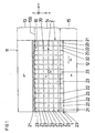
- the body of doped semiconductor material is generally designated 1 and the region of reduced mean free path is generally designated 2.
- the region 2 is in both cases, for example, substantially only in n-doped semiconductor material of the body 1, ie in semiconductor material of the conductivity type n. Essentially means that it makes sense in many cases, the region 2 in semiconductor material of the conductivity type p of Body 1, which has a high electric field strength to expand, for example, as in the FIGS. 1 and 2 is indicated.
- the region 2 of reduced average free path ⁇ r has sections which follow one another in at least one specific direction and between which there is at least one region in which there is a greater average free path for the free charge carriers in the semiconductor material relative to the reduced mean free path ⁇ r.
- Analogous can also be given in the direction perpendicular to the directions x and y and the plane of the figures z direction.
- each region 23 is completely enclosed by sections 21 and 22 of region 2, and moreover, specifically, the regions 23 in the directions x and y are arrayed as in rows and columns.
- Each section 21 extends in the direction y through the entire area 2
- each section 22 extends in the direction x through the entire area 2, and the sections 21 and 22 intersect and enclose the areas 23 therebetween.
- the semiconductor material For each conductivity type p or n, the semiconductor material has a given average free path ⁇ 0 for free charge carriers in the semiconductor material.
- the region 2 of the reduced mean free path ⁇ r extends essentially only in the n-doped semiconductor material and adjoins at least the pn junction 10 of the body 1.
- the direction x, in which the sections 21 follow one another and between which the regions 23 are present, is for example perpendicular to the surface 100 in which the pn junction 10 extends.
- direction z which is likewise aligned parallel to the surface 100 in which the pn junction 10 extends.
- the body 1 after FIG. 1 is that of a high-blocking diode.
- This body 1 whose semiconductor material consists for example of silicon, has, for example, a p + -doped region 13, which is adjacent to a surface section 11 of this body 1 and arranged on the surface section 11, not shown, of the diode, one on the surface section 11 A side of the region 13 adjacent to this region 13 n-doped region 14 and on the side facing away from the surface portion 11 of the portion 14 adjacent to this region 14 n + -doped region 15, which also faces away from the surface portion 11 surface portion 12th of the body 1 and is contacted by a disposed on the surface portion 12, not shown terminal electrode of the diode.
- the interface between the p + doped region 13 and the n-doped region 14 forms the surface 100 in which the pn junction 10 of the diode extends.
- the portion 21 and 22 and the areas 23 having reduced average free path length extends substantially only over the n-doped region 14, ie it generally projects only slightly into the p + -doped region 13 and / or in the n + doped area 15 into it.
- this extension and the other requirements of area 2 see the in the earlier German patent application 10030381.1 what has been said about it, which also applies here.
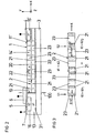
- the body 1 after FIG. 2 is that of a high-voltage MOS device.
- This body 1 which likewise consists, for example, of silicon, is arranged, for example, on the surface 31 of a substrate 3 made of electrically insulating material, for example SiO 2 .
- the pn junction 10 of this body 1 extends in the surface 100 perpendicular to the surface 31 of the substrate 3 and separates a left p + doped region 13 'of the body 1 from a right n-doped region 14' of the body 1.
- Both the p + -doped region 13 'as well as the n-doped region 14' each adjoin a surface portion 11 'of the body 1 facing away from the substrate 3.
- an n + -doped region 15' is arranged, which adjoins the surface portion 11 'of the body 1 and from a disposed on the surface portion 11' drain electrode 4 of Component is contacted.
- an n + -doped region 16 is arranged at a distance from the pn junction 10, which region adjoins the surface section 11' of the body 1.
- a layer 5 of electrically insulating material is arranged on the surface section 11 'of the body 1, extending from the n-doped region 14' via the p + -doped region 13 'into the n + -doped region 16 extends and covers only a portion of the area 13 'and the area 16.
- a gate electrode 6 of the component is arranged above the pn junction 10, which likewise extends from the n-doped region 14 'via the p + -doped region 13' into the n + -doped region 16 extends.
- the uncovered part of the region 13 'and of the region 16 are contacted in common by a source electrode 7 of the component arranged on the surface portion 11' of the body 1.
- the interface between the p + doped region 13 and the n-doped region 14 forms the surface 100 in which the pn junction 10 of the diode extends.
- the regions 21 and 22 of reduced average free path ⁇ r and the regions 23 having region 2 of reduced mean free path ⁇ r having relatively smaller mean free path ⁇ r of larger mean free path extend essentially only over n-doped region 14 ', ie it projects, ia, only slightly into the p + -doped region 13 'and / or into the n + -doped region 15'.
- this extension and the other requirements of the area 2 see also here in the older German patent application 10030381.1 what has been said about it, which also applies here.
- FIG. 3 shows a section of a region 2 reduced average free path length of a body 1 according to the invention in the sectional view of the FIGS. 1 and 2 ,
- sections 21 of the region 2 in each case the reduced mean free path ⁇ r, follow each other in the direction x, and between these sections 21 there are regions 23, in each of which a larger relative to the reduced mean free path ⁇ r mean free path for the free charge carriers in the n-doped semiconductor material, for example, the given greater path length ⁇ 0, prevails.
- this region 2 is a distance between adjacent regions 23 relative to the reduced mean free path ⁇ r of larger mean free path, which are separated by a section 21 of region 2 of reduced mean free path ⁇ r and which section 21 this distance by its extension d in of the direction x, thus of the magnitude
- the distance d at the left-hand position S1 has a value d1 which is smaller than the value d2 of the distance d at the right-hand position S2.
- this may mean that such regions 23 are arranged there in greater density, where the magnitude
- each region 23 in the direction x may be the same or different for several or all regions 23.
- FIG. 4 shows a section of a region 2 reduced mean free path of a body 1 in the sectional view of the FIGS. 1 and 2 ,
- sections 21 of the region 2 in each of which the reduced mean free path ⁇ r prevails also follow each other in the direction x, and between these sections 21 there are regions 23, in each of which a relative to the reduced mean free path ⁇ r larger mean free path for the free charge carriers in the n-doped semiconductor material, for example the given longer path length ⁇ 0, prevails.
- FIG. 4 is a distance between adjacent portions 21 of the region 2 of reduced average free path ⁇ r separated by a region 23 having a mean free path relative to the reduced mean free path ⁇ r, and which region 23 this distance by its extension b in the direction x determined, so from the amount
- the distance b at the left-hand position S1 has a value b1 that is greater than the value b2 of the distance b at the right-hand position S2.
- this may mean that such sections 21 are arranged there in greater density, where the amount
- each section 21 in the direction x may be the same or different for a plurality or all sections 21.
Landscapes
- Electrodes Of Semiconductors (AREA)
- Thin Film Transistor (AREA)
Claims (6)
- Corps (1) en matériau semi-conducteur dopé d'au moins un type (n ; p) de conductivité, qui a une longueur (λ0) de libre parcours moyen pour des porteurs de charge libres dans le matériau semi-conducteur et au moins une zone (2) dans laquelle une longueur (λr) de libre parcours moyen des porteurs de charge libres est présente dans le matériau semi-conducteur, qui est réduite par rapport à une longueur (λ0) de libre parcours moyen du matériau semi-conducteur pour les porteurs de charge libres,- dans lequel la zone (2) de longueur (λr) de libre parcours moyen réduite a des parties (21, 22) qui se succèdent dans au moins une direction (x, y, z) déterminée et il y a entre elles au moins une région (23) dans laquelle règne une longueur (λ0) de libre parcours moyen plus grande que la longueur (λr) de libre parcours moyen réduite, caractérisé en ce qu'une distance (d) entre des régions (23) voisines ayant une longueur (λ0) de libre parcours moyen plus grande que la longueur (λr) de libre parcours moyen réduite, qui sont séparées par une partie (21) déterminant cette distance (d) de la zone (2) de longueur (λr) de libre parcours moyen réduite, dépend de la valeur absolue (|E|) d'une intensité (E) de champ électrique produite par application d'une tension électrique à des électrodes de borne du corps (1) dans le matériau semi-conducteur, de sorte que cette distance (d) est plus petite en un point de valeur absolue (|E|) plus petite et plus grande en un point de valeur absolue (|E|) plus grande.
- Corps suivant la revendication 1, dans lequel une distance (b) entre des parties (21) voisines de la zone (2) de longueur (λr) de libre parcours moyen réduite, qui sont séparées par une région (23) déterminant cette distance (b) et ayant une longueur (λ0) de libre parcours moyen plus grande que la longueur (λr) de libre parcours moyen réduite, dépend de la valeur absolue (|E|) d'une intensité (E) de champ électrique produite par application d'une tension électrique aux électrodes de borne du corps, de façon que cette distance (b) soit plus grande en un point de valeur absolue (|E|) plus petite et plus petite en un point de valeur absolue (|E|) plus grande.
- Corps (1) suivant l'une des revendications précédentes, dans lequel la longueur (λ0) de libre parcours moyen relativement plus grande d'une région (23) est égale à la longueur (λ0) de libre parcours moyen du matériau semi-conducteur d'un type (n ; p) de conductivité à l'extérieur de la zone (2) de longueur (λr) de libre parcours moyen réduite.
- Corps (1) suivant l'une des revendications précédentes, dans lequel le matériau semi-conducteur dopé est dopé de manière différente et- a au moins une jonction (10) entre un type (p ; n) de conductivité et un type (n ; p) de conductivité opposé à ce type (p ; n) de conductivité,- a, pour chaque type (n ; p) de conductivité, respectivement une longueur (λ0) de libre parcours moyen des porteurs de charge libres dans le matériau conducteur et- a, pour au moins l'un des deux types (n ; p) de conductivité, une zone (2) dans laquelle il y a une longueur (λr) de libre parcours moyen pour les porteurs de charge libres dans le matériau semi-conducteur, qui est réduite par rapport à la longueur (λ0) de libre parcours moyen des porteurs de charge libres du matériau semi-conducteur de type (n ; p) de conductivité,- dans lequel la zone (2) de longueur (λr) de libre parcours moyen réduite a des parties (21) qui se succèdent dans la direction (x) perpendiculairement à une surface dans laquelle s'étend la jonction (10) et entre lesquelles il y a au moins une région (23) dans laquelle une longueur (λ0) de libre parcours moyen des porteurs de charge libres est plus grande que la longueur (λr) de libre parcours moyen réduite, et/ou- dans lequel la zone (2) de longueur (λr) de libre parcours moyen réduite a des parties (22) qui se succèdent dans au moins une direction (y, z) parallèlement à la surface (100) dans laquelle s'étend la jonction (10) et entre lesquelles il y a au moins une région (23) dans laquelle règne une longueur (λ0) de libre parcours moyen des porteurs de charge plus grande que la longueur (λr) de libre parcours moyen réduite.
- Corps (1) suivant la revendication 4, dans lequel un distance (d) entre des régions (23) voisines ayant des longueurs (λ0) de libre parcours moyen plus grandes que la longueur (λr) de libre parcours moyen réduite, qui sont séparées par une partie (21), définissant cette distance (d), de la zone (2) de longueur (λr) de libre parcours moyen réduite, dépend de la valeur absolue (|E|) d'une intensité (E) de champ électrique produite par application d'une tension électrique de blocage à la jonction (10) dans le matériau semi-conducteur, de sorte que cette distance (d) est plus petite en un point de valeur absolue (|E|) plus petite et est plus grande en un point de valeur absolue (|E|) plus grande.
- Corps (1) suivant la revendication 4 ou 5, dans lequel une distance (b) entre des parties (21) voisines de la zone (2) de longueur (λr) de libre parcours moyen réduite, qui sont séparées par une région (23) définissant cette distance (b) et ayant une longueur (λ0) de libre parcours moyen plus grande que la longueur (λr) de libre parcours moyen réduite, dépend de la valeur absolue (|E|) d'une intensité (E) de champ électrique produite par application d'une tension de blocage électrique à la jonction (10) dans le matériau semi-conducteur, de sorte que cette distance (b) est plus grande en un point de valeur absolue (|E|) plus petite et plus petite en un point de valeur absolue (|E|) plus grande.
Applications Claiming Priority (3)
| Application Number | Priority Date | Filing Date | Title |
|---|---|---|---|
| DE10048345 | 2000-09-29 | ||
| DE10048345A DE10048345A1 (de) | 2000-09-29 | 2000-09-29 | Körper aus Halbleitermaterial mit reduzierter mittlerer freier Weglänge |
| PCT/EP2001/010751 WO2002027801A1 (fr) | 2000-09-29 | 2001-09-17 | Corps en materiau semi-conducteur a longueur de parcours libre moyenne reduite |
Publications (2)
| Publication Number | Publication Date |
|---|---|
| EP1320896A1 EP1320896A1 (fr) | 2003-06-25 |
| EP1320896B1 true EP1320896B1 (fr) | 2008-12-17 |
Family
ID=7658135
Family Applications (1)
| Application Number | Title | Priority Date | Filing Date |
|---|---|---|---|
| EP01969730A Expired - Lifetime EP1320896B1 (fr) | 2000-09-29 | 2001-09-17 | Corps en matériau semi-conducteur à longueur de libre parcours moyen réduit |
Country Status (5)
| Country | Link |
|---|---|
| US (1) | US6815793B2 (fr) |
| EP (1) | EP1320896B1 (fr) |
| JP (1) | JP4725877B2 (fr) |
| DE (2) | DE10048345A1 (fr) |
| WO (1) | WO2002027801A1 (fr) |
Family Cites Families (18)
| Publication number | Priority date | Publication date | Assignee | Title |
|---|---|---|---|---|
| JPS5174586A (en) * | 1974-12-24 | 1976-06-28 | Mitsubishi Electric Corp | Handotaisochi oyobi sonoseizoho |
| US4259683A (en) * | 1977-02-07 | 1981-03-31 | General Electric Company | High switching speed P-N junction devices with recombination means centrally located in high resistivity layer |
| JPS55111365U (fr) * | 1979-01-29 | 1980-08-05 | ||
| JPS62235782A (ja) * | 1986-04-07 | 1987-10-15 | Toyota Central Res & Dev Lab Inc | 半導体装置 |
| JPS649658A (en) * | 1987-07-01 | 1989-01-12 | Mitsubishi Electric Corp | Gto thyristor |
| FR2638892B1 (fr) * | 1988-11-09 | 1992-12-24 | Sgs Thomson Microelectronics | Procede de modulation de la quantite d'or diffusee dans un substrat de silicium et diode rapide obtenue par ce procede |
| DE59003052D1 (de) * | 1989-05-18 | 1993-11-18 | Asea Brown Boveri | Halbleiterbauelement. |
| JPH0650738B2 (ja) * | 1990-01-11 | 1994-06-29 | 株式会社東芝 | 半導体装置及びその製造方法 |
| DE4223914C2 (de) * | 1992-06-30 | 1996-01-25 | Fraunhofer Ges Forschung | Verfahren zum Herstellen eines vertikalen Leistungsbauelementes mit reduzierter Minoritätsträgerlebensdauer in dessen Driftstrecke |
| EP0622834A3 (fr) * | 1993-04-30 | 1998-02-11 | International Business Machines Corporation | Méthode pour prévenir le latch-up et améliorer la tension de claquage dans les MOSFET SOI |
| JPH08125200A (ja) * | 1994-10-25 | 1996-05-17 | Mitsubishi Electric Corp | 半導体装置及びその製造方法 |
| JPH0927592A (ja) * | 1995-07-10 | 1997-01-28 | Hitachi Ltd | 複合型半導体装置及びそれを用いた電力変換装置 |
| JP3394383B2 (ja) * | 1996-03-18 | 2003-04-07 | 三菱電機株式会社 | サイリスタの製造方法およびサイリスタ |
| JP3488599B2 (ja) * | 1996-10-17 | 2004-01-19 | 株式会社東芝 | 半導体装置 |
| GB9709642D0 (en) * | 1997-05-14 | 1997-07-02 | Plessey Semiconductors Ltd | Improvements in or relating to semiconductor devices |
| DE19730759C1 (de) * | 1997-07-17 | 1998-09-03 | Siemens Ag | Vertikaler Leistungs-MOSFET |
| WO1999009600A1 (fr) * | 1997-08-14 | 1999-02-25 | Mitsubishi Denki Kabushiki Kaisha | Dispositif a semiconducteur et procede de fabrication d'un tel dispositif |
| DE10030381B4 (de) | 2000-06-21 | 2005-04-14 | eupec Europäische Gesellschaft für Leistungshalbleiter mbH & Co. KG | Leistungshalbleiterbauelement aufweisend einen Körper aus Halbleitermaterial mit Übergang zwischen zueinander entgegengesetzten Leiterfähigkeitstypen |
-
2000
- 2000-09-29 DE DE10048345A patent/DE10048345A1/de not_active Ceased
-
2001
- 2001-09-17 EP EP01969730A patent/EP1320896B1/fr not_active Expired - Lifetime
- 2001-09-17 DE DE50114587T patent/DE50114587D1/de not_active Expired - Lifetime
- 2001-09-17 WO PCT/EP2001/010751 patent/WO2002027801A1/fr not_active Ceased
- 2001-09-17 JP JP2002531497A patent/JP4725877B2/ja not_active Expired - Lifetime
-
2003
- 2003-02-28 US US10/377,071 patent/US6815793B2/en not_active Expired - Lifetime
Also Published As
| Publication number | Publication date |
|---|---|
| WO2002027801A1 (fr) | 2002-04-04 |
| JP2004510353A (ja) | 2004-04-02 |
| US6815793B2 (en) | 2004-11-09 |
| DE10048345A1 (de) | 2002-05-16 |
| JP4725877B2 (ja) | 2011-07-13 |
| EP1320896A1 (fr) | 2003-06-25 |
| DE50114587D1 (de) | 2009-01-29 |
| US20030137027A1 (en) | 2003-07-24 |
Similar Documents
| Publication | Publication Date | Title |
|---|---|---|
| DE19811297B4 (de) | MOS-Halbleitervorrichtung mit hoher Durchbruchspannung | |
| DE19848828C2 (de) | Halbleiterbauelement mit kleiner Durchlaßspannung und hoher Sperrfähigkeit | |
| DE10153739B4 (de) | Halbleiterbauelement | |
| DE10041344B4 (de) | SJ-Halbleitervorrichtung | |
| DE69325608T2 (de) | Halbleiterbauelement mit einem Schutzmittel | |
| EP1142025B1 (fr) | Composant semi-conducteur de puissance | |
| EP1175700B1 (fr) | Composant a semi-conducteur | |
| DE19830332C2 (de) | Vertikales Halbleiterbauelement mit reduziertem elektrischem Oberflächenfeld | |
| EP0057256A2 (fr) | Transistor MIS vertical à effet de champ à résistance minime à l'état passant | |
| WO2000033385A1 (fr) | Transistor mos a effet de champ avec electrode auxiliaire | |
| DE3537004A1 (de) | Vdmos-baustein | |
| EP0888639A1 (fr) | Composant a semi-conducteur commande par effet de champ | |
| DE69302244T2 (de) | Halbleiter-Schutzkomponente | |
| DE102020116653A1 (de) | Siliziumcarbid-halbleiterbauelement | |
| DE19816448C1 (de) | Universal-Halbleiterscheibe für Hochspannungs-Halbleiterbauelemente, ihr Herstellungsverfahren und ihre Verwendung | |
| EP0913000A1 (fr) | Composant a semiconducteur pouvant etre commande par effet de champ | |
| DE10245049A1 (de) | Kompensationshalbleiterbauelement | |
| EP1116276B1 (fr) | Composant semi-conducteur comportant des regions de mise en forme de champ | |
| DE102004002723A1 (de) | Halbleiterbauelement mit einem SOI-Aufbau | |
| EP1245050B1 (fr) | Element de commutation a semi-conducteur commandable a blocage bidirectionnel | |
| EP1097482A1 (fr) | Ensemble a semi-conducteur, en particulier transistor a effet de champ a jonction | |
| DE10252609B4 (de) | Abschluß für ein Halbleiterbauteil mit MOS-Gatesteuerung mit Schutzringen | |
| EP0709899A2 (fr) | Diode semi-conductrice avec injecteur d'électrons | |
| DE3924930C2 (de) | MOS Halbleitervorrichtung | |
| EP0966761B1 (fr) | Transistor vertical bipolaire a grille isolee pourvu d'une structure du type silicium sur isolant |
Legal Events
| Date | Code | Title | Description |
|---|---|---|---|
| PUAI | Public reference made under article 153(3) epc to a published international application that has entered the european phase |
Free format text: ORIGINAL CODE: 0009012 |
|
| 17P | Request for examination filed |
Effective date: 20021206 |
|
| AK | Designated contracting states |
Designated state(s): AT BE CH CY DE DK ES FI FR GB GR IE IT LI LU MC NL PT SE TR |
|
| RBV | Designated contracting states (corrected) |
Designated state(s): AT BE CH DE FR GB LI |
|
| 17Q | First examination report despatched |
Effective date: 20050506 |
|
| RAP1 | Party data changed (applicant data changed or rights of an application transferred) |
Owner name: INFINEON TECHNOLOGIES AG |
|
| GRAP | Despatch of communication of intention to grant a patent |
Free format text: ORIGINAL CODE: EPIDOSNIGR1 |
|
| RBV | Designated contracting states (corrected) |
Designated state(s): DE FR GB |
|
| GRAS | Grant fee paid |
Free format text: ORIGINAL CODE: EPIDOSNIGR3 |
|
| GRAA | (expected) grant |
Free format text: ORIGINAL CODE: 0009210 |
|
| AK | Designated contracting states |
Kind code of ref document: B1 Designated state(s): DE FR GB |
|
| REG | Reference to a national code |
Ref country code: GB Ref legal event code: FG4D Free format text: NOT ENGLISH |
|
| REF | Corresponds to: |
Ref document number: 50114587 Country of ref document: DE Date of ref document: 20090129 Kind code of ref document: P |
|
| PLBE | No opposition filed within time limit |
Free format text: ORIGINAL CODE: 0009261 |
|
| STAA | Information on the status of an ep patent application or granted ep patent |
Free format text: STATUS: NO OPPOSITION FILED WITHIN TIME LIMIT |
|
| 26N | No opposition filed |
Effective date: 20090918 |
|
| GBPC | Gb: european patent ceased through non-payment of renewal fee |
Effective date: 20090917 |
|
| REG | Reference to a national code |
Ref country code: FR Ref legal event code: ST Effective date: 20100531 |
|
| PG25 | Lapsed in a contracting state [announced via postgrant information from national office to epo] |
Ref country code: FR Free format text: LAPSE BECAUSE OF NON-PAYMENT OF DUE FEES Effective date: 20090930 |
|
| PG25 | Lapsed in a contracting state [announced via postgrant information from national office to epo] |
Ref country code: GB Free format text: LAPSE BECAUSE OF NON-PAYMENT OF DUE FEES Effective date: 20090917 |
|
| PGFP | Annual fee paid to national office [announced via postgrant information from national office to epo] |
Ref country code: DE Payment date: 20181121 Year of fee payment: 18 |
|
| REG | Reference to a national code |
Ref country code: DE Ref legal event code: R119 Ref document number: 50114587 Country of ref document: DE |
|
| PG25 | Lapsed in a contracting state [announced via postgrant information from national office to epo] |
Ref country code: DE Free format text: LAPSE BECAUSE OF NON-PAYMENT OF DUE FEES Effective date: 20200401 |